 Aiming Song
 Hongtao Xu2*
94% of researchers rate our articles as excellent or good
Learn more about the work of our research integrity team to safeguard the quality of each article we publish.
Find out more
ORIGINAL RESEARCH article
Front. Mater., 07 April 2022
Sec. Structural Materials
Volume 9 - 2022 | https://doi.org/10.3389/fmats.2022.859687
This article is part of the Research TopicAdvanced Concretes and Their Structural ApplicationsView all 23 articles
A modified formula for average crack spacing and a numerical model for crack width in hogging moment regions of steel–concrete composite beams under fatigue loading are proposed in this article. First, the existing calculation formulas and test data of average crack spacing are discussed and summarized. By introducing the factor of transverse reinforcement spacing, a modified formula of crack spacing is suggested based on the method of non-linear fitting. Then, a numerical model for crack width in negative moment regions under fatigue loading is proposed. In the analytical model, the explicit formulations of slip occurring at both the beam–slab interface and the reinforcement–concrete interface are included by considering fatigue effects, as well as the stress of reinforcement in the cracked section. Finally, a fatigue test on two steel–concrete composite plate beams subjected to hogging moment is designed and conducted. Compared with the crack width evaluation methods in the existing literature, the analysis results of the numerical model show more reasonable agreement with the data of the experimental beams performed in this study.
A steel–concrete composite beam is a new type of structure developed on the basis of steel structures and reinforced concrete structures. It has been widely accepted by the engineering field, such as buildings and bridges (Liu et al., 2016; Wang et al., 2021). The steel beam and concrete slab are combined as a whole by welding shear connectors to achieve the purpose of synergistic work. Through reasonable section design, steel–concrete composite beams can give full play to the advantages of tensile strength of steel and the compressive strength of concrete. However, in the negative moment regions near the intermediate support of steel–concrete continuous composite beams, a complex non-linear behavior under the action of a low static load is due to the existence of adverse factors such as concrete tension and steel beam compression (Chen et al., 2009; Sun et al., 2014). In addition, under the long-term action of fatigue loads such as moving vehicles and wind strength, the service performance and durability of the structure are often further weakened (Wang et al., 2018). Among these shortcomings, cracking of the concrete slab has been one of the most crucial issues in hogging moment regions in composite girder bridges. For the design of a steel–concrete composite bridge, it is an economical and convenient solution to allow for the formation of cracks within the limit of acceptable widths (Ryu et al., 2004; Ryu et al., 2007). Moreover, the introduction of high-performance materials such as engineered cementitious composites (ECCs) (Qin et al., 2020; Zhang et al., 2021; Zhang et al., 2022) and ultra-high performance concrete (UHPC) (Luo et al., 2020) also provides an effective method for crack control.
There have been considerable experimental and theoretical studies on the concrete cracking and crack control of composite beams subjected to negative moments in the past. Ryu et al. (2007) studied the crack development and crack control measures in negative bending moment regions through fatigue loading tests of a full-size model of a two-span continuous composite beam manufactured with a prefabricated concrete slab. The structural strength and stiffness under fatigue loading still presented a good performance for the composite section, and the crack width of the prefabricated slab can be effectively controlled within the allowable range. El-Shihy et al. (2010) and El-Zohairy et al. (2017) conducted experimental tests and finite element analysis on composite beams under negative moments bonded with CFRP laminates. The results showed that CFRP laminates can effectively improve the cracking performance and bearing capacity in negative bending moment regions. Su et al. (2012) conducted an experimental study on the inelastic behavior in negative moment regions of steel–concrete composite box girders manufactured with inclined webs. The results showed that the longitudinal reinforcement ratio has an important influence on the crack propagation of concrete slabs, and the higher the reinforcement ratio, the better the effect of crack control. Fan et al. (2020) conducted static loading tests on steel and ECC beams under negative moment by taking the reinforcement ratio as the characteristic parameter. The results showed that ECC could significantly improve the stiffness and crack resistance of composite beams in the negative moment regions. Based on the four-parameter fiber bridge model, the tensile hardening equation of reinforced ECC members was deduced, and the crack width in negative moment regions of steel–ECC beams was calculated and analyzed. Song et al. (2021) developed a numerical calculation model of the crack width of steel–concrete composite beams under static negative moment regions by taking the bond–slip relationship at the reinforcement–concrete interface and the slip effect at the beam–slab interface into consideration. In addition, it was reported that the development of cracks is decisively influenced by transverse reinforcement (Ryu et al., 2005; He et al., 2010). To determine the minimum reinforcement with reference to the service load and to calculate the crack width, the transverse reinforcement must be taken into account (Ramm and Elz, 2002).
Till now, there are still no standard and applicable analytical methods for crack spacing and crack width in the negative moment regions of steel–concrete composite beams in the present design codes. In Eurocode 4-2 (2005), a simple way is suggested that crack width under negative moment could be calculated according to Eurocode 2 (2004). In China Code GB 50917-2013 (2013), the calculation formula for crack width in China Code GB 50010-2010 (2010) is employed to check the crack width of continuous composite beams. Moreover, very limited reports have studied the development laws of crack spacing and crack width in negative moment regions. Nie and Zhang (1997) conducted an experimental study on four simply supported composite steel–concrete beams under negative moments and two continuous two-span composite beams under point loads. Based on the experimental results and analysis, the formulas were proposed for estimating crack spacing and maximum crack width, which have been applied to the design practice of engineering. Yu and Guo (2004) conducted an experiment of eighteen partially prestressed steel-concrete composite beams subjected to negative moment. In terms of the test results, the formulas for calculating crack width in the negative bending region were presented, which coincided well with the current code for the design of concrete structures.
However, it is found that the models of present codes proposed to calculate the crack width of composite beams were employed from axial tension members, while the combination effect of steel beam on concrete slab was not fully considered. Like the analytical models presented in some existing literature, the fitted data from the tests conducted previously was limited and the slip at the beam–slab interface was not included. As a result, the existing models may attain unreasonable crack widths in the negative moment regions. For these reasons, it is very important to have a reliable analysis method for crack width that takes into account the effective behavior of steel–concrete composite beams under hogging moment. As a detailed and accurate method in the last decades, the finite element model based on suitable numerical procedures was utilized for the analysis of non-linear mechanical behavior and the calculation of crack width of reinforced concrete beams (Manfredi and Pecce, 1998; Fabbrocino et al., 2007; Oliveira et al., 2008; Castel et al., 2012), as well as the overall flexural behavior of composite beams under hogging moment (Manfredi et al., 1999). However, few researchers have conducted numerical research on crack width in the negative moment regions of continuous composite beams. In addition, most of the analytical methods were presented statically, while fatigue effects were rarely considered.
Set against the above background, this study aims to investigate the analytical methods of crack spacing and crack width in the hogging moment regions of steel–concrete composite beams under fatigue loading. A modified formula for crack spacing is suggested based on the existing equations by introducing the factor of transverse reinforcement spacing. The parameter associated with transverse reinforcement spacing is achieved by fitting the data from this study and some literature data. Owing to the fact that the current studies have not yet included an accurate method to evaluate the crack width in the negative moment regions of continuous composite beams considering fatigue effect, a numerical model is then proposed that includes explicit formulations of slip occurring at both the beam–slab interface and the reinforcement–concrete interface. Finally, a fatigue test on a steel–concrete composite plate beam subjected to hogging moment was conducted. Through comparing with the measured values of experimental work and the crack width evaluation methods in existing literature, the analysis results of the numerical model were verified.
Crack spacing directly affects the crack width of concrete. When the fatigue upper limit of the test beam is set at the crack development stage, new cracks will occur after a certain number of repeated cycles. And with the increase in loading times, the number of cracks tends to be stable. However, fatigue loading has little influence on the final crack spacing in the negative moment regions of composite beams when compared with static loading, which is similar to the development law obtained in reinforced concrete structures (Song, 2006). Therefore, the calculation method of the average crack spacing given in this section can be applied to the composite beams with studs both under fatigue loading and static loading, which can provide a basis for the establishment of the analytical method of crack width in the negative moment regions in the following section.
At present, several formulas have been proposed to predict the average crack spacing in the negative moment regions of continuous composite beams. However, the views on the influence factors of the existing formulas are not yet unified. The models employed by the design codes to calculate the average crack spacing were based on reinforced concrete structures, while the factors associated with composite beams were not fully taken into account. The common models in CEB-FIP (1978), China Code GBJ 10-89 (1989) and China Code GB 50010-2010 (2010) can be expressed, respectively, as follows:
An improved model based on China Code GBJ 10-89 (1989) was proposed by Wu et al. (1993), while the transverse reinforcement ratio and diameter were considered. The equation obtained was then as follows:
As the aforementioned models for average crack spacing showed no relation with the combination effect, the previous studies took the combined force ratio and spacing of stud connectors into consideration (Nie and Zhang, 1997; Yu and Guo, 2004), and two novel models were then proposed according to China Code GBJ 10-89 (1989) and China Code GB 50010-2010 (2010). The two equations are shown, respectively, as follows:
The development of cracking in slabs as part of composite beams is decisively influenced by the transverse reinforcement (Ramm and Elz, 2002). But this influence factor was not considered in the models mentioned earlier. A simple model which took the combined force ratio and transverse reinforcement spacing into account was established then by Zhang et al. (2011), while other important factors were not taken into account. The equation is given as follows:
In the aforementioned equations, lcr is the average crack spacing; k1 is the bonding performance coefficient of longitudinal tensile bars, and k1 = 0.4 is for a deformed bar; k2 is the influence coefficient of component stress distribution, and k2 = 0.25 is for a tension member; ν is the surface characteristics coefficient of longitudinal tensile bars, and ν = 0.7 is for deformed bar; cs is the concrete cover thickness of reinforcement; ls and la are the spacings of longitudinal reinforcement and transverse reinforcement, respectively; deq and dHeq are the equivalent diameters of longitudinal tensile bars and transverse bars, respectively; ρeq and ρHeq are the tensile reinforcement ratio and transverse reinforcement ratio, respectively; Rp is the combined force ratio; and p is the spacing of stud connectors.
In summary, the average crack spacing in the negative moment regions of continuous composite beams is mainly related to the concrete cover thickness of reinforcement, equivalent diameters of longitudinal tensile bars, the tensile reinforcement ratio, the combined force ratio, the spacing of stud connectors, and transverse reinforcement. However, the influence factors considered in the existing formulas mentioned before, proposed by researchers and codes, were not comprehensive.
In this section, a total of 38 specimen tests from previous literature were summarized and analyzed to study the influence factors of average crack spacing, as can be seen in Table 1. According to Eq. 6, which was based on China Code GB 50010-2010 (2010), a modified formula of crack spacing was proposed by introducing the factor of transverse reinforcement spacing la and taking the consistency of dimension into consideration. The parameters were achieved by fitting the data listed in Table 1 with the procedure shown in Figure 1. In this way, the novel model obtained was then as follows:
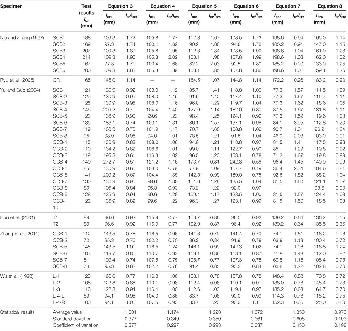
TABLE 1. Analysis of experimental test data obtained from the existing literature.
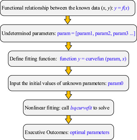
FIGURE 1. Flowchart of the fitting procedure.
The physical meaning of Eq. 8 is consistent with Eqs. 1–7 which were empirical formulas derived from data fitting. To verify the validity of the modified model described before, existing experiments conducted by Song et al. (2021) and He et al. (2010) were selected and analyzed with other proposed models expressed in Eqs 3–7. As is shown in Table 2, the maximum error was controlled within 10% for Eq. 8. Generally, it can be seen that the results of the modified formula are in better agreement with the experimental results compared with existing models. Hence, it is effective to use the modified model to study the average crack spacing in the negative moment regions of continuous composite beams.
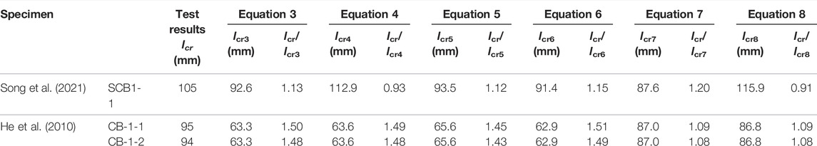
TABLE 2. Comparison of experimental and modeling results.
Crack opening of reinforced concrete beams under fatigue loading depends on several factors, most of which can be related to bond quality and to the effective area where reinforcement–concrete bond interaction may develop (Fabbrocino et al., 2007). As for composite beams, shear force at the beam–slab interface should also be included as an important factor in the analysis of the cracked section (Manfredi et al., 1999). In order to model these behaviors, it is necessary to give suitable constitutive laws of materials and an analytical model for crack width prediction.
When the fatigue upper limit is reached under normal service conditions, cracks in the concrete slab of composite beams under hogging moment will develop into the stabilized stage after a certain number of repeated cycles, and crack spacing will be almost unchanged. Then it can be assumed that the material properties between the two cracks in the negative moment regions of continuous composite beams under fatigue loading can be considered linear elastic (Han et al., 2014). Thus, the stress–strain laws considering the fatigue effect of steel and concrete in tension can be formally expressed as follows:
where σct(n) and σs(n) are stresses of concrete and steel under fatigue loading; εct(n) and εs(n) are strains of concrete and steel under fatigue loading; and Ec and Es are the young’s modulus of concrete and steel, respectively.
Slip at the reinforcement–concrete interface kept increasing, due to the gradual deterioration of the bond property between these two materials. When the limit of bonding stress is kept constant during the fatigue loading process, the total slip increases with the repeated cycles characterized as an S-shaped curve (Balázs, 1991), as exhibited in Figure 2A. When the slip develops to stage III, as shown in Figure 2A, the reinforced concrete member is close to the state of pull-out failure. This stage is generally not considered in the theoretical analysis. Then the growth trend of slip at stage I and stage II can be approximated in exponential form (Zanuy et al., 2010). Therefore, the bond–slip relationship between reinforcement and concrete caused by fatigue loading can be directly determined by peak slip under static loading s1, and the peak slip after a certain number of loading cycles of n can be expressed as follows (Zhang et al., 2017):
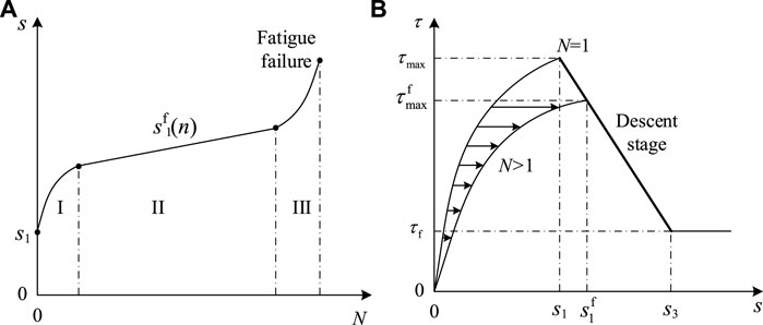
FIGURE 2. Bond behavior of reinforcing bars: (A) variation curve of slip with repeated cycles and (B) bond–slip relationship under fatigue loading.
From the perspective of energy dissipation, the fatigue loading process of materials is the same as that of static loading (Liu and Zhou, 2018). In the reinforced concrete structure, it is shown as follows: when the bond failure occurs between the reinforcement and the concrete for a certain number of repeated cycles, the maximum slip under fatigue loading is basically consistent with the slip value on the descending section of the bond stress–slip curve under pure static loading corresponding to the maximum bond stress. Therefore, the descending section of the bond–slip curve under static loading can be used to represent the envelope curve of the remaining bonding strength under fatigue load, as shown in Figure 2B.
In this section, the four-linear bond–slip model between concrete and reinforcing bars suggested in CEB-FIP Model Code 1990 (1993) was employed. The following relations give its analytical formulation:
where
Then the maximum bonding stress
At present, the degradation of strength or stiffness of stud connectors in steel–concrete composite structures under fatigue loading has been studied (Hanswille et al., 2007a). According to the experimental study in the literature (Hanswille et al., 2007b), the deformation behavior of stud connectors under fatigue loading is mainly characterized by increasing residual slip and elastic shear stiffness. The load–slip (Pn-δn) curve after n loading cycles can be expressed by the residual shear capacity Pu,n, in the following form:
The residual slip δstd,N between the stud and concrete after fatigue loading can be expressed as follows (Hanswille et al., 2007a):
where the coefficients C1 and C2 are given as follows:
Then the interface shear–slip (υn–δn) relationship at the beam–slab interface under fatigue loading can be given as follows:
After n loading cycles, the residual stiffness Ks,n of the stud connectors can be expressed as follows:
The residual shear capacity Pu,n can be determined by the following formula:
In the formulas given earlier, n denotes the number of repeated cycles; Nf is the fatigue life of studs; Kel,n is a constant, and it is equivalent to 1.41 (unit: mm−1); Kn = nsKs,n; p is the longitudinal spacing of the studs; Pu,0 and ΔP are the ultimate static strength and shear amplitude of the studs, respectively; ΔP = Pmax - Pmin; and Pmax and Pmin are the fatigue upper limit and fatigue lower limit of studs, respectively.
The fatigue stress state of the reinforcing bar in the concrete slab of composite beams under negative moment is basically the same as that of a reinforced concrete structure. With the increase of repeated cycles, the effective tensile area of the reinforcing bar will decrease, especially at the cracking location (Song, 2006). When the loss of cross-sectional area of the reinforcing bar in the process of fatigue loading conforms to Miner’s rule, the effective area of reinforcing bar at cracking position after n cycles can be determined by Eq. 21. Considering the degradation of the effective area of the reinforcing bar and the shear stiffness of studs under fatigue loading, an equation proposed by Fan and Nie (2005) can be modified and applied to the stress calculation of the reinforcing bar in the cracked section, which was defined as the following Eq. 22. In the equations given earlier, the parameters or coefficients can refer to the existing literature (Song et al., 2020). By solving Eq. 21 and Eq. 22, the cycle-dependent stress of the reinforcing bar can be obtained.
The mechanical approach to investigating the crack opening of a cracked beam is based on knowledge of the crack position (stabilized cracking) (Fabbrocino et al., 2007). Due to the randomness and complexity of the cracks’ development, the following two assumptions are made to simplify the model problem:
(1) The main crack occurs at the position of maximum bend.
(2) The profiles of cracks are linear triangular.
Each sub-element is defined between two adjacent cracks, that is, on the average crack spacing lc,r, as shown in Figure 3. The nodes for a sub-element discretization based on the finite difference method are also presented in Figure 3, as well as the details of the composite beams. According to a generic approach used in reinforcement concrete beams (Oliveira et al., 2008), the theoretical analysis of a sub-element can be referred to a sub-domain with a length of dx of the concrete slab, as shown in Figure 4, where the cases of the shear-slip behavior at the beam–slab interface and bond–slip behavior at the reinforcement–concrete interface are schematically reported together with some issues related to the boundary conditions. Then the axial force equilibrium of the bar and the cross-section under fatigue loading at a certain number of repeated cycles n can be expressed as follows:
where dσu(n) and dσb(n) are the stress increments under fatigue loading of reinforcement bars in the top layer and bottom layer, respectively; τfu and τfb are the bonding strengths under fatigue loading of reinforcement bars; du and db are the diameters of reinforcement bars; nu and nb are the numbers of reinforcement bars; dσc is the stress increments of the tension concrete under fatigue loading; Aeff is the effective tension area of the concrete slab; Afu and Afb are the areas of reinforcement bars under fatigue loading; dx is the length of the sub-domain of the concrete slab; and ∓ or ± depends on the position of the sub-domain.
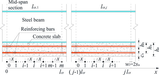
FIGURE 3. Sub-element discretization.
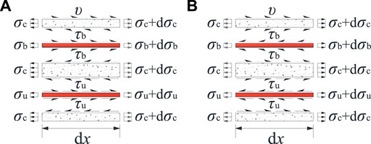
FIGURE 4. Translational equilibrium of the sub-domain: (A) in the left part of a sub-element and (B) in the right part of a sub-element.
According to Eqs 23, 24, the distribution coefficient of the tress increments of reinforcement bars can be defined as follows:
Based on assumption 2, the following equation is obtained:
where sfu and sfb are the slips of reinforcing bars in the top layer, and bottom layer, respectively; hu and hb are the distances of the beam–slab interface to reinforcing bars.
Then the stress increments of the tension concrete can be expressed as follows:
The stress variable in a sub-element depends on the relative slip between reinforcing bars and surrounding concrete, that is, the difference in longitudinal displacements between them. Thus, this description can be given as follows:
where us(x) and uc(x) are the longitudinal displacements of reinforcement bars and surrounding concrete, respectively; εs(x) and εc(x) are, respectively, the strains of reinforcement bars and surrounding concrete; εsh is the shrinkage strain of concrete, and εsh = 310µ is for this work according to China Code GB 50917-2013 (2013).
According to the division for the sub-element with small length Δx (see Figure 4), the finite difference forms of <b> Eqs 23, 28, 29 are as follows:
The values of σsu and σc in the i+1 section are determined from the values attained in the i section, by using the method of finite difference (Castel et al., 2012). Based on the bond–slip theory, the crack widths of steel–concrete composite beams under hogging moment can be expressed as follows:
The boundary conditions in the cracked section x=(j-1)lcr of each sub-element numbered j applied to Eqs 31–33 can be expressed as follows:
And the boundary condition at the abscissa x = jlcr established as the condition of convergence can be given in the following form:
Figure 5 shows the flowchart of the procedure for numerical solution. Through giving a tentative value ssu,0, it is possible to predict the crack widths along the composite beam corresponding to a certain loading level. The specific steps are as follows:
1) Input basic information and data of composite beam. Calculate the average crack spacing lcr according to Eq. 8. Divide a half-span structure into k sub-elements. Divide a sub-element into m sub-domains. Take the sub-element (i.e., numbered j) as the research object and input the repeated cycles n. Obtain the reinforcement stress σs,0(n) at the cracked section by combining Eq. 21 and Eq. 22. Calculate the concrete stress σc,0(n) = 0 at the cracked section by Eq. 34.
2) Assume the slip between the reinforcing bar and the concrete at the initial cracked section (i.e., the node number is i = 0) as an arbitrary value. Use Eq. 10 and Eq. 12 to modify Eq. 11, and obtain the bond–slip constitutive relation between the reinforcing bar and concrete under fatigue loading. Calculate the bond stress τfsu,i on sub-domain numbered i+1. Calculate the shear force υif of unit length at the beam–slab interface on sub-domain numbered i+1 by Eq. 18.
3) Calculate reinforcing bar stress σsu,i+1(n), concrete stress σcu,i+1(n) and the slip sfsu,i+1 between reinforcing bar and concrete by Eqs 30–32.
4) Set i = i+1 and repeat Step 3 until i = m, on the condition of the initial set of slip value ssu,0 and number of iterations of t = 1. Calculate the crack width according to Eq. 33 if the concrete stress σc,m = 0 or within the allowable error range, according to the control condition in Eq. 35. If σc,m ≠ 0 or the allowable error is exceeded, correct the initial slip value ssu,0 and continue the iterative operation of t = t+1 (i.e., repeat steps 2–4), until you get a reasonable value.
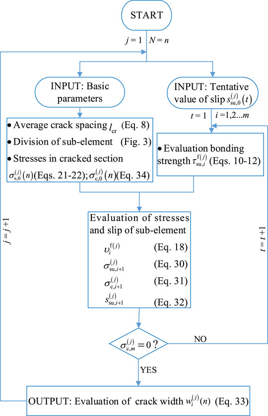
FIGURE 5. Flowchart of the numerical solution of crack width.
In order to obtain the experimental values of crack width in the negative moment regions of steel–concrete composite beams under fatigue loading, a total of three test beams were designed and manufactured. The specimens were placed upside down on two steel supports to simulate the action of a negative moment. Among them, the specimen numbered SCB1-1 was used for a static loading test, while the specimens numbered SCB1-2 and SCB1-3 were used for fatigue loading tests. Figure 6 shows the dimension details of the specimens. All test beams are equipped with stud connectors with a diameter, height, and spacing of 16 mm, 90 mm, and 100 mm, respectively. The ratio of longitudinal reinforcing bars is designed as 4.0% with a diameter of 16 mm. Material tests were conducted on concrete and steel before the formal loading of the specimens. The strength grade of the concrete was designed to be C50. The tensile reinforcement bars and steel plates used HRB400 and Q345, respectively (of the same factory batch). The axial tensile strength, elastic modulus, and the average result of compressive strength of concrete are 3.44 MPa, 3.47 × 10⁴ MPa, and 51.2 MPa, respectively. Meanwhile, the average results of the tensile yield strengths of the web (or top flange), bottom flange, and reinforcing bars are 443 MPa, 391 MPa, and 592 MPa, respectively. The setup of the fatigue test is illustrated in Figure 7. The fatigue load limits of SCB1-2 and SCB1-3 were designed as 25%Fu and 40%Fu, where Fu is the ultimate bearing capacity of SCB1-1 obtained from the static test. The loading ratio and frequency were set as 0.1 and 2 Hz, respectively. And the sine wave was used for the fatigue loading. The fatigue loading was suspended when the repeated cycles reached the specified times of 1 × 10⁴, 5 × 10⁴, 10 × 104, 50 × 104, 100 × 104, 150 × 104, 200 × 104, and 250 × 104. Then the static loading test was performed to measure the crack width by an electronic crack width measurement instrument. The typical experimental results are listed in Table 3, in which ΔF is the fatigue load amplitude, that is, Fmax−Fmin; Fcr is the cracking load in a static test; Nf is the fatigue life. The typical pattern of crack development is shown in Figure 8.
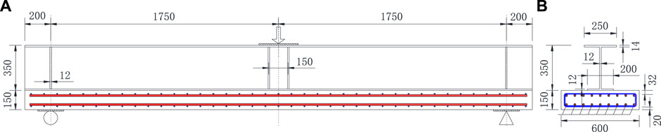
FIGURE 6. Dimension details of the test specimen (unit: mm): (A) front elevation and (B) side elevation.
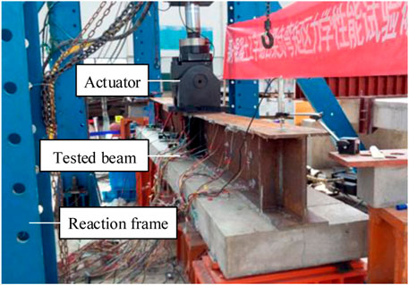
FIGURE 7. Fatigue test setup.
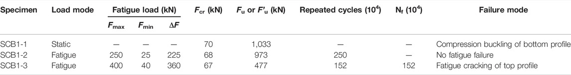
TABLE 3. Typical experimental results.
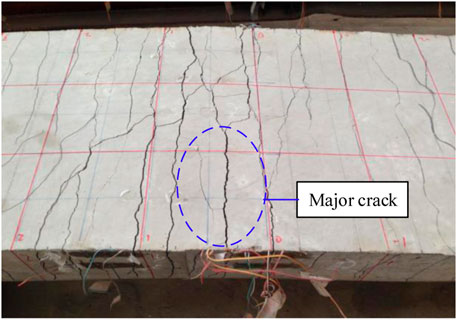
FIGURE 8. Typical crack development pattern.
The relative slip between the reinforcing bar and concrete increases gradually under the action of fatigue load, resulting in the growth of crack width with repeated cycles. At present, there is no specific method to calculate the crack width in the negative moment regions of composite beams under fatigue loading. For reinforced concrete structures, the crack width under fatigue loading is generally expressed by the method under static loading through appropriate correction, that is, the experimental regression formula obtained by using the initial crack expansion coefficient (Song, 2006). According to the test results, a statistical empirical formula was given for the maximum crack width after n loading cycles:
where, ω0 is the initial maximum crack width, which can be calculated according to the conventional method under static loading. In this study, it is calculated according to the recommended formula in JTG D62-2004 (2004), which is expressed as follows:
where Ap is the area of prestressed reinforcement in the tensile zone; bf and hf are the width and thickness of the tensile concrete slab; C1´ = 1.0 is for the deformed bar; C2´ = 1.0 is for load effect; C3´ = 1.2 is for the axial tension members.
In GB 50010-2010 (2010), the non-uniform coefficient φ of tensile rebar strain for reinforced concrete specimens under fatigue loading is equivalent to 1.0, that is, the bond between the rebar and the concrete fails completely, considering the fatigue effect. The calculation method is proposed based on the assumptions that the fatigue failure occurs in reinforced concrete structures or the loading cycles reaches 200 × 104, and the maximum crack width can be expressed as follows:
where αcr is the characteristic coefficient of tension members under the action of force; ftk is the standard value of concrete tensile strength; for other coefficients, refer to the explanation given before.
Figure 9 shows the load–crack width response of the experimental test, the existing calculation methods, and the proposed model in this study. It can be found that the crack width measured in the test increased with the repeated cycles. It developed rapidly in the early loading process of about 10 × 104 cycles, and then grew slowly. The crack width calculated according to Eq. 36 had a large deviation from the test results at different times of cyclic loading. The results of the maximum crack width by Eq. 39 were limited to a particular condition. In addition, the calculated values were not universal for the structure checking and were not in good agreement with the test results. As for the numerical model in this study, which fully takes the characteristics of the negative moment regions of composite beams into consideration, the computed results are in good agreement with the experimental values. And the accuracy was further verified by the tested values from other literature (Lin et al., 2013), as shown in Figure 10. As a result, the numerical model can well reflect the development trend of crack width in the process of fatigue loading and provide a reference for anti-fatigue design and checking calculation of composite beam in negative moment region.
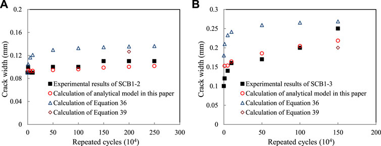
FIGURE 9. Comparison between calculated and tested values of crack width under fatigue loading: (A) SCB1-2 and (B) SCB1-3.
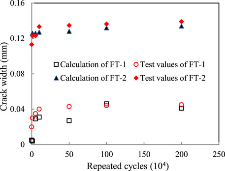
FIGURE 10. Verification of the calculation model with a fatigue test conducted by Lin et al. (2013).
In this study, a modified formula for average crack spacing and a numerical model for crack width in hogging moment regions of steel–concrete composite beams under fatigue loading are presented. Meanwhile, an experimental test is designed and conducted to obtain the crack width at certain repeated cycles. Then the accuracy of the proposed analytical models is validated through the comparison between the proposed models and test results. The main conclusions drawn are as follows:
(1) The modified formula of average crack spacing takes the spacing of transverse reinforcement into account through the analysis and discussion of existing equations. By comparison, the modified formula shows more reasonable results.
(2) The analytical model for crack width under repeated loading includes the explicit formulations of slip at both the beam–slab interface and the reinforcement–concrete interface, as well as reinforcement stress in the cracked section considering fatigue effect. The analytical results can be obtained by using a suitable numerical procedure.
(3) Compared with the empirical formulas for crack width under fatigue loading based on the axial tension members in existing literature, the analysis results of the numerical model show more reasonable agreement with the measured values of the experimental beams conducted in this study. For engineering design and application, the work in this study can provide a reference for calculation and evaluation in the negative moment regions of steel–concrete composite beams under fatigue loading.
The original contributions presented in the study are included in the article/Supplementary Material, further inquiries can be directed to the corresponding authors.
AS conceived the work and wrote the manuscript. AS, HX, and QL developed the analytical model. SW analyzed the results and revised the manuscript. All authors read and agreed to the published version of the manuscript.
This research was sponsored by the school-level research project of Yancheng Institute of Technology (No. xjr2021007). QL acknowledges the National Natural Science Foundation of China (No. 52108269) and the Scientific and Technology Research Program of the Chongqing Municipal Education Commission (No. KJQN202100716).
The authors declare that the research was conducted in the absence of any commercial or financial relationships that could be construed as a potential conflict of interest.
All claims expressed in this article are solely those of the authors and do not necessarily represent those of their affiliated organizations, or those of the publisher, the editors, and the reviewers. Any product that may be evaluated in this article, or claim that may be made by its manufacturer, is not guaranteed or endorsed by the publisher.
BS EN 1992 Eurocode 2 (2004). Design of Composite concrete Structure. Brussels, Belgium: European Committee for Standardization.
BS EN 1994-2 (2005). Eurocode 4: Design of Composite Steel and concrete Structures, Part 2: General Rules and Rules for Bridges. Brussels, Belgium: European Committee for Standardization.
Castel, A., Vidal, T., and François, R. (2012). Finite-element Modeling to Calculate the Overall Stiffness of Cracked Reinforced concrete Beams. J. Struct. Eng. 138 (7), 889–898. doi:10.1061/(ASCE)ST.1943-541X.0000520
CEB-FIP Model Code 1978 (1978). CEB-FIP Model Code 1978. Lausanne, Switzerland: Comite Euro-International du Beton, Thomas Telford Ltd.
CEB-FIP Model Code 1990 (1993). CEB-FIP Model Code 1990. Lausanne, Switzerland: Comite Euro-International du Beton, Thomas Telford Ltd.
Chen, S., Wang, X., and Jia, Y. (2009). A Comparative Study of Continuous Steel-concrete Composite Beams Prestressed with External Tendons: Experimental Investigation. J. Constructional Steel Res. 65 (7), 1480–1489. doi:10.1016/j.jcsr.2009.03.005
El-Shihy, A. M., Fawzy, H. M., Mustafa, S. A., and El-Zohairy, A. A. (2010). Experimental and Numerical Analysis of Composite Beams Strengthened by CFRP Laminates in Hogging Moment Region. Steel Compos. Structures 10 (3), 281–295. doi:10.12989/scs.2010.10.3.281
El-Zohairy, A., Salim, H., Shaaban, H., Mustafa, S., and El-Shihy, A. (2017). Experimental and FE Parametric Study on Continuous Steel-concrete Composite Beams Strengthened with CFRP Laminates. Construction Building Mater. 157, 885–898. doi:10.1016/j.conbuildmat.2017.09.148
Fabbrocino, G., Verderame, G. M., and Polese, M. (2007). Probabilistic Steel Stress-Crack Width Relationship in R.C. Frames with Smooth Rebars. Eng. Structures 29 (1), 1–10. doi:10.1016/j.engstruct.2006.04.002
Fan, J., Gou, S., Ding, R., Zhang, J., and Shi, Z. (2020). Experimental and Analytical Research on the Flexural Behaviour of Steel-ECC Composite Beams under Negative Bending Moments. Eng. Structures 210 (1), 110309.1–110309.17. doi:10.1016/j.engstruct.2020.110309
Fan, J., and Nie, J. (2005). Effects of Slips on Load-Carrying Capacity of Composite Beams under Negative Bending. Eng. Mech. 22 (3), 177–182. doi:10.3969/j.issn.1000-4750.2005.03.031
GB 50010-2010 (2010). Code for Design of concrete Structures. Beijing, China: Ministry of Construction of China.
GB 50917-2013 (2013). Code for Design of Steel and concrete Composite Bridges. Beijing, China: Ministry of Construction of China.
GBJ 10-89 (1989). Code for Design of concrete Structures. Beijing, China: Ministry of Construction of China.
Han, J., Song, Y., and Chang, J. (2014). Analysis Model of Crack Width of Partially Prestressed concrete Beams under Fatigue Loading. J. Cent. South Univ. (Science Technology) 45 (11), 3977–3985. JournalArticle/5b433a76c095d716a4bf90c3.
Hanswille, G., Porsch, M., and Ustundag, C. (2007a). Resistance of Headed Studs Subjected to Fatigue Loading. J. Constructional Steel Res. 63 (4), 475–484. doi:10.1016/j.jcsr.2006.06.035
Hanswille, G., Porsch, M., and Ustundag, C. (2007b). Resistance of Headed Studs Subjected to Fatigue Loading Part II: Analytical Study. J. Constructional Steel Res. 63 (4), 485–493. doi:10.1016/j.jcsr.2006.06.036
He, J., Liu, Y., Chen, A., and Yoda, T. (2010). Experimental Study on Inelastic Mechanical Behaviour of Composite Girders under Hogging Moment. J. Constructional Steel Res. 66 (1), 37–52. doi:10.1016/j.jcsr.2009.07.005
Hou, W., Luo, R., and Ye, M. (2001). On Crack Width of Steel Cast-In-Place concrete Composite Beams with High Reinforcement Ratio. China Railway Sci. 22 (5), 54–60. doi:10.3321/j.issn:1001-4632.2001.05.009
JTG D62-2004 (2004). Code for Design of Highway Reinforced concrete and Prestressed concrete Bridges and Culverts. Beijing, China: Ministry of Communication of China.
Lin, W., Yoda, T., and Taniguchi, N. (2013). Fatigue Tests on Straight Steel-concrete Composite Beams Subjected to Hogging Moment. J. Constructional Steel Res. 80 (1), 42–56. doi:10.1016/j.jcsr.2012.09.009
Liu, F., and Zhou, J. (2018). Experimental Research on Fatigue Damage of Reinforced Concrete Rectangular Beam. KSCE J. Civ. Eng. 22 (9), 3512–3523. doi:10.1007/s12205-018-1767-y
Liu, J., Ding, F.-x., Liu, X.-m., and Yu, Z.-w. (2016). Study on Flexural Capacity of Simply Supported Steel-concrete Composite Beam. Steel Compos. Struct. 21 (4), 829–847. doi:10.12989/scs.2016.21.4.829
Luo, Q., Liu, D., Qiao, P., Zhou, Z., Zhao, Y., and Sun, L. (2020). Micro-CT-based Micromechanics and Numerical Homogenization for Effective Elastic Property of Ultra-high Performance concrete. Int. J. Damage Mech. 29 (1), 45–66. doi:10.1177/1056789519848475
Manfredi, G., Fabbrocino, G., and Cosenza, E. (1999). Modeling of Steel-concrete Composite Beams under Negative Bending. J. Eng. Mech. 125 (6), 654–662. doi:10.1061/(asce)0733-9399(1999)125:6(654)
Manfredi, G., and Pecce, M. (1998). A Refined R.C. Beam Element Including Bond-Slip Relationship for the Analysis of Continuous Beams. Comput. Structures 69 (1), 53–62. doi:10.1016/S0045-7949(98)00078-9
Nie, J., and Zhang, M. (1997). Study on the Crack of concrete Flange in Tension of Composite Steel-concrete Beams. J. Tsinghua Univ. Sci. Technol. 37 (6), 95–99. doi:10.3321/j.issn:1000-0054.1997.06.004
Oliveira, R. S., Ramalho, M. A., and Corrêa, M. R. S. (2008). A Layered Finite Element for Reinforced concrete Beams with Bond-Slip Effects. Cement and Concrete Composites 30 (3), 245–252. doi:10.1016/j.cemconcomp.2007.09.007
Qin, F., Zhang, Z., Yin, Z., Di, J., Xu, L., and Xu, X. (2020). Use of High Strength, High Ductility Engineered Cementitious Composites (ECC) to Enhance the Flexural Performance of Reinforced concrete Beams. J. Building Eng. 32, 101746. doi:10.1016/j.jobe.2020.101746
Ramm, W., and Elz, S. (2002). “Composite Construction in Steel and Concrete IV,” in Proceedings of Composite Construction in Steel and Concrete IV Conference (Fairfax, America: ASCE Press). doi:10.1061/9780784406168
Ryu, H.-K., Chang, S.-P., Kim, Y.-J., and Kim, B.-S. (2005). Crack Control of a Steel and concrete Composite Plate Girder with Prefabricated Slabs under Hogging Moments. Eng. Structures 27 (11), 1613–1624. doi:10.1016/j.engstruct.2005.05.015
Ryu, H.-K., Kim, Y.-J., and Chang, S.-P. (2007). Crack Control of a Continuous Composite Two-Girder Bridge with Prefabricated Slabs under Static and Fatigue Loads. Eng. Structures 29 (6), 851–864. doi:10.1016/j.engstruct.2006.06.021
Ryu, H.-K., Shim, C.-S., Chang, S.-P., and Chung, C.-H. (2004). Inelastic Behaviour of Externally Prestressed Continuous Composite Box-Girder Bridge with Prefabricated Slabs. J. Constructional Steel Res. 60 (7), 989–1005. doi:10.1016/j.jcsr.2003.09.004
Song, A., Li, Z., Xu, H., Wan, S., and Zhou, P. (2021). Numerical Calculation Model of Crack Width in Negative Moment Regions of Steel⁃concrete Composite Beams. J. Harbin Inst. Technol. 53 (3), 75–81. doi:10.11918/201912134
Song, A., Luo, Q., Wan, S., and Li, Z. (2020). Experimental and Analytical Study on Deformation Behavior in Hogging Moment Regions of Composite Beams. Adv. Civil Eng. 2020 (3), 1–10. doi:10.1155/2020/6630742
Song, Y. P. (2006). Fatigue Behavior and Design Principle of Concrete Structures. Beijing, China: China Machine Press.
Su, Q.-T., Yang, G.-T., and Wu, C. (2012). Experimental Investigation on Inelastic Behavior of Composite Box Girder under Negative Moment. Int. J. Steel Struct. 12 (1), 71–84. doi:10.1007/s13296-012-1007-0
Sun, Q., Yang, Y., Fan, J., Zhang, Y., and Bai, Y. (2014). Effect of Longitudinal Reinforcement and Prestressing on Stiffness of Composite Beams under Hogging Moments. J. Constructional Steel Res. 100 (13), 1–11. doi:10.1016/j.jcsr.2014.04.017
Wang, B., Huang, Q., Liu, X., and Li, W. (2018). Experimental Investigation of Steel-Concrete Composite Beams with Different Degrees of Shear Connection under Monotonic and Fatigue Loads. Adv. Struct. Eng. 21 (2), 227–240. doi:10.1177/1369433217717121
Wang, W., Zhang, X.-d., Zhou, X.-l., Wu, L., and Zhu, H.-j. (2021). Study on Shear Behavior of Multi-Bolt Connectors for Prefabricated Steel-concrete Composite Beams. Front. Mater. 8, 625425. doi:10.3389/fmats.2021.625425
Wu, Z., Chen, H., Gao, X., and Zhu, P. (1993). Experimental Study on Crack Width of concrete Slab of Composite Beams under Negative Bending. J. Harbin Architecture Civil Eng. Inst. 26 (1), 58–62.
Yu, Z., and Guo, F. (2004). Experimental Study of Crack Width in Negative Bending Region of Partially Prestressed Continuous Steel concrete Composite Beams. J. Building Structures 25 (4), 55–59. doi:10.3321/j.issn:1000-6869.2004.04.008
Zanuy, C., Albajar, L., and de la Fuente, P. (2010). On the Cracking Behaviour of the Reinforced concrete Tension Chord under Repeated Loading. Mater. Struct. 43 (5), 611–632. doi:10.1617/s11527-009-9516-9
Zhang, W., Ye, Z., Gu, X., and Li, S. (2017). Assessment of Fatigue Life for Corroded Reinforced concrete Beams under Uniaxial Bending. J. Struct. Eng. 143 (7), 04017048 1–14. doi:10.1061/(asce)st.1943-541x.0001778
Zhang, Y., Fan, J., and Li, Y. (2011). Law of Crack Development and Calculation of Crack Width of Continuous Composite Beams. Eng. Mech. 28 (7), 84–90. doi:10.1080/0144929X.2011.553739
Zhang, Z., Liu, D., Ding, Y., and Wang, S. (2022). Mechanical Performance of Strain-Hardening Cementitious Composites (SHCC) with Bacterial Addition. J. Infrastruct. Preserv. Resil. 3 (3). doi:10.1186/s43065-022-00048-3
Keywords: steel–concrete composite beam, hogging moment region, fatigue, crack width, numerical model
Citation: Song A, Xu H, Wan S and Luo Q (2022) Analytical Model of Crack Width in Hogging Moment Regions of Steel–Concrete Composite Beams Under Fatigue Loading. Front. Mater. 9:859687. doi: 10.3389/fmats.2022.859687
Received: 21 January 2022; Accepted: 04 March 2022;
Published: 07 April 2022.
Edited by:
Zhigang Zhang, Chongqing University, ChinaCopyright © 2022 Song, Xu, Wan and Luo. This is an open-access article distributed under the terms of the Creative Commons Attribution License (CC BY). The use, distribution or reproduction in other forums is permitted, provided the original author(s) and the copyright owner(s) are credited and that the original publication in this journal is cited, in accordance with accepted academic practice. No use, distribution or reproduction is permitted which does not comply with these terms.
*Correspondence: Hongtao Xu, eGh0MTk3OEBoZWJ1c3QuZWR1LmNu; Shui Wan, c2V1ZnJwYnJpZGdlQDE2My5jb20=
Disclaimer: All claims expressed in this article are solely those of the authors and do not necessarily represent those of their affiliated organizations, or those of the publisher, the editors and the reviewers. Any product that may be evaluated in this article or claim that may be made by its manufacturer is not guaranteed or endorsed by the publisher.
Research integrity at Frontiers
Learn more about the work of our research integrity team to safeguard the quality of each article we publish.