 Aiming Song
 Hongtao Xu2*
 Qi Luo
94% of researchers rate our articles as excellent or good
Learn more about the work of our research integrity team to safeguard the quality of each article we publish.
Find out more
ORIGINAL RESEARCH article
Front. Mater., 31 May 2022
Sec. Structural Materials
Volume 9 - 2022 | https://doi.org/10.3389/fmats.2022.859663
This article is part of the Research TopicAdvanced Concretes and Their Structural ApplicationsView all 23 articles
This work studies the improvement in the inelastic mechanical property of steel-concrete composite beams strengthened by carbon-fiber-reinforced polymer (CFRP) laminates under a negative moment. First, the monotonic loading test was designed and performed on an inverted simply supported beam to simulate the negative moment regions of continuous composite beams. Second, the finite element analysis (FEA) on flexural capacity and cracking resistance in negative moment regions of the composite beams was carried out with ANSYS software. A series of mechanical indexes including the load-deflection curve, component strain, and crack propagation were obtained from the FEA model and verified through the test data. The results showed that the FEA model can accurately predict the general mechanical behavior of composite beams under negative moments, and the calculation results considering the interface slip effect were closer to the experimental values. Finally, based on the FEA model, the parametric study on static behavior in negative moment regions of composite beams strengthened with/without CFRP laminates was conducted. The effects of the CFRP layout width, layout position, layer number, longitudinal reinforcement ratio, and shear connection degree on the bearing capacity of the composite beams were considered. The CFRP laminates can effectively improve the bending resistance of composite beams under negative moments. At a low reinforcement ratio, the bearing capacity was greatly affected by the layout width and layer number of the CFRP laminates, but the rate of increase was not significant when the layer number was more than 3. The reinforcement ratio had a great influence on the bearing capacity of composite beams under negative moments, but the influence of the shear connection degree was not remarkable.
In recent decades, new materials or structures have been widely used in civil engineering (Qin et al., 2020; Zhang et al., 2021; Zhang et al., 2022; Lin et al., 2022). As a relatively new form of construction in China, steel-concrete composite structures have been popularized in bridge engineering because of the full use of properties of the two materials (Wang et al., 2017; Wang et al., 2021). However, steel-concrete continuous composite beams have problems such as concrete cracking and compression buckling of the bottom profile under a low static load level due to the existence of a negative moment at the middle support position (Hamoda et al., 2017). In recent decades, considerable research has focused on the static behavior of composite beams under negative moments with experimental tests (Song et al., 2018; Fan et al., 2020), theoretical methods (Fan, 2003; Nguyen et al., 2009), and numerical calculations (Chen et al., 2011; Lin and Yoda, 2014). At present, the calculation and analysis methods have tended to be mature and can serve the design well. Compared with traditional building materials such as steel, reinforcing bar, and concrete, carbon-fiber-reinforced polymers (CFRPs) have excellent properties of lightweight, high strength, and corrosion and fatigue resistance, and they has been widely used in the construction and reinforcement of engineering structures. Studies showed that reinforced concrete structures (Hawileh et al., 2013; Hawileh et al., 2014), steel beam structures (Teng et al., 2015; Ghafoori et al., 2015), and steel-concrete composite structures (Tavakkolizadeh and Saadatmanesh, 2003; Karam et al., 2017) can be effectively improved in terms of flexural bearing capacity, fatigue life, and cracking performance after strengthening with CFRP laminates.
The nonlinear static behavior of defective curved steel beams strengthened by CFRP laminates was studied using the ANSYS software, and the results of the analysis showed that the utilization of CFRP laminates for strengthening the curved beams could recover the lost strength to some extent (Keykha, 2019). The model test and finite element analysis (FEA) of composite beams with CFRP laminates in negative moment regions were carried out to study the flexural mechanical behavior and cracking resistance, and the results showed that the introduction of CFRP laminates can effectively improve the cracking performance and bearing capacity (El-Zohairy et al., 2017). The flexural behavior of pre-damaged steel-concrete composite beams reinforced with CFRP laminates was studied through the experimental test of 10 beams, and the mechanical properties could be restored at a certain proportion. Meanwhile, the use of mechanical anchors in the pre-damaged steel-concrete composite beams could improve the structural strength, obviously (Karam et al., 2017). To analyze the flexural strength of steel-concrete composite beams strengthened with a pre-stressed CFRP plate, an analytical solution was proposed by applying experimental and finite element methods, and it was found that the stiffness and strength of steel-concrete composite beams could be improved effectively by using CFRP plates, and the FEA results were in good agreement with the test results (Deng et al., 2011). The flexural performance of steel beams reinforced with anchored hybrid composites was analyzed and discussed, and the multiple influencing parameters involved in the length of fiber-reinforced polymers (FRPs), the thickness of the FRP, and the number of anchors were investigated in detail (Sweedan et al., 2016).
Although some studies have been done to explore the mechanical behavior of steel-concrete composite beams strengthened by CFRP laminates, most of the CFRP laminates were bonded to steel beams under positive moments. There are few reports focusing on the influence of CFRP reinforcement technology on the mechanical properties and cracking control in composite beams under negative moments. In addition, the FEA theory has become an important way to study the mechanical mechanism of structures in recent years. By establishing a fine FEA model, the reliability of the model test and theoretical analysis can be verified, and the application scope of experimental and theoretical methods can be further extended to the analysis of the mechanical behavior of complex structures under various actions (Fan, 2003). It is difficult to analyze the whole process of structural loading according to the traditional method, because of the significant nonlinear characteristics of composite beams under the action of negative moments. At this point, the FEA method can be used to analyze the inelastic mechanical properties of the structure.
This study is to understand the inelastic mechanical behavior of steel-concrete composite beams upgraded with CFRP laminates under negative moments. To simulate the negative moment regions of continuous composite beams, a monotonic loading test is performed on a plain beam in an inverted simply supported position. An FEA model is developed and validated through the test results with ANSYS software, and a series of mechanical indexes, such as load-deflection curve and component strain, are obtained. Based on the FEA model, CFRP laminates are introduced to strengthen the concrete slab, and the mechanical properties of composite beams under negative moments strengthened with/without CFRP laminates are compared and analyzed. Through the parametric analysis, the influences of the CFRP layout width, layout position, layer number, longitudinal reinforcement ratio, and shear connection degree on the bearing capability of structures are determined. It is expected to provide a reference for practical engineering design and application of such structures.
Considering the characteristics of negative moments at the bearing position of continuous composite beam bridges in practical engineering, an inverted simply supported beam is designed and performed in this study to simulate this region. The dimension details of the test beam are shown in Figure 1. The total longitudinal length of the specimen is 3,900 mm and the calculated span is 3,500 mm. The height of the specimen is 500 mm, consisting of the concrete slab with a thickness of 150 mm and an I-beam with the height of 350 mm. The width of the concrete slab is 600 mm and the concrete strength grade is C50. The HRB400 hot-rolled ribbed steel bars are used in the concrete slab, of which the longitudinal and transverse diameters are 16 and 10 mm, respectively. The ratio of the longitudinal reinforcing bars is 4.0%. The grade of the whole steel beam adopts Q345, and the thicknesses of the web, top flange, and bottom flange are 12 mm, 12, and 14 mm, respectively. The interface between the steel beam and the concrete slab is equipped with stud connectors to resist longitudinal shear force. The shear connection degree of the test beam is designed to be 0.95 with a diameter, height, and spacing of 16, 90, and 100 mm, respectively. The set-up of the static test is shown in Figure 2.

FIGURE 1. Dimension details of the test specimens (unit: mm): (A) front elevation; (B) side elevation.

FIGURE 2. Static test set-up.
The compressive strength of the concrete cube is tested according to relevant regulations before the loading test. According to the test results, the averages of the cube compressive strength and axial tensile strength are 51.2 and 3.44 MPa, respectively. In addition, three tensile specimens are taken from tensile steel bars with a diameter of 16 mm and from steel plates with a thickness of 12 and 14 mm, respectively, and then the steel properties are tested. The average values of the tensile yield strength of the rebars, web (or top flange), and bottom flange of the steel beams are 592, 443, and 391 MPa, respectively. The average values of the ultimate tensile strength are 718, 608, and 520 MPa, respectively. All the material properties are shown in Table 1.
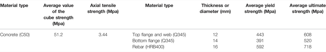
TABLE 1. Material properties of the specimen materials.
Steel-concrete composite beams are composed of different materials, and the mechanical behavior depends on the properties of each material and the interaction between each member. It is difficult to study the whole loading process of the composite structure by the traditional analytical method because of the significant nonlinear characteristics after the cracking of the concrete slab under the action of negative moments. In addition, the model test has certain limitations such as the high cost of manpower, material resources, and financial resources. Then, the FEA method can be used to analyze the mechanical properties of the steel-concrete composite beams under negative moments and the inelastic strengthened beams bonded with the CFRP.
The concrete slab is modeled by using a three-dimensional (3D) solid element SOLID65, which has the effects of tensile cracking and compression crushing. This type of element is defined by eight nodes and each node has 3°of freedom. The steel beam is simulated by using a SHELL43 element, each node of which has 6°of freedom of translation and rotation. This element has the characteristics of plasticity, creep, stress rigidness, large deformation, large strain, and element of life and death. The steel block at the loading position is developed by the SOLID45 element, with the characteristics of plasticity, creep, expansion, stress hardening, large deformation, large strain, and initial stress input. The number of nodes and degrees of freedom in SOLID45 are identical to those in SOLID65. The longitudinal reinforcing bars are simulated by a 3D truss element LINK8, each node of which has 3°of freedom. This type of element can bear axial tension and compression but not bending moment, with the characteristics of plasticity, creep, stress rigidification, and large deformation. A non-linear spring element COMBINE39 is used to simulate the longitudinal shear behavior of the stud connectors. The element has unidirectional characteristics with a nonlinear generalized force-deformation curve, and each node has 3°of freedom. At present, the element types used to simulate CFRP laminates include SOLID46 with layered structure characteristics and SHELL41 with membrane characteristics. In addition to the characteristics mentioned previously, SOLID46 allows more than 250 layers of different materials, with stress hardening and large deformation properties. SHELL41 is defined by four nodes, each of which has 3°of freedom. This type of element only has the plane inner membrane stiffness but no out-of-plane bending stiffness. It has the characteristics of stress rigidness, large deformation, non-linearity, and element of life and death. According to the contrast, the mechanical properties of SHELL41 are more consistent with the loading state of CFRP laminates in structural reinforcement. Thus, this element is used to simulate CFRP laminates in the modeling process of this study.
When the load acting on the composite beam is in the normal service stage, the slip between the steel and concrete is negligible compared with the slip between the steel beam and concrete slab (Nie et al., 2004). Therefore, it can be assumed that a good bond relationship exists between reinforcement and the concrete, and the coupling of node degrees of freedom is adopted in modeling. When CFRP laminates are introduced to strengthen the concrete slab of composite beams, high strength epoxy resin is usually used as a reliable adhesion agent, which can better realize the bond between the CFRP laminates and the concrete slab. Thus, it is also assumed that CFRP laminates and the concrete slab are perfectly bonded during the establishment process of the FEA model. The existing literature shows that the phenomenon of lifting will be produced between the steel beam and the concrete slab under the action of the load, and a certain tension will be generated in the studs. However, compared with the longitudinal slip, this phenomenon has little effect on the overall performance of composite beams. Therefore, the lateral and vertical degrees of freedom of the adjacent nodes at the interface between the top flange of the steel beam and the concrete slab are coupled to achieve the purpose of ignoring the lifting effect (Fan, 2003). The final FEA model is shown in Figure 3.
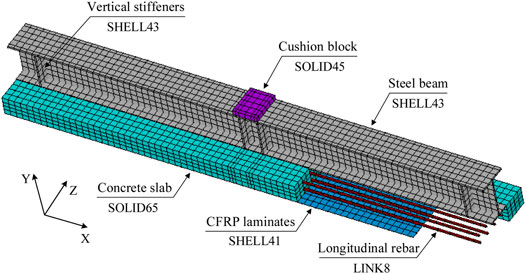
FIGURE 3. Establishment of the finite element model.
In this study, the classic Hognestad model (Hognestad, 1951) is adopted to represent the stress-strain constitutive relationship of concrete, as shown in Figure 4. During the developing process of the FEA model, the multi-linear isotropic strengthening model (MISO) is used to define the curve. From Figure 4, we can see that a descending section existed in the stress-strain curve of the concrete in the tension process. But different from the case of compression, it is generally considered that the concrete is damaged when it reaches the ultimate tensile strength. Thus, only the ascending section of the straight line in the tensile process is considered. During the FEA, the axial tensile strength ft′ can be obtained from the axial compressive strength of the cylinder fc′ by using the following conversion relation:
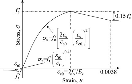
FIGURE 4. Stress-strain constitutive relation of the concrete.
Considering the elasticity and strengthening characteristics of the stress-strain curves of the steel, the bilinear kinematic strengthening model (BKIN) is used to simulate the constitutive relationship of steel beams or reinforcing bars during the modeling process, as shown in Figure 5. From Figure 5, we can see that the stress-strain curve will be simplified to a gentle oblique line after the steel reaches the yield point fy. To ensure the convergence of model calculation, the strengthening modulus Es’ is uniformly taken as 1/20,000 of the elastic modulus Es by referring to the selection method in the literature (Fan, 2003), and the constitutive curves under tension and compression are assumed to be the same. In addition, the ultimate tensile strain of longitudinal tensile reinforcement is equivalent to 0.01 in this study (GB 50010-2010, 2010).

FIGURE 5. Stress-strain constitutive relation of the rebar.
For stud connectors, various shear-slip curves have been proposed. The calculation method in this study adopts the highly recognized exponential model proposed by Ollgaard et al. (1971) as shown in Figure 6, and the specific form is as follows:
where, Q is the shear force of the studs; s is the slip generated at the welding position of the studs; Qu is the ultimate shear bearing capacity of studs; and
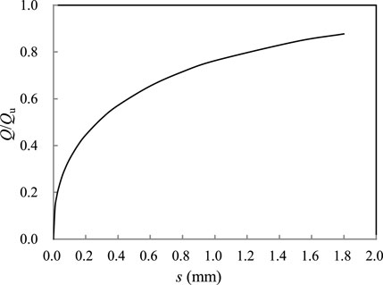
FIGURE 6. Shear-slip relationship of stud connectors.
When reaching the ultimate tensile stress, the CFRP laminates will fracture directly, and the stress immediately drops to 0. The ultimate tensile strain of the CFRP laminates is generally 0.015–0.02. In this study, it is assumed that CFRP laminates are an ideal linear elastic material with a designed thickness of 0.167 mm. The tensile elastic modulus, the ultimate tensile strength, and the Poisson ratio are equivalent to 2.2 × 10⁵ MPa, 3,200 MPa, and 0.2, respectively.
Based on the static test performed previously, an FEA model is established and verified in this section. It is worth explaining that the load-deflection curve of a structure generally includes a rising section and a descending section, and the latter is related to the ductility of the structure. However, the maximum deformation in the FEA is difficult to realize because of the low convergence and accuracy in the simulation calculation. Therefore, this study focuses on the failure state of the component corresponding to the peak load, and does not consider the maximum deformation of the descending section. The comparison result of calculated and tested values of the load-deflection curve is shown in Figure 7. The two calculation curves by the FEA model take into account two working conditions with slip and without slip effects between the concrete and the steel beam. When interface slip is considered, a spring element COMBINE39 is used to simulate the shear performance of the studs. When interface slip effect is not considered, the freedom degrees of nodes in the contact interface between the concrete and the top flange plate are coupled. As can be seen from the figure, the influence of interface slip effects can be ignored before the service load (50% Fu), because the finite element calculation results of the two cases coincide well. When the structure enters the elastic-plastic stage, the slip effect has a certain influence on the mechanical properties of the structure, mainly in the smaller flexural stiffness with considering the slip effect than that without considering. But the slip has little influence on the ultimate bearing capacity of composite beams. In addition, the bending stiffness obtained by the FEA model is higher than the experimental value, especially in the nonlinear stage. The assumption of a perfect bond between reinforcement and the concrete in the modeling process and the neglect of the weakening effect of shear connectors in concrete slabs are the main reasons for the difference in the results. But from the overall trend, the load-deflection curve calculated by the finite element is in good agreement with the experimental data, and the calculated results considering the interface slip effect are closer to the experimental values. The influence of the slip effect is considered in the FEA of the following contents.
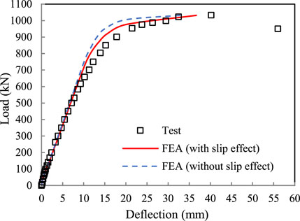
FIGURE 7. Comparison of calculated and tested values of the load-deflection curve.
The comparison of calculated and tested values of the test beam at the characteristic points are shown in Table 2, including the cracking state of the concrete slab, the normal limit state of the beam when the deflection reached the ultimate value (i.e., L/600), and the states of the compressive yield of the bottom profile, the tensile yield of longitudinal reinforcing bars, and the limit state of structure bearing capacity. L/600, fsy, fry, and fu in Table 2 represent deflections at the mid-span of each aforementioned stage, respectively. It can be seen from the table that the model calculation results of load or deflection at each characteristic point are quite consistent with the test values. Especially for the load, the error between the calculated and tested values is basically within 5%. It shows that the FEA model in this study can obtain an accurate inelastic mechanical behavior of a composite structure under negative moments.
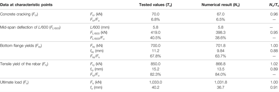
TABLE 2. Comparison of calculated and tested values at characteristic points.
In the FEA model, the strain of the bottom profile at the loading position is affected by the cushion block. Thus, the strain curves at the bottom of the web and the middle of the top steel profile are selected and compared with the experimental values. For the strain curve of the reinforcing bar, the main tension bar closest to the web of the steel beam at mid-span is selected as the research object. The comparison results of load-strain calculation curves and test values of the steel beam and the reinforcing bar are shown in Figure 8. It can be seen from the figure that the calculated strain of the steel beam is in good agreement with the experimental values. Because of the influence of concrete cracking, there is some deviation between the calculated and the experimental results after the structure enters the yield stage. But in general, the FEA model accurately simulates the loading process of the inverted composite beams. The results show that the reinforcing bars and steel beams in the negative moment region can work well together and give full play to their plastic deformation abilities.
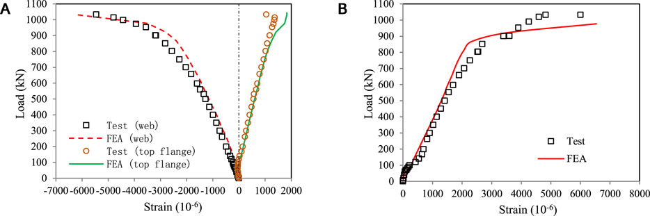
FIGURE 8. Comparison of calculated and tested values of strain in the steel beam and the rebar: (A) strain curves of the steel beam; (B) strain curves of the rebar.
Figure 9 shows the Mises equivalent stress cloud at the yield load of the bottom steel profile (701.8 kN). As can be seen from the figure, the maximum compressive stress of the steel beam occurs at a position about 20 cm away from the loading point, due to the existence of vertical stiffeners. At this moment, the maximum compressive strain reaches about 2,000 με, and then the steel plate enters the yield stage during the subsequent loading process. This phenomenon is consistent with the observation of the test.
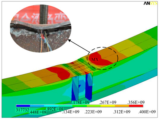
FIGURE 9. Equivalent stress distribution at yield loading of the bottom flange plate (unit: Pa).
As can be seen from Table 2, the finite element calculation result of the cracking load of concrete slabs is basically consistent with the test value, accounting for about 6.5% of the ultimate load. After reaching the cracking load of concrete, the ANSYS program will record the cracking situation of SOLID65 in each loading step and represent the cracking and fracturing behavior with circles and octagons, respectively. Figure 10 shows the crack propagation of a half-span concrete slab under different load grades. As can be seen from the figure, the initial cracks occur near the mid-span of the concrete slab, and then gradually propagate to the beam end with the increase of load grade. When the load reaches about 40% Fu, all transverse cracks appear basically, and several inclined cracks occurred near the support position which is consistent with the phenomenon observed in the test process.
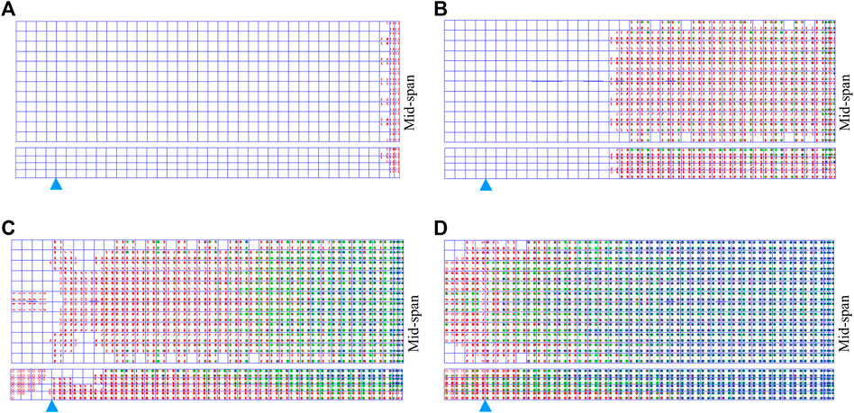
FIGURE 10. Simulation of crack propagation of the concrete slab under different load levels: (A) load to the Fcr; (B) load to the 25% Fu; (C) load to the 40% Fu; and (D) load to the Fu.
The FEA model of the test beam is developed as mentioned previously, and the comparison and verification between calculation results and test data are carried out. Based on the FEA model, the parametric study on the bearing capacity in negative moment regions of composite beams strengthened with CFRP laminates is conducted in this section. The parameters considered include CFRP layout width, layout position, layer number, longitudinal reinforcement ratio, and shear connection degree.
To analyze the influence of the CFRP layout width on the mechanical properties of composite beams in negative moment regions, the layout width of CFRP laminates in the FEA model is equivalent to 100, 200, 300, 400, 500, and 600 mm respectively, under the premise of keeping the structural size of composite beams unchanged, as shown in Figure 11. Table 3 shows the cracking load, reinforcement yield load, and ultimate load of composite beams with different widths of CFRP laminates. The reinforcement ratio is chosen as 4.0% and 0.5%. It can be seen from the table that the mechanical properties of composite beams under negative moments with CFRP laminates are improved to a certain extent, especially when the reinforcement ratio is low. It is mainly manifested in the following aspects: the CFRP laminates can improve the crack resistance of the concrete slab in the negative moment region of composite beams, and the cracking load can be increased by about 5.0%; when the reinforcement ratio is high, the load at the yield stage of the reinforcing bar in the concrete slab with CFRP laminates is increased by less than 5% compared with the composite beam without CFRP laminates, and the growth rate reaches to 18.6% under a low reinforcement ratio; when the reinforcement ratio is high, the ultimate load of the composite beam with CFRP laminates is increased within 12% compared with the beam without CFRP, and the growth rate tends to be stable when the layout width exceeds 300 mm (Figure 12A); however, the growth rate at a low reinforcement ratio can reach up to 25.2%, and the ultimate load increases linearly with the increase of the layout width (Figure 12B).
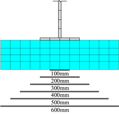
FIGURE 11. Arrangement of the CFRP with different widths.
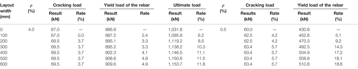
TABLE 3. Calculated values by the FEA with different widths of the CFRP.
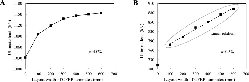
FIGURE 12. Curve of the ultimate load varied with CFRP width: (A) reinforcement ratio ρ = 4.0%; (B) reinforcement ratio ρ = 0.5%.
When the concrete slab in the negative moment region of the composite beam is not bonded with CFRP laminates within the full width, an FEA model considering the layout position (Figure 13) is carried out to analyze the impact on the bearing performance of composite beams. In the FEA model, the total width of the CFRP layout is designed as 300 mm, and the reinforcement ratio of longitudinal reinforcement in the concrete slab is designed as 0.5%. The calculation results show that the load-deflection curves of the composite beams with the different layout positions of CFRP laminates coincide well, as shown in Figure 14A. When the total layout width of the CFRP laminates remains unchanged, the different layout positions have little effect on the bearing performance of the composite beam, with a cracking load, reinforcement yield load, and ultimate load of about 63, 490, and 830 kN, respectively. Figure 14B shows the curves of the maximum tensile stress of CFRP laminates varied with load. It can be seen that the maximum tensile stress of the CFRP laminates in the three layouts is basically the same before concrete cracking. However, the maximum tensile stress of the CFRP laminates arranged in three columns is smaller than that of the other two forms after the crack appears. Therefore, to reduce the stress of the CFRP laminates and control the crack width at the edge of the concrete slab, the CFRP laminates should be reasonably distributed along the width of the concrete slab in practical applications.

FIGURE 13. Arrangement of the CFRP with different positions.
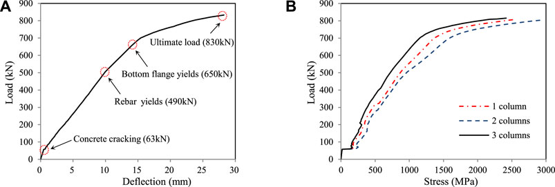
FIGURE 14. Variation curves of deflection and CFRP stress: (A) load-deflection curve; (B) load-maximum tensile stress of the CFRP curve.
In practical engineering, the load-bearing performance of the structure is often guaranteed by increasing the number of CFRP adhesive layers. But this method tends to be conservative, resulting in a waste of materials. To study the influence of the layer number of CFRP laminates on the mechanical properties of composite beams under the action of negative moments, the numerical modeling and calculation analysis of composite beams with 1–5 layers of CFRP laminates on concrete slabs were carried out. The width of CFRP laminates is designed as 600 mm and it is arranged in three columns. Table 4 shows the cracking load, reinforcement yield load and ultimate load of composite beams with different layer numbers of CFRP laminates. The reinforcement ratio is chosen as 4.0% and 0.5%. It can be seen from the table that the cracking load of the concrete slab bonded with CFRP laminates can be increased by about 5.0%. But with the increase in the layer number, there is no significant improvement. When the reinforcement ratio is high, the load at the yield stage of the reinforcing bar in the concrete slab bonded with CFRP laminates is increased by less than 10% compared with the composite beam without CFRP laminates. However, the load-bearing performance of composite beams with more bonded layers is not significantly improved on the whole (Figure 15A). When the reinforcement ratio is low, the bearing performance of the composite beam with 1 ∼ 3 layers of CFRP laminates is greatly improved. The yield load of the reinforcing bar is increased by 26.5% and the ultimate load is increased by 30.3% when three layers of CFRP laminates are arranged. However, with the further increase in the number of adhesive layers, the load-bearing performance is not significantly improved (Figure 15B). In practical engineering, a reasonable number of layers should be arranged in combination with design requirements and theoretical calculations.
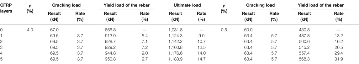
TABLE 4. Calculated values by the FEA with different layers of CFRP.
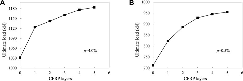
FIGURE 15. Curve of the ultimate load of the composite beam varied with CFRP layers: (A) reinforcement ratio ρ = 4.0%; (B) reinforcement ratio ρ = 0.5%.
To study the influence of the longitudinal reinforcement ratio on the bearing capacity in negative moment regions of composite beams, the FEA model is developed with reinforcement ratios of 0.5%, 1.5%, 2.5%, 3.5%, and 4.5%, under the condition of keeping the structure and size of the composite beams unchanged. The layer number of CFRP laminates is designed as 1. The width of CFRP laminates is designed as 600 mm, and the layers are arranged in three columns. The curves of the ultimate bearing capacity of composite beams under negative moments with/without CFRP laminates varied with the reinforcement ratio are given in Figure 16. It can be seen from the figure that the longitudinal reinforcement ratio has a great influence on the bearing performance in the negative moment region of the composite beam. The ultimate load increases with the increase in the reinforcement ratio, and the growth rate reaches 15% ∼ 45%. Compared with the composite beam without CFRP laminates, the ultimate load of the composite beam bonded with CFRP laminates is increased by 10% ∼ 15%.
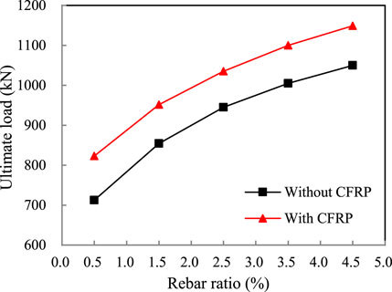
FIGURE 16. Curve of the ultimate load varied with the longitudinal rebar ratio.
To study the effect of the shear connection degree on the bearing performance in negative moment regions of composite beams, the FEA model is developed with shear connection degrees of 40%, 60%, 80%, 100%, and 100%, under the condition of keeping the structure and size of composite beams unchanged. The longitudinal reinforcement ratio, the width of CFRP laminates, the layer number, and the column number of CFRP laminates are designed as 0.5%, 600 mm, 1, and 3, respectively. The curves of the ultimate bearing capacity of composite beams under negative moments with/without CFRP laminates varied with shear connection degrees are given in Figure 17. During the whole loading process of the FEA, it is found that when the shear connection degree is more than 40%, the maximum slip at the composite beam interface does not exceed 0.2 mm, which is less than the ultimate slip value of the stud connection (Fan, 2003). That is, no shear failure of the connectors occurs during structural loading. It can be seen from the analysis in Figure 17 that the ultimate load of the composite beam bonded with CFRP laminates is increased by about 15% compared with the beam model without CFRP laminates under the same loading conditions. However, the shear connection degree has little effect on the bearing capacity of the composite beam under negative moments. When the shear connection degree is 100% and above, the bearing capacity of the composite beam bonded with CFRP laminates in the negative moment region increases by about 5%, while the growth rate of the ultimate load of composite beams without CFRP laminates is less than 3%. This phenomenon is consistent with the research results in the existing literature (Loh et al., 2004), that is, the ultimate bearing capacity of composite beams in the negative moment region does not significantly decrease when the shear connection degree is reduced from 100% to 33%. However, considering the factors such as the fatigue performance of the connector and the complex force in the negative moment region, it is still recommended to design the studs based on the relevant specification (BS EN 1994-2, 2005; BS 5950, 1990), that is, the degree of shear connection should not be less than 100%.
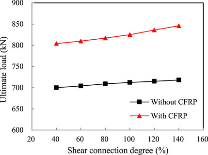
FIGURE 17. Curve of the ultimate load varied with the degree of shear connection.
In this study, the FEA model of composite beams under negative moments is developed with ANSYS software by selecting reasonable elements and material constitutive relations. The inelastic mechanical behavior of the test beam is simulated and calculated, and the accuracy of the FEA model is verified by the comparative analysis with the test results. Then the influence of CFRP laminates on the bearing performance of composite beams under negative moment is considered, and a parametric analysis is further carried out. The main conclusions are as follows:
(1) The FEA model can accurately predict the general mechanical behavior of steel-concrete composite beams under the action of negative moments. The finite element calculation results considering the interface slip effect are closer to the experimental values. The assumption of a perfect bond between reinforcement and the concrete and the neglect of the weakening effect of shear connectors in concrete slabs are the main reasons for the higher nonlinear stiffness of the FEA model than the experimental results.
(2) According to the analysis of the effect of the layout width of CFRP laminates, it is found that the bonded CFRP laminates can effectively improve the flexural performance of composite beams under negative moments. The crack resistance of the concrete slab bonding with CFRP laminates can be improved with the cracking load increasing by about 5.0%.
(3) From the analysis of the effect of the layout position of CFRP laminates, it can be seen that a different layout position has little influence on the load-bearing performance of composite beams, when the total width of CFRP laminates keeps unchanged. The maximum tensile stress of the CFRP laminates arranged by different layout methods remains almost unchanged before concrete cracking, while the maximum stress of CFRP laminates arranged in three columns is less than that of the other two forms after the crack appears.
(4) From the analysis of the influence of the layer number of CFRP laminates, it can be concluded that the load-bearing performance of the composite beams bonded with 1 ∼ 3 layers of CFRP laminates is greatly improved when a low reinforcement ratio is designed. But the bearing performance is not significantly improved with the further increase in the number of layers. Compared with the low reinforcement ratio, the number of bonded layers has no significant effect on improving the bearing performance of composite beams with the high reinforcement ratio.
(5) From the analysis of the effect of the longitudinal reinforcement ratio and shear connection degree, it is found that the longitudinal reinforcement ratio has a great influence on the bearing performance in the negative moment region of composite beams bonded with CFRP laminates, while the influence of shear connection degree is not significant. However, it is still suggested that the shear connection degree in the negative moment region of composite beams should not be less than 100% from the design point of view.
The original contributions presented in the study are included in the article/supplementary material; further inquiries can be directed to the corresponding authors.
AS conceived the work and wrote the manuscript. AS, HX, and QL developed the numerical model. AS and SW analyzed the results and revised the manuscript. All authors read and agreed to the published version of manuscript.
This research was sponsored by the school-level research project of Yancheng Institute of Technology (No. xjr2021007).
The authors declare that the research was conducted in the absence of any commercial or financial relationships that could be construed as a potential conflict of interest.
All claims expressed in this article are solely those of the authors and do not necessarily represent those of their affiliated organizations, or those of the publisher, the editors, and the reviewers. Any product that may be evaluated in this article, or claim that may be made by its manufacturer, is not guaranteed or endorsed by the publisher.
QL acknowledges the National Natural Science Foundation of China (No. 52108269), and the Scientific and Technology Research Program of Chongqing Municipal Education Commission (No. KJQN202100716).
BS 5950 (1990). Structural Use of Steel Work in Building, Part 3, Section 3.1: Code of Practice for Design of Composite Beams. London, England: British Standard Institution.
BS EN 1994-2 (2005). Eurocode 4: Design of Composite Steel and Concrete Structures, Part 2: General Rules and Rules for Bridges. Brussels, Belgium: European Committee for Standardization.
Chen, T., Gu, X., and Li, H. (2011). Behavior of Steel-Concrete Composite Cantilever Beams with Web Openings under Negative Moment. Int. J. Steel. Struct. 11 (1), 39–49. doi:10.1007/S13296-011-1004-8
Deng, J., Lee, M. M. K., and Li, S. (2011). Flexural Strength of Steel-Concrete Composite Beams Reinforced with a Prestressed CFRP Plate. Constr. and Build. Mater. 25, 379–384. doi:10.1016/j.conbuildmat.2010.06.015
El-Zohairy, A., Salim, H., Shaaban, H., Mustafa, S., and El-Shihy, A. (2017). Experimental and FE Parametric Study on Continuous Steel-Concrete Composite Beams Strengthened with CFRP Laminates. Constr. and Build. Mater. 157, 885–898. doi:10.1016/j.conbuildmat.2017.09.148
Fan, J. (2003). Experimental and Theoretical Research on Continuous Composite Steel-Concrete Beams. PhD thesis. Beijing, China: Tsinghua University.
Fan, J., Gou, S., Ding, R., Zhang, J., and Shi, Z. (2020). Experimental and Analytical Research on the Flexural Behaviour of Steel-ECC Composite Beams under Negative Bending Moments. Eng. Struct. 210, 110309. doi:10.1016/j.engstruct.2020.110309
GB 50010-2010 (2010). Code for Design of Concrete Structures. Beijing, China: Ministry of Construction of China.
Ghafoori, E., Motavalli, M., Nussbaumer, A., Herwig, A., Prinz, G. S., and Fontana, M. (2015). Determination of Minimum CFRP Pre-stress Levels for Fatigue Crack Prevention in Retrofitted Metallic Beams. Eng. Struct. 84 (10), 29–41. doi:10.1016/j.engstruct.2014.11.017
Hamoda, A., Hossain, K. M. A., Sennah, K., Shoukry, M., and Mahmoud, Z. (2017). Behaviour of Composite High Performance Concrete Slab on Steel I-Beams Subjected to Static Hogging Moment. Eng. Struct. 140, 51–65. doi:10.1016/j.engstruct.2017.02.030
Hawileh, R. A., Naser, M. Z., and Abdalla, J. A. (2013). Finite Element Simulation of Reinforced Concrete Beams Externally Strengthened with Short-Length CFRP Plates. Compos. Part B Eng. 45 (1), 1722–1730. doi:10.1016/j.compositesb.2012.09.032
Hawileh, R. A., Rasheed, H. A., Abdalla, J. A., and Al-Tamimi, A. K. (2014). Behavior of Reinforced Concrete Beams Strengthened with Externally Bonded Hybrid Fiber Reinforced Polymer Systems. Mater. Des. 53, 972–982. doi:10.1016/j.matdes.2013.07.087
Hognestad, E. (1951). A Study of Combined Bending and Axial Load in Reinforced Concrete Members. Bull. Ser. Urbana-Champaign, Am. Univ. Ill. Eng. Exp. Stn. 399.
Karam, E. C., Hawileh, R. A., El Maaddawy, T., and Abdalla, J. A. (2017). Experimental Investigations of Repair of Pre-damaged Steel-Concrete Composite Beams Using CFRP Laminates and Mechanical Anchors. Thin-Walled Struct. 112, 107–117. doi:10.1016/j.tws.2016.12.024
Keykha, A. H. (2019). Behavior of Defective Curved Steel Beams Strengthened by a CFRP Composite. Mech. Compos. Mat. 55 (6), 525–534. doi:10.1007/s11029-019-09831-y
Lin, J., Lin, L., Peng, Z., Xu, R., and Wang, G. (2022). Cracking Performance in the Hogging-Moment Regions of Natural Curing Steel-Uhpc and Steel-Uhtcc Continuous Composite Beams. J. Bridge. Eng. 27 (2), 04021106. doi:10.1061/(ASCE)BE.1943-5592.0001820
Lin, W., and Yoda, T. (2014). Numerical Study on Horizontally Curved Steel-Concrete Composite Beams Subjected to Hogging Moment. Int. J. Steel. Struct. 14 (3), 557–569. doi:10.1007/s13296-014-3013-x
Loh, H. Y., Uy, B., and Bradford, M. A. (2004). The Effects of Partial Shear Connection in the Hogging Moment Regions of Composite Beams Part II-Analytical Study. J. Constr. Steel Res. 60 (6), 921–962. doi:10.1016/j.jcsr.2003.10.008
Nguyen, Q. H., Hjiaj, M., Uy, B., and Guezouli, S. (2009). Analysis of Composite Beams in the Hogging Moment Regions Using a Mixed Finite Element Formulation. J. Constr. Steel Res. 65 (3), 737–748. doi:10.1016/j.jcsr.2008.07.026
Nie, J., Fan, J., and Cai, C. S. (2004). Stiffness and Deflection of Steel-Concrete Composite Beams under Negative Bending. J. Struct. Eng. 130 (11), 1842–1851. doi:10.1061/(ASCE)0733-9445(2004)130:11(1842)
Ollgaard, J., Slutter, R., and Fisher, J. (1971). Shear Strength of Stud Connectors in Lightweight and Normal Concrete. AISC Eng. J. 8 (2), 55–64.
Qin, F., Zhang, Z., Yin, Z., Di, J., Xu, L., and Xu, X. (2020). Use of High Strength, High Ductility Engineered Cementitious Composites (ECC) to Enhance the Flexural Performance of Reinforced Concrete Beams. J. Build. Eng. 32, 101746. doi:10.1016/j.jobe.2020.101746
Song, A., Wan, S., Jiang, Z., and Xu, J. (2018). Residual Deflection Analysis in Negative Moment Regions of Steel-Concrete Composite Beams under Fatigue Loading. Constr. and Build. Mater. 158, 50–60. doi:10.1016/j.conbuildmat.2017.09.075
Sweedan, A. M. I., Alhadid, M. M. A., and El-Sawy, K. M. (2016). Experimental Study of the Flexural Response of Steel Beams Strengthened with Anchored Hybrid Composites. Thin-Walled Struct. 99, 1–11. doi:10.1016/j.tws.2015.10.026
Tavakkolizadeh, M., and Saadatmanesh, H. (2003). Strengthening of Steel-Concrete Composite Girders Using Carbon Fiber Reinforced Polymers Sheets. J. Struct. Eng. 129 (1), 30–40. doi:10.1061/(ASCE)0733-9445(2003)129:1(30)
Teng, J. G., Fernando, D., and Yu, T. (2015). Finite Element Modelling of Debonding Failures in Steel Beams Flexurally Strengthened with CFRP Laminates. Eng. Struct. 86, 213–224. doi:10.1016/j.engstruct.2015.01.003
Wang, B., Huang, Q., and Liu, X. (2017). Deterioration in Strength of Studs Based on Two-Parameter Fatigue Failure Criterion. Steel Compos. Struct. 23 (2), 239–250. doi:10.12989/scs.2017.23.2.239
Wang, W., Zhang, X.-d., Zhou, X.-l., Wu, L., and Zhu, H.-j. (2021). Study on Shear Behavior of Multi-Bolt Connectors for Prefabricated Steel-Concrete Composite Beams. Front. Mat. 8, 625425. doi:10.3389/fmats.2021.625425
Zhang, Z., Liu, D., Ding, Y., and Wang, S. (2022). Mechanical Performance of Strain-Hardening Cementitious Composites (SHCC) with Bacterial Addition. J. Infrastruct. Preserv. Resil. 3 (3). doi:10.1186/s43065-022-00048-3
Keywords: steel-concrete composite beam, negative moment, CFRP laminates, finite element, parametric analysis
Citation: Song A, Xu H, Luo Q and Wan S (2022) Finite Element Analysis on Inelastic Mechanical Behavior of Composite Beams Strengthened With Carbon-Fiber-Reinforced Polymer Laminates Under Negative Moment. Front. Mater. 9:859663. doi: 10.3389/fmats.2022.859663
Received: 21 January 2022; Accepted: 25 April 2022;
Published: 31 May 2022.
Edited by:
Zhigang Zhang, Chongqing University, ChinaCopyright © 2022 Song, Xu, Luo and Wan. This is an open-access article distributed under the terms of the Creative Commons Attribution License (CC BY). The use, distribution or reproduction in other forums is permitted, provided the original author(s) and the copyright owner(s) are credited and that the original publication in this journal is cited, in accordance with accepted academic practice. No use, distribution or reproduction is permitted which does not comply with these terms.
*Correspondence: Hongtao Xu, eGh0MTk3OEBoZWJ1c3QuZWR1LmNu; Shui Wan, c2V1ZnJwYnJpZGdlQDE2My5jb20=
Disclaimer: All claims expressed in this article are solely those of the authors and do not necessarily represent those of their affiliated organizations, or those of the publisher, the editors and the reviewers. Any product that may be evaluated in this article or claim that may be made by its manufacturer is not guaranteed or endorsed by the publisher.
Research integrity at Frontiers
Learn more about the work of our research integrity team to safeguard the quality of each article we publish.