 Hongbo Peng
 Zhongya Zhang1,2
 Yang Zou
94% of researchers rate our articles as excellent or good
Learn more about the work of our research integrity team to safeguard the quality of each article we publish.
Find out more
ORIGINAL RESEARCH article
Front. Mater., 07 April 2022
Sec. Structural Materials
Volume 9 - 2022 | https://doi.org/10.3389/fmats.2022.859532
This article is part of the Research TopicAdvanced Concretes and Their Structural ApplicationsView all 23 articles
The assembly construction of prefabricated UHPC elements can well balance quality reliability and construction convenience, thus it has excellent application prospects in bridge engineering. The joints between prefabricated elements are the key to ensuring the overall force performance of the structure, which directly determine the load-bearing capacity and the life of structure. To clarify the bending behavior of epoxy adhesive joints between prefabricated UHPC elements, four groups of 12 bending tests were carried out with different interface treatment forms as parameters. The failure modes, load-deflection curves, and ultimate bending strength of the interface were investigated. The results reveal that the interfacial failure modes mainly include the interfacial stripping failure of epoxy-UHPC surface, steel fibers and fine aggregates into UHPC surface by pulling out, and tensile damage of UHPC at the root of key teeth on the side of the keyway interface. The load-deflection curves of all specimens exhibit the two-fold lines form. The load tends to rise linearly during the loading phase, and there is no yielding phase before the failure. The load-carrying capacity of the specimen is lost immediately after the failure, and no reliable residual strength is available except for the keyway interface. In addition, the bending strength of rough interface, groove interface, and keyway interface are respectively improved by −24.02, 2.34, and 4.64%, compared with the natural interface. So it is recommended that the joint between prefabricated UHPC elements take the form of keyway interface. Finally, a simplified force model of the keytooth adhesive joint is proposed, and a calculation formula for the flexural bearing capacity is established based on the principal of Mohr’s circle, based on the experimental results and theoretical analysis. The mean ratio of the proposed adhesive joint calculation equation to the experimental results was 0.925 with a standard deviation of 0.065.
Normal concrete has been widely used because of its advantages of easy material extraction, good moldability and high compressive strength, but it also has the disadvantages of low tensile strength, difficult to control the crack width after cracking and obvious brittle characteristics. To improve the brittle properties of normal concrete and limit its crack development, a large majority of scholars and researchers at home and abroad have developed high performance fiber reinforced concrete, represented by ultra-high performance concrete (UHPC) and engineered cementitious concrete (ECC). ECC has the obvious strain-hardening characteristics, high tensile and compressive toughness, excellent durability, good deformation capacity and energy dissipation capacity. The application of this material in buildings, bridges and other structures can meet the safety, applicability and durability requirements. Qin et al. (Qin et al., 2020) applied high strength, high ductility ECC to strengthen reinforced concrete beams and investigated its flexural properties. The test results show that when the beam reaches its ultimate state, no local cracking occurs in tensile zone, but more micro-cracks appear due to the high toughness of ECC. In addition, the cracking load, yield load, ultimate load, ductility and energy absorption capacity are improved. Zhang et al. (Zhang et al., 2020; Zhang et al., 2021) developed the high strength, high ductility ECC with substitution of fly ash and cement by rice husk ash to enrich the variety of ingredients in ECC and make ECC more eco-friendly. In addition, to realize self-healing and increase the strength of ECC, Zhang et al. (Zhang et al., 2022) investigated the mechanical properties of ECC with the addition of vegetative bacterial cells. The results show that the compressive, cracking and tensile strength of ECC are increased, but the tensile strain capacity is slightly decreased due to the addition of bacteria.
UHPC is a fiber-reinforced cementitious composite material with a compressive strength of 150 MPa or more and excellent mechanical properties, durability, and toughness (De Larrard and Sedran, 1994; Wille et al., 2011; Wang et al., 2015; Xue et al., 2020; Du et al., 2021). The steel fibers into UHPC inhibit the sprouting and development of cracks, thereby enhancing their tensile properties (Liew, 2015; Lee et al., 2017; Meng and Khayat, 2017). In addition, the dense matrix microstructure provides high resistance to the intrusion of harmful chemical ions (
However, UHPC has a risk of early cracking due to internal self-drying and chemical shrinkage during the setting and hardening process, which can cause self-shrinkage and is usually greater than 800
In the prefabricated UHPC assembly structure, the joints can make it have better force transmission performance and ensure its impermeability and integrity. At present, the joints can be divided into three types according to the connection material at the joints: the dry joints with direct contact on the surface of the joints, the wet joints with filled concrete or mortar, and the glued joints with epoxy resin. Dry joints are banned by the AASHTO due to the disadvantages of not providing effective durability protection for post-tensioned prestressing tendons, and it is suggested that only glue joints or wet joints can be used in all precast assembled concrete structures. Pan et al. (Pan et al., 2016) compared the flexural performance of five novel wet joints of steel-RPC composite deck slabs. Since steel fibers improve the performance of the RPC layer after cracking, a durability-based RPC tensile stress is recommended to replace the initial cracking stress for a more economical deck panel design. Shao et al. (Shao et al., 2013; Shao et al., 2017) demonstrated that the crack-resistance performance of steel-plate enhanced wet joints and reinforcement-enhanced wet joints was better than conventional wet joints by bending tests on steel-RPC composite deck slabs. Xiao et al. (Xiao et al., 2022) conducted a study on the flexural performance of dovetail wet joints and rectangular wet joints in steel-UHPC composite deck slabs under hogging moment. Chen at al. (Chen et al., 2018) proposed novel interfacial treatments such as epoxy resin treatment and high-pressure water jet chiseling for the wet joints of steel-UHPC composite decks and carried out experiments to study the force mechanism of wet joints. It is recommended that the interfacial treatment using a high-pressure water jet to chisel away the fine aggregate can be used When the construction conditions are suitable. Zhao et al. (Zhao et al., 2018) conducted a full-scale test and finite element simulation study on the flexural performance of dovetail wet joints in steel-RPC composite deck slabs under hogging moment. The test results showed that: reinforcement rate is a key factor affecting crack development and load-deflection curve, and a reinforcement rate of 4.5% is recommended for a 55 mm-thick RPC layer. Lee et al. (Lee et al., 2011) investigated the shear performance and ultimate strength of cast-in-place joints and epoxy adhesive joints in prefabricated UHPC segmental bridges, considering the test parameters such as joint type, load-displacement relationship, fracture behavior, and fracture mode.
However, for the long-span bridges, wet joints are difficult to ensure the quality of joints due to the complex construction process. If the UHPC wet joints are not maintained properly, its mechanical performance will be affected greatly. Epoxy joints have the advantages of good integral performance, better shear bearing capacity than wet joints and lower requirements for maintenance conditions, etc., and have a wider range of adaptation. But the flexural performance of epoxy adhesive joints has been studied quite rarely. Therefore, in this study, four groups of 12 epoxy adhesive prefabricated UHPC bending specimens with different interfacial treatments at their joints were designed to study the bending performance. In addition, a simplified mechanical model of the key-tooth adhesive joint was proposed and a calculation formula for the flexural bearing capacity was established based on the experimental results and theoretical analysis. The research results provide a reference for the study and engineering applications of epoxy adhesive joints of prefabricated UHPC elements.
The main components of UHPC used in this test include cement, silica fume, quartz sand, quartz powder, and straight steel fibers, and the matrix compound is shown in Table 1. The straight steel fiber has a volume ratio of 2%, a length of 8 mm, a diameter of 0.12 mm, and a nominal tensile strength of 2,700 MPa.
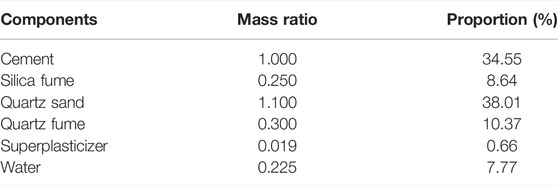
TABLE 1. Mix ratio of UHPC.
The mechanical properties of the UHPC material used in this test are listed in Table 2. Among them, the mechanical properties of UHPC were obtained by three 100 mm × 100 mm × 100 mm cubes, three 100 mm × 100 mm × 400 mm bending specimens, three 100 mm × 100 mm × 300 mm prisms, and three dogbone-shaped tensile specimens.

TABLE 2. Mechanical properties of materials.
The epoxy resin is CBSR-A/B, which contains the main agent CBSR-A and curing agent CBSR-B, with a ratio of 2:1. According to The methods for properties of resin casting body (GB/T 2567-2021), the mechanical properties of epoxy resin were obtained by tensile and compression tests, as shown in Figure 1. The tensile strength, compressive strength, and flexural strength of the epoxy resin are 30 MPa, 100 MPa, and 45 MPa, respectively, and the tensile modulus of elasticity is 3200 MPa.
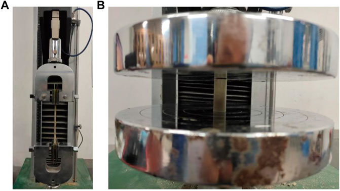
FIGURE 1. Mechanical properties tests of epoxy resin. (A) Tensile test. (B) Compression test.
A total of 12 epoxy-adhesive UHPC-UHPC specimens in four groups were designed for this experiment. As shown in Figure 2, each specimen consists of two prefabricated UHPC bonded by epoxy resin. The dimension of the single UHPC are 249 mm × 100 mm × 100 mm, and the thickness of the epoxy layer is 2 mm (Zou et al., 2021). The surface at the interface of the two precast UHPC needs to be treated, which can be divided into four types of interfaces according to different treatments: 1) Natural interface, which is a smooth interface made by natural pouring; 2) Rough interface, where the UHPC surface is polished to expose the steel fibers; 3) Groove interface, where four grooves are evenly arranged on the interface, with a single groove size of 2 mm × 10 mm × 100 mm and a groove spacing of 10 mm. 4) Keyway interface. Two keyways were arranged on one side of the prefabricated UHPC interface, the width of the keyway root is 20 mm, the depth is 10 mm, and the spacing of the keyway centerline is 40 mm. The specimens were grouped as listed in Table 3.
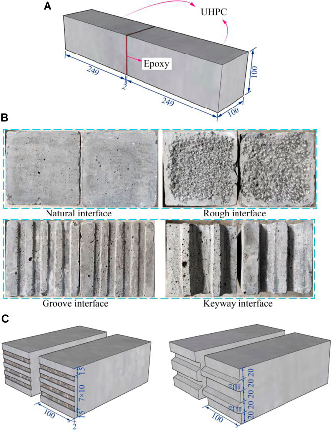
FIGURE 2. Geometry of the specimen(Unit: mm). (A) 3D views. (B) Interface type. (C) Dimension details.
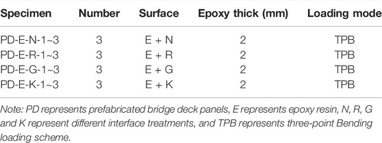
TABLE 3. Details of specimens.
As shown in Figure 3, the specimens were fabricated in sequential steps as follows:
(1) Making the formwork based on the designed specimen size;
(2) Pouring the UHPC;
(3) The specimens were demolded after resting for 3 days in a room with the temperature of 20 ± 5°C and relative humidity greater than 50%, and the demolded specimens were steam cured for 48 h to ensure that the UHPC reached the design strength;
(4) The mechanical chiseling of the interface of PD-E-R group specimens until the steel fibers are exposed;
(5) Applying a 2-mm-thick epoxy resin layer uniformly at the interface of each group specimen and applying normal pressure to form the whole combined UHPC-UHPC specimen;
(6) Curing all specimens naturally for 7 days to ensure that the epoxy adhesive reaches its design bond strength.
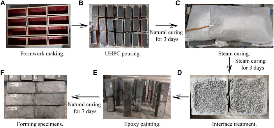
FIGURE 3. The production process of the specimen. (A) Formwork making. (B) UHPC pouring. (C) Steam curing. (D) Interface treatment. (E) Forming specimens. (F) Epoxy painting.
The loading device is shown in Figure 4. The test was carried out using the MTS universal material testing machine with a capacity of 200 kN, and all specimens were loaded by the three-point bending test with a displacement-controlled loading rate of 0.1 mm/min.
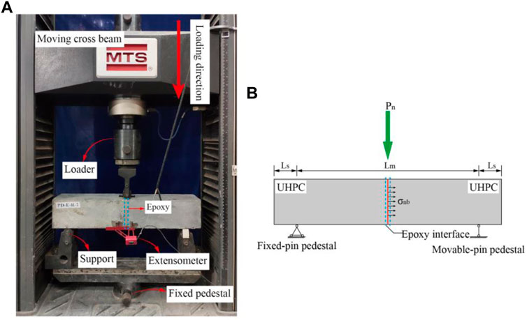
FIGURE 4. Experimental setup. (A) Loading device diagram. (B) Force mode.
The main test items are as follows: 1) Load-deflection curve; 2) Interfacial bending strength; and 3) Final failure modes of the specimen. The load-deflection curve is obtained by the data acquisition system of the MTS universal material testing machine. The interfacial bending strength is calculated by Eq. 2.1. The final failure modes of the specimen are observed and recorded at the end of loading.
where
The two parts of UHPC of each specimen were separated at the end of the test to observe the failure modes at the interface. The failure modes of the interface for a representative specimen of each group are shown in Figure 5.
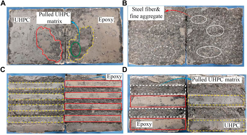
FIGURE 5. Failure mode of specimen. (A) PD-E-N. (B) PD-E-R. (C) PD-E-G. (D) PD-E-K.
As shown in Figure 5A, the interfacial failure modes of PD-E-N series specimens are mainly divided into two parts: the stripping between the epoxy layer-UHPC interface and the damage of the UHPC surface layer. The area outside the red and yellow circles in Figure 5A mainly shows the peeling between the epoxy layer-UHPC interface. Both the epoxy layer and UHPC surface are smooth, and no signs of damage are found, indicating that neither is broken by tension. In addition, the area inside the red and yellow circles mainly shows the damage of the UHPC surface layer with a thickness of about 1 mm. The pulled UHPC matrix can be observed on the epoxy surface, which indicates that the bonding performance of the epoxy and UHPC is better, thus leading to the damage of the UHPC surface layer under the tensile stress.
As shown in Figure 5B, the interfacial failure modes of PD-E-R series specimens mainly show the pull-out of the UHPC layer on one side of the interface, while the epoxy layer is intact on the other side. The steel fibers and fine aggregates pulled out of UHPC can be observed in the white circle area in Figure 5B, this is because some of the exposed steel fibers and fine aggregates are embedded in the epoxy layer, so its bonding performance with the epoxy layer is better. However, the mechanical chiseling treatment of the UHPC surface leads to the damage and loosening of the surface UHPC layer, which causes the interfacial normal tensile strength to be controlled by the loosened UHPC layer.
As shown in Figure 5C, the interfacial failure modes of PD-E-G series specimens are similar to that of PD-E-N, which mainly shows the stripping between the epoxy layer-UHPC interface inside the grooves and the damage of the UHPC surface layer outside the grooves. The epoxy layer and UHPC surface inside the grooves are smooth without damage signs, and they show stripping of the interface and lose the bearing capacity under the normal tension. Compared with the epoxy layer inside the grooves, the thickness of the epoxy layer in the interface area outside the grooves is thinner. Its bonding performance with the UHPC surface is better, leading to the UHPC surface layer being damaged under normal tension.
As shown in Figure 5D, the interfacial failure modes of PD-E-K series specimens mainly show that the UHPC at the root of key teeth on one side is pulled and the interfacial stripping between the epoxy-UHPC surface layer in the area outside the keyway. This indicates that the bonding performance of bonded UHPC-epoxy adhesive interface is excellent after the keyway treatment, and the tensile strength of the interface is controlled by the UHPC near the root of key teeth under normal tension. In addition, after the specimen reaches the ultimate bearing capacity and is damaged, the steel fibers into UHPC limit the development of cracks. The UHPC matrix on both sides of the cracks is not completely separated. The specimen can still bear a certain load and have residual strength.
The test results of this study are summarized in Table 4 and include the ultimate bearing capacity
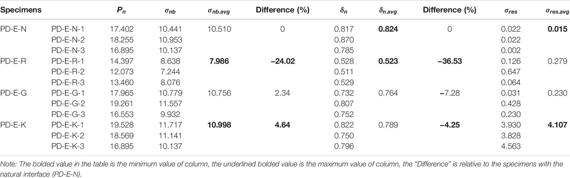
TABLE 4. The main results of the tests.
To compare the bending resistance of the various interfaces more intuitively way, a comparison of the bending performance of four different interfaces based on Table 4 is shown in Figure 6.
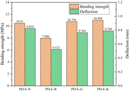
FIGURE 6. Interfacial parameters comparison.
As shown in Figure 6 and Table 4, in descending order of bending strength: the keyway interface, groove interface, natural boundary surface, and rough interface. Compared with the natural interface, the bending tensile strength of rough interface, groove interface, and keyway interface were increased by −24.02, 2.34, and 4.64%, respectively. The bending tensile strength of the rough interface is the lowest among all the treatment methods, because the mechanical chiseling destroys part of the matrix on the UHPC surface. And the looser UHPC layer makes the interface fail under the normal tensile force, and its strength is reduced significantly. Compared with the natural interface, the keyway interface has a more significant increase in bending strength because its failure modes are mainly the tensile damage of UHPC at the root of key teeth. In addition, the deflection at ultimate bending strength is less than 0.83 mm for all four interfaces. The rough interface, groove interface, and keyway interface were reduced by 36.53, 7.28, and 4.25%, respectively, compared to the natural surface. The deflection was also significantly reduced for the rough interface due to its significantly reduced load-carrying capacity.
Furthermore, the natural interface loses its bearing capacity immediately after the failure and has almost no residual strength. Although the rough and groove interfaces have improved compared with the natural surface, their residual strengths are still relatively low, only 0.279 and 0.23 MPa, respectively. However, the keyway interface has a residual strength of 4.107 MPa. It is the only interface with reliable residual strength among the four interfaces. This is because under the action of normal tension, although the UHPC at the root of the keyway is pulled, the presence of steel fibers limits the rapid development of crack so that the UHPC matrix on both sides of the damaged surface can still bear a certain amount of normal tension under the “connection” of steel fibers, that is, the tensile strength of UHPC after cracking constitutes the residual strength of the specimen.
In this study, the load applied to the specimens and the values of mid-span deflection of the specimens were obtained by the sensor acquisition system of the MTS universal material testing machine. The load-deflection curves of four groups of specimens are shown in Figure 7.
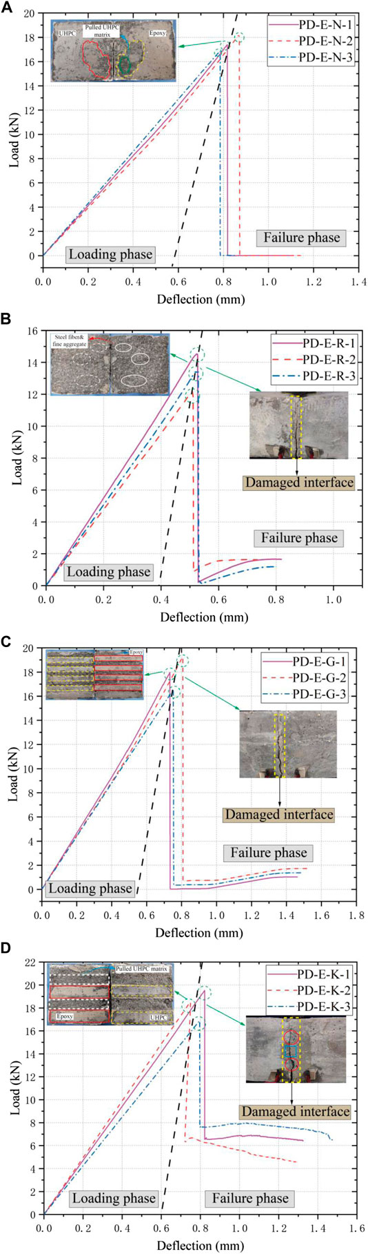
FIGURE 7. Load-deflection curves of all specimens. (A) PD-E-N specimens. (B) PD-E-R specimens. (C) PD-E-G specimens. (D) PD-E-K specimens.
As shown in Figure 7A, the load-deflection curves of PD-E-N series specimens exhibit two-fold line form, which is mainly divided into the loading and failure phases. The load rises steadily and almost linearly before the specimen reaches the ultimate load in the loading phase. The curves still maintain high linearity without an obvious yielding phase when the ultimate bearing capacity is near, which indicates that it does not have ductility. The specimens lose the load-bearing capacity immediately after reaching the ultimate load, without residual strength. This indicates that the interfacial failure belongs to brittle failure, consistent with the failure modes of epoxy layer-UHPC interfacial stripping.
As shown in Figures 7B–D, the general trend of load-deflection curves of the rough interface, groove interface, and keyway interface remains the same as that of the natural interface specimens, all of which mainly show two-fold line form. However, in contrast to the natural surface, the rough and groove interfaces have a certain residual strength after failure. The load shows a slightly increasing trend with the increment of deflection. For the keyway interface, the residual strength is significantly higher than that of the remaining three types of specimens, and the load decreases more slowly with the increment of deflection. This is due to the fact that under the action of normal tension, although the UHPC at the root of the keyway is pulled, the presence of steel fibers limits the rapid development of crack so that the UHPC matrix can still bear a certain amount of normal tension under the “connection” of steel fibers. In conclusion, the ultimate bending tensile strength and residual strength after the failure of the keyway interface are the highest among the four interface forms. The bending performance of the prefabricated UHPC-epoxy adhesive joints is the best when this interface form is adopted.
The stress state of epoxy adhesive joint is bending-shear composite stress under three-point bending load. Since the tensile strength of epoxy resin is greater than that of UHPC, the bending-shear failure of prefabricated UHPC elements is controlled by the tensile strength of UHPC. The cracks will appear on the UHPC next to the adhesive joint. The calculation diagram is shown in Figure 8.
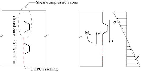
FIGURE 8. Calculation diagram of epoxy adhesive joint.
Since the initial damage and damage area of epoxy resin layer are difficult to define, the following basic assumptions are proposed according to the experimental phenomena to simplify the mechanical behavior of epoxy adhesive joints.
(1) The joint surface does not crack before reaching the ultimate state, and only the lower half of the adhesive layer cracks after reaching the ultimate state, so the cross-section area of the lower half is only considered when calculating the bearing capacity.
(2) The adhesive layer loses its bearing capacity after cracking immediately. The residual strength of the specimen is only provided by the bonding force of the upper adhesive layer and UHPC at the root of the key tooth.
(3) Ignoring the contribution of adhesive layer in key tooth region of cracking zone.
(4) The dimension of rectangular section is small, so the shear stress on the section is assumed to be uniformly distributed.
Based on the above basic assumptions and the experimental results of this study, the bearing capacity of the adhesive joint is provided by the bonding force of adhesive layer and UHPC at the root of the key tooth, as shown in Eq. 4.1. The contribution of the adhesive layer can be expressed as follows: Shear slip and normal separation occurred on the joint surface, and the bond strength of the adhesive layer provided resistance load. The adhesive layer begins to damage after the joint surface reaches the maximum bonding strength, and the adhesive layer quits immediately after cracking. It is worth noting that the adhesive layer cracking was observed only in the lower of the specimen, and no cracks were observed in the shear-compression zone under high stress. The failure mode of the key tooth is that the root of key tooth is pulled out under the bending-shear combined action. The adhesive layer of the key tooth region is not cracked, so it can be considered that the contribution of the key tooth is only provided by the key tooth matrix itself.
where
where
For the key teeth, most of the existing study are based on the major principal tensile stress theory (Gopal et al., 2020). The analysis of micro-element of UHPC near the root of the key tooth is shown in Figure 9. From the principle of Mohr’s circle, the major principal tensile stress can be obtained as Eq. 4.3:
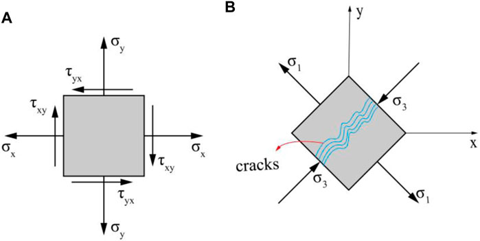
FIGURE 9. Stress state of the key tooth. (A) Stresses in given coordinate. (B) Principal stresses (Failure criteria).
Since the failure of key teeth is controlled by the tensile strength of UHPC,
where
In summary, for the smooth adhesive joints, the calculation formula can be expressed as Eq. 4.2 because its bearing capacity is only provided by the bonding force. For the key tooth adhesive joints, the bearing capacity can be expressed as Eq. 4.6.
As shown in Table 5, based on the calculation formulas of flexural capacity of epoxy adhesive joints proposed in this study, the smooth adhesive joints and key tooth adhesive joints are calculated, which are compared with the test results.
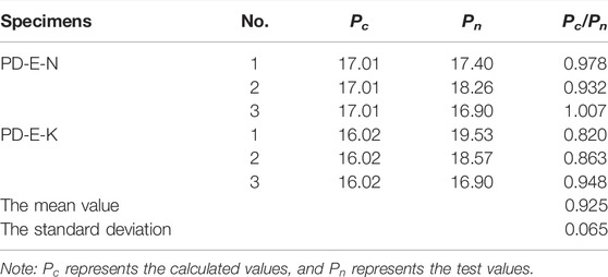
TABLE 5. Comparison between calculated and experimental values.
As can be seen from Table 5, the suggested formulas can better predict the bending capacity of smooth adhesive joints and key tooth adhesive joints. The ratio of calculated value to experimental value is 0.925, and the results are conservative. The standard deviation is 0.065, and the discreteness was small. However, the number of specimens is small in this study relatively, and for the key tooth adhesive joint, the parameters, such as the number and the geometric size of key teeth, are relatively simple. Therefore, the more applicable formula for calculating the bending capacity of key tooth adhesive joints remains to be further studied.
To clarify the bending performance of epoxy adhesive joints between prefabricated UHPC elements, the failure modes, load-deflection curves, and interfacial bond strength of prefabricated UHPC epoxy adhesive joints were studied through a three-point bending test. A calculation formula for the flexural bearing capacity was established based on the experimental results and theoretical analysis. The main conclusions are as follows:
(1) Under the action of normal bending tension, the failure modes of joints with different interface forms vary from each other. The smooth interface mainly shows interfacial stripping failure of the epoxy-UHPC surface layer. A minority of the UHPC surface layer is damaged due to the extraction of steel fibers and fine aggregate. The roughened interface shows interfacial failure due to the pull-out of steel fibers and fine aggregate embedded in epoxy. The groove interface mainly shows the stripping between the epoxy layer-UHPC interface inside the groove and the damage of the UHPC surface layer outside the groove. The keyway interface exhibits tensile damage of UHPC at the root of key teeth and the stripping of epoxy-UHPC surface layer interface in the area outside the keyway.
(2) The load-deflection curves of all specimens exhibit a two-fold line form, which has no yielding stage before reaching ultimate strength. The mid-span deflection values corresponding to the ultimate strength are lower than 0.83 mm. The interface is instantly damaged after reaching ultimate strength, without sufficient plastic deformation, and exhibits the characteristics of brittle damage.
(3) Compared with the natural surface, the bending tensile strength of rough interface, grooved interface, and keyway interface were improved by −24.02, 2.34, and 4.64%, respectively. Given that the mechanical chiseling method can damage the UHPC surface layer, which in turn reduces the bending strength of the interface, it is recommended to use high-pressure jet technology for the interface roughness treatment. For the keyway interface, which has the most reliable interfacial ultimate and residual strength values among the four groups of specimens, this interfacial form can be adopted for the joints of prefabricated UHPC elements.
(4) A simplified force model of the keytooth adhesive joint is proposed based on the experimental results and theoretical analysis, and a calculation formula for the flexural bearing capacity is established based on the principal of Mohr’s circle. The suggested formulas can better predict the bending capacity of smooth adhesive joints and key tooth adhesive joints. The ratio of calculated value to experimental value is 0.925, and the results are conservative. The standard deviation is 0.065, and the discreteness was small.
The original contributions presented in the study are included in the article/Supplementary Material, further inquiries can be directed to the corresponding author.
HP conceptualized the study, formulated the methodology, performed the software and formal analysis, and wrote and prepared the original draft. ZZ, YZ, and JG reviewed and edited the manuscript, supervised the study, was in charge of the project administration, and acquired the funding. XZh and XZe conducted data curation. All authors have read and agreed to the published version of the manuscript.
The authors express their sincere gratitude for the financial support provided by the National Natural Science Foundation of China (52008066), the Major Science and Technology Projects in Hainan (ZDKJ2021048), the China Postdoctoral Science Foundation (Grant No. 2021M693919) and Science and technology projects in TAR (XZ202001ZY0054G).
The authors declare that the research was conducted in the absence of any commercial or financial relationships that could be construed as a potential conflict of interest.
All claims expressed in this article are solely those of the authors and do not necessarily represent those of their affiliated organizations, or those of the publisher, the editors and the reviewers. Any product that may be evaluated in this article, or claim that may be made by its manufacturer, is not guaranteed or endorsed by the publisher.
Abdelbaset, H., Cheng, B., Tian, L., Li, H-T., and Zhang, Q-H. (2020). Reduce Hot Spot Stresses in Welded Connections of Orthotropic Steel Bridge Decks by Using UHPC Layer: Experimental and Numerical Investigation. Eng. Structures 220 (105708), 110988. doi:10.1016/j.engstruct.2020.110988
Abdelbaset, H., Cheng, B., Tian, L., Li, H.-T., and Zhao, J. (2022). Enhancing Fatigue Resistance of Rib-To-Floorbeam Welded Connections in Orthotropic Steel Bridge Decks by Using UHPC Layer: An Experimental Study. Structures 36, 153–167. doi:10.1016/j.istruc.2021.12.008
Chen, B. C., An, M. Z., Huang, Q. W., Wu, H. C., and Zhao, Q. (2016). “Application of Ultra-High Performance Concrete in Bridge Engineering in China,” in First International Interactive Symposium on UHPC, Iowa State University, Des Moines, IA, January 1, 2016 (Des Moines, Iowa, USA: Iowa State University). doi:10.21838/uhpc.2016.82
Chen, D., Zeng, M., Su, Q., and Lou, Y. (2018). Interfacial Treatment Measures of Wet Joints in Composite Bridge Deck Composed of Steel and UHPC Layer. China J. Highw. Transport 31, 154–162. doi:10.19721/j.cnki.1001-7372.2018.12.015
Cheng, Z., Zhang, Q., Bao, Y., Deng, P., Wei, C., and Li, M. (2021). Flexural Behavior of Corrugated Steel-UHPC Composite Bridge Decks. Eng. Structures 246, 113066. doi:10.1016/j.engstruct.2021.113066
De Larrard, F., and Sedran, T. (1994). Optimization of Ultra-High-Performance concrete by the Use of a Packing Model. Cement Concrete Res. 24, 997–1009. doi:10.1016/0008-8846(94)90022-1
Dieng, L., Marchand, P., Gomes, F., Tessier, C., and Toutlemonde, F. (2013). Use of UHPFRC Overlay to Reduce Stresses in Orthotropic Steel Decks. J. Constructional Steel Res. 89, 30–41. doi:10.1016/j.jcsr.2013.06.006
Du, J., Meng, W., Khayat, K. H., Bao, Y., Guo, P., Lyu, Z., et al. (2021). New Development of Ultra-High-Performance Concrete (UHPC). Composites B: Eng. 224, 109220. doi:10.1016/j.compositesb.2021.109220
Garas, V. Y., Kahn, L. F., and Kurtis, K. E. (2009). Short-Term Tensile Creep and Shrinkage of Ultra-High Performance Concrete. Cement and Concrete Composites 31, 147–152. doi:10.1016/j.cemconcomp.2009.01.002
Gopal, B., Hejazi, F., Hafezolghorani Esfahani, M., and Voo, Y. (2020). Shear Strength of Dry and Epoxy Joints for Ultra-High-Performance Fiber-Reinforced Concrete. ACI Struct. J. 117, 279–288. doi:10.14359/51718078
Haber, Z. B., Munoz, J. F., De la Varga, I., and Graybeal, B. A. (2018). Bond Characterization of UHPC Overlays for Concrete Bridge Decks: Laboratory and Field Testing. Construction Building Mater. 190, 1056–1068. doi:10.1016/j.conbuildmat.2018.09.167
Huang, H., and Ye, G. (2017). Examining the "Time-Zero" of Autogenous Shrinkage in High/Ultra-High Performance Cement Pastes. Cement Concrete Res. 97, 107–114. doi:10.1016/j.cemconres.2017.03.010
Lee, C.-H., Chin, W.-J., Choi, E.-S., and Kim, Y.-J. (2011). An Experimental Study on the Joints in Ultra High Performance Precast Concrete Segmental Bridges. J. Korea Concrete Inst. 23, 235–244. doi:10.4334/jkci.2011.23.2.235
Lee, N. K., Koh, K. T., Park, S. H., and Ryu, G. S. J. C. (2017). Microstructural Investigation of Calcium Aluminate Cement-Based Ultra-high Performance concrete (UHPC) Exposed to High Temperatures. Cement Concrete Res. 102, 109–118. doi:10.1016/j.cemconres.2017.09.004
Li, J., and Deng, Z. (2021). Tensile Behavior of Hybrid Fiber-Reinforced Ultra-High-Performance Concrete. Front. Mater. 8, 455. doi:10.3389/fmats.2021.769579
Lian, J., Hu, C., Fu, T., and Wang, Y. (2021). Review of Self-Sensing Capability of Ultra-High Performance Concrete. Front. Mater. 8, 746022. doi:10.3389/fmats.2021.746022
Liew, J. Y. R. (2015). Design Guide for Concrete Filled Tubular Members with High Strength Materials to Eurocode 4: Design Guide for Concrete Filled Tubular Members with High Strength Materials to Eurocode. Lower Kent Ridge Rd, Singapore: Research Publishing, 4.
Meng, W., Khayat, K. H., and Bao, Y. (2018). Flexural Behaviors of Fiber-Reinforced Polymer Fabric Reinforced Ultra-High-Performance concrete Panels. Cement and Concrete Composites 93, 43–53. doi:10.1016/j.cemconcomp.2018.06.012
Meng, W., and Khayat, K. H. (2018). Effect of Graphite Nanoplatelets and Carbon Nanofibers on Rheology, Hydration, Shrinkage, Mechanical Properties, and Microstructure of UHPC. Cement Concrete Res. 105, 64–71. doi:10.1016/j.cemconres.2018.01.001
Meng, W., and Khayat, K. H. (2017). Improving Flexural Performance of Ultra-High-Performance concrete by Rheology Control of Suspending Mortar. Composites Part B: Eng. 117, 26–34. doi:10.1016/j.compositesb.2017.02.019
Pan, W., Fan, J., Nie, J., Hu, J., and Cui, J. (2016). Experimental Study on Tensile Behavior of Wet Joints in a Prefabricated Composite Deck System Composed of Orthotropic Steel Deck and Ultrathin Reactive-Powder Concrete Layer. J. Bridge Eng. 21, 04016064. doi:10.1061/(asce)be.1943-5592.0000935
Qi, J., Bao, Y., Wang, J., Li, L., and Li, W. (2019). Flexural Behavior of an Innovative Dovetail UHPC Joint in Composite Bridges under Negative Bending Moment. Eng. Structures 200, 109716. doi:10.1016/j.engstruct.2019.109716
Qin, F., Zhang, Z., Yin, Z., Di, J., Xu, L., and Xu, X. (2020). Use of High Strength, High Ductility Engineered Cementitious Composites (ECC) to Enhance the Flexural Performance of Reinforced concrete Beams. J. Building Eng. 32, 101746. doi:10.1016/j.jobe.2020.101746
Ren, L., Fang, Z., Zhong, R., and Wang, K. (2019). Experimental and Numerical Investigations of the Seismic Performance of UHPC Box Piers. KSCE J. Civ Eng. 23, 597–607. doi:10.1007/s12205-018-0567-8
Shao, X., Chen, B., and Zhou, X. (2017). Experiment on Bending Behavior of Wet Joints in Light-Weighted Composite Deck System Composed of Steel and RPC Layer. China J. Highw. Transport 30, 8. doi:10.19721/j.cnki.1001-7372.2017.03.023
Shao, X., Qiu, M., Yan, B., hU, W., and Zhao, X. (2019). Research of High Performance Fabricated Bridge Structures Based on UHPC. J. Xi’an Univ. Architecture Technology(Natural Sci. Edition) 51, 8. doi:10.15986/j.1006-7930.2019.02.002
Shao, X., Yi, D., Huang, Z., Zhao, H., Chen, B., and Liu, M. (2013). Basic Performance of the Composite Deck System Composed of Orthotropic Steel Deck and Ultrathin RPC Layer. J. Bridge Eng. 18, 417–428. doi:10.1061/(asce)be.1943-5592.0000348
Su, J.-z., Ma, X.-l., Chen, B.-c., and Sennah, K. (2019). Full-Scale Bending Test and Parametric Study on a 30-m Span Prestressed Ultra-high Performance concrete Box Girder. Adv. Struct. Eng. 23, 1276–1289. doi:10.1177/1369433219894244
Wang, D., Shi, C., Wu, Z., Xiao, J., Huang, Z., and Fang, Z. (2015). A Review on Ultra High Performance Concrete: Part II. Hydration, Microstructure and Properties. Construction Building Mater. 96, 368–377. doi:10.1016/j.conbuildmat.2015.08.095
Wang, K., Zhao, C., Wu, B., Deng, K., and Cui, B. (2019). Fully-Scale Test and Analysis of Fully Dry-Connected Prefabricated Steel-UHPC Composite Beam under Hogging Moments. Eng. Structures 197, 109380. doi:10.1016/j.engstruct.2019.109380
Wang, Y., Shao, X., Chen, J., Cao, J., and Deng, S. (2021). UHPC-Based Strengthening Technique for Orthotropic Steel Decks with Significant Fatigue Cracking Issues. J. Constructional Steel Res. 176, 106393. doi:10.1016/j.jcsr.2020.106393
Wille, K., Naaman, A., and Parra-Montesinos, G. (2011). Ultra-High Performance Concrete with Compressive Strength Exceeding 150 MPa (22 ksi): A Simpler Way. ACI Mater. J. 108, 46–54. doi:10.14359/51664215
Xiao, J., Guo, L., Nie, J., Li, Y., Fan, J., and Shu, B. (2022). Flexural Behavior of Wet Joints in Steel-UHPC Composite Deck Slabs under Hogging Moment. Eng. Structures 252, 113636. doi:10.1016/j.engstruct.2021.113636
Xue, J., Briseghella, B., Huang, F., Nuti, C., Tabatabai, H., and Chen, B. (2020). Review of Ultra-high Performance Concrete and its Application in Bridge Engineering. Construction Building Mater. 260, 119844. doi:10.1016/j.conbuildmat.2020.119844
Yoo, D.-Y., Park, J.-J., Kim, S.-W., and Yoon, Y.-S. (2014). Influence of Reinforcing Bar Type on Autogenous Shrinkage Stress and Bond Behavior of Ultra High Performance Fiber Reinforced concrete. Cement and Concrete Composites 48, 150–161. doi:10.1016/j.cemconcomp.2013.11.014
Zhang, Z., Liu, D., Ding, Y., and Wang, S. (2022). Mechanical Performance of Strain-Hardening Cementitious Composites (SHCC) with Bacterial Addition. J. Infrastructure Preservation Resilience 3, 3. doi:10.1186/s43065-022-00048-3
Zhang, Z., Liu, S., Yang, F., Weng, Y., and Qian, S. (2021). Sustainable High Strength, High Ductility Engineered Cementitious Composites (ECC) with Substitution of Cement by rice Husk Ash. J. Clean. Prod. 317, 128379. doi:10.1016/j.jclepro.2021.128379
Zhang, Z., Yang, F., Liu, J-C., and Wang, S. (2020). Eco-Friendly High Strength, High Ductility Engineered Cementitious Composites (ECC) with Substitution of Fly Ash by rice Husk Ash. Cement Concrete Res. 137, 106200. doi:10.1016/j.cemconres.2020.106200
Zhao, C., Wang, K., Zhou, Q., Deng, K., and Cui, B. (2018). Full-Scale Test and Simulation on Flexural Behavior of Dovetail-Shaped Reactive Powder–Concrete Wet Joint in a Composite Deck System. J. Bridge Eng. 23, 04018051. doi:10.1061/(asce)be.1943-5592.0001265
Zhou, M., Lu, W., Song, J., and Lee, G. C. (2018). Application of Ultra-High Performance Concrete in Bridge Engineering. Construction Building Mater. 186, 1256–1267. doi:10.1016/j.conbuildmat.2018.08.036
Zhu, J-S., Wang, Y-G., Yan, J-B., and Guo, X-Y. (2020). Shear Behaviour of Steel-UHPC Composite Beams in Waffle Bridge Deck. Compos. Structures 234, 111678. doi:10.1016/j.compstruct.2019.111678
Keywords: ultra-high performance concrete, epoxy resin, prefabricated assembly, bending performance, experimental study
Citation: Peng H, Zhang Z, Zou Y, Guo J, Zhang X and Zeng X (2022) Bending Performance of Epoxy Adhesive Joints of Prefabricated Concrete Elements. Front. Mater. 9:859532. doi: 10.3389/fmats.2022.859532
Received: 21 January 2022; Accepted: 28 February 2022;
Published: 07 April 2022.
Edited by:
Zhigang Zhang, Chongqing University, ChinaReviewed by:
Kangkang Wang, CCCC Highway Consultants Co., Ltd., ChinaCopyright © 2022 Peng, Zhang, Zou, Guo, Zhang and Zeng. This is an open-access article distributed under the terms of the Creative Commons Attribution License (CC BY). The use, distribution or reproduction in other forums is permitted, provided the original author(s) and the copyright owner(s) are credited and that the original publication in this journal is cited, in accordance with accepted academic practice. No use, distribution or reproduction is permitted which does not comply with these terms.
*Correspondence: Yang Zou, em91eWFuZ0BjcWp0dS5lZHUuY24=
Disclaimer: All claims expressed in this article are solely those of the authors and do not necessarily represent those of their affiliated organizations, or those of the publisher, the editors and the reviewers. Any product that may be evaluated in this article or claim that may be made by its manufacturer is not guaranteed or endorsed by the publisher.
Research integrity at Frontiers
Learn more about the work of our research integrity team to safeguard the quality of each article we publish.