 Stanislav Sikulskyi
 Aryslan Malik
 Daewon Kim
95% of researchers rate our articles as excellent or good
Learn more about the work of our research integrity team to safeguard the quality of each article we publish.
Find out more
ORIGINAL RESEARCH article
Front. Mater. , 11 March 2022
Sec. Smart Materials
Volume 9 - 2022 | https://doi.org/10.3389/fmats.2022.856945
This article is part of the Research Topic 2022 Retrospective: Smart Materials View all 4 articles
Magnetorheological (MR) fluid is a smart material utilized for semi-active damping devices thanks to its ability to become viscoelastic solid under a magnetic field and provide variable damping. While most of these devices primarily utilize the fluid’s drastic increase in viscosity, its variable stiffness is rarely utilized. A MR fluid filled spring is a novel device with variable stiffness and damping and is the subject of the present study. First, the derived analytical model and the device’s controllable stiffness capability were experimentally validated by performing tensile tests with a fabricated hollow polymer spring filled with MRF-132DG. The analytical model was proved to describe the MR fluid static effect of increased spring stiffness accurately. Secondly, dynamic testing demonstrated the device’s controllable damping and capability to shift natural frequencies. In addition, the testing unveiled an enhanced dynamic performance of the spring due to the cumulative effect of MR fluid activation and specifically aligned uniform magnetic field. Finally, the hollow spring design was optimized through analytical and non-linear finite element buckling analysis to maximize MR fluid stiffness effect. The resulting critical parameters of the optimized design were used to estimate the effects of hollow spring material and operating conditions on the variable stiffness of the device.
Magnetorheological (MR) fluid is a smart material formed through dispersing magnetically-responsive microsized particles in a liquid carrier. In a passive state, MR fluid behaves as a non-Newtonian pseudoplastic material with a relatively low viscosity. When subjected to a magnetic field, the microsized particles link in chains along the magnetic lines, drastically increasing MR fluid’s viscosity up to a point making it semi-solid, which results in improved yield stress and complex modulus. These parameters can be controlled rapidly and precisely by adjusting the amount of applied magnetic field (Wang and Meng 2001). The yield stress of MR fluid is a well-controlled parameter utilized in various MR fluid applications where the fluid experiences high shear strain rates, e.g., damping and torque control devices (Carlson and Jolly 2000). The high performance and potential of the technology maintain the interest of many researchers in the development and improvement of the smart fluid and devices based on it (Kumar, et al., 2019; Phu and Choi 2019; Hua, et al., 2021). However, the variable modulus, another viscoelastic parameter of MR fluid, has received less attention in literature (Wang and Meng 2001). Nevertheless, among recently reported studies on MR fluid application, some devices demonstrate variable stiffness by utilizing the variable modulus of MR fluid (Jackson, et al., 2018; Hong, et al., 2019; Park, et al., 2021). These examples include MR fluid filled metamaterials, cellular structures, and multi-channel structures and denote a promising future for a new class of adaptive MR fluid-based devices.
A MR fluid filled spring is a device that employs both modulus and yield stress of MR fluid to provide a mechanical spring with controllable stiffness and improved damping performance. The idea of a novel active damping device was proposed by Suresh Kaluvan et al. (Kaluvan, et al., 2016). A helical mechanical spring with an annular cross-section (Figure 1), referred to as a hollow spring in this paper, exhibits linear elastic behavior with a stiffness predefined by its geometry and material. After the MR fluid is introduced into the spring cavity, it can be activated inside the spring by a magnetic field. The activation changes the overall stiffness and damping properties of the device.
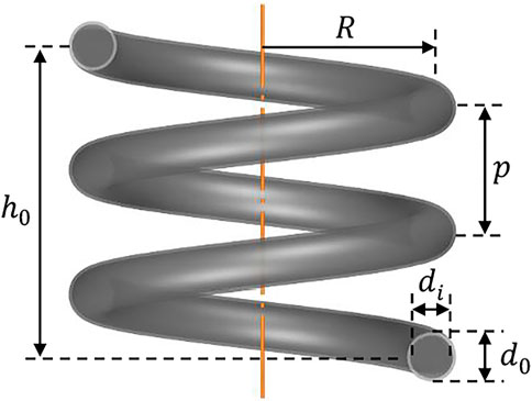
FIGURE 1. Hollow spring geometry.
This study aimed to experimentally demonstrate the capabilities of MR fluid filled spring in static and dynamic loading cases, validate derived analytical model, extend the analysis to the device’s design optimization, and estimate potential performance. The testing and analysis were performed on a MR fluid filled spring with given parameters (Table 1). Moreover, the previous analysis had shown that MR fluid’s stiffness inside the spring is dominantly produced due to cross-sectional torsion (Sikulskyi and Kim 2017). Therefore, the shear mode of MR fluid operation is preferable and can be most closely approximated by a unidirectional magnetic field in-plane with the spring cross-sections (Figures 2B,C. Hence, in the present experiments, the unidirectional magnetic field was produced by a solenoid in which the MR fluid filled spring was placed (Figure 2A). In addition to a favorable torsional stiffness of MR fluid, the in-plane magnetic field provides a better agreement of the device’s analytical model with its actual behavior and MR fluid properties that are typically measured in the shear mode.
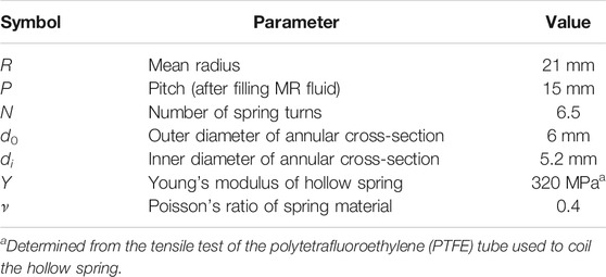
TABLE 1. Parameters of the hollow spring.
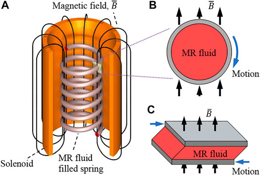
FIGURE 2. (A) Spring-solenoid system and generated magnetic field, (B) in-plane magnetic field produced by the solenoid and the cross-section motion during spring elongation, (C) shear mode of MR fluid operation.
The device’s analysis and potential performance estimation were done utilizing the derived analytical model (Eqs 1–4) (Sikulskyi and Kim 2017). The major assumptions, capabilities, and limitations of the model are shown below:
• Hollow spring. The model accurately describes the behavior of various designs (wide range of pitch and spring index) of the helical hollow spring with a constant pitch, radius, and annular cross-section (Figure 1). The model is derived utilizing the energy method-based stiffness expression for the hollow spring (Eq. 3). Due to low strains occurring in a hollow spring during deformation, its material is assumed linear in the analysis.
• MR fluid. Modeled as a Bingham viscoplastic material (Figure 3A), MR fluid contributes to the stiffness of the spring with three components. First, the stiffness of MR fluid that experiences the shear stress smaller than the yield stress is calculated as a solid spring using Wahl’s corrected formula with the shear modulus being equal to the MR fluid storage modulus. Post-yield MR fluid contributes to the stiffness with its yield stress and post-yield plastic viscosity,
• Frequency. As the post-yield plastic viscosity,
• Amplitude. A helical spring produces small strains during its oscillations enabling shear storage modulus and yield stress not to decrease with the spring’s amplitude and stay functions of applied magnetic field only (Korobko et al., 2019; Upadhyay and Choi 2021). The model accurately describes the MR fluid filled spring up to one half of the spring’s relative deflection. That is possible thanks to a helical spring’s negligible changes in its geometrical parameters, such as pitch angle, radius, and number of coils, during deformation (Morehead 1980). If larger amplitudes are of interest, the following model modification can be implemented. Firstly, a solution for a helical spring large deflection, e.g., (Morehead 1980), can be used to calculate stiffnesses of the hollow spring (Eq. 3) and pre-yield MR fluid (last component in Eq. 1). Secondly, hollow spring material nonlinearity can be added to Eq. 3 while the post-yield MR fluid behavior is already taken into account in Eq. 2.
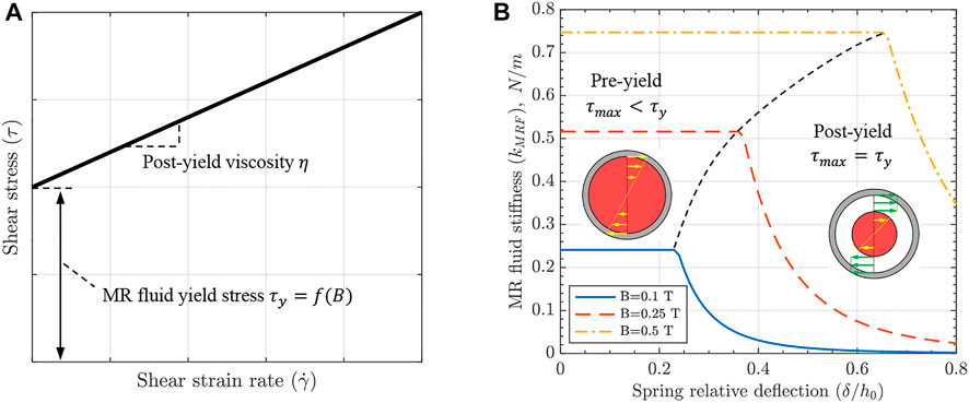
FIGURE 3. (A) Bingham viscoplastic model utilized for MR fluid mechanics in the analytical model of the device; (B) MR fluid stiffness component vs. spring deflection at various magnetic fields. According to the analytical model (Eqs 1–4), two cross-sections of the spring are illustrated for pre- and post-yield regions with shear stress distribution and solid (pre-yield) MR fluid shown in red.
As the spring elongates, MR fluid stress gradually increases and can reach its yield value, reducing the MR fluid’s stiffness component, as shown in Figure 3. Pre-yield and post-yield stiffnesses of MR fluid can be calculated according to Eqs 1, 2, respectively. It can be noticed that MR fluid stiffness at various magnetic fields is controlled by its shear storage modulus,
* The last component of Eq. 2 is corrected from the previous paper (Eq. 37 in (Sikulskyi and Kim 2017))
where
where
Lastly, to estimate the device’s potential, the MR fluid effect is maximized through an optimum design of the hollow spring. As determined, the spring’s cross-sectional void ratio is the primary factor in controlling MR fluid effect and is constrained by the spring’s local buckling. Therefore, critical void ratios are found analytically and through non-linear buckling FEM simulation.
MR fluid filled spring. Polytetrafluoroethylene (PTFE) tube with an annular cross-section (
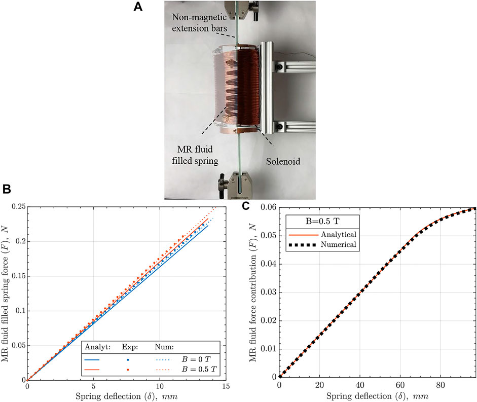
FIGURE 4. (A) Static test setup with the spring placed inside the solenoid and connected to a tensile machine through non-magnetic extension bars (left side is transparent to show the spring), (B) static response of MR fluid filled spring (smaller spring deflection range is used to keep the spring within the uniform magnetic field of the solenoid during the experiment), (C) numerical and analytical estimation of MR fluid force vs. spring deflection.
Solenoid. Gauge 22 copper isolated wire was coiled using a lathe machine on a 3″ copper tube to avoid magnetization effects during the experiment. The resultant 140 mm length solenoid had six coil layers and produced a magnetic field with an average magnetic flux density at a spring location of 0.5 T at 5.9 Amp applied current. The magnetic flux density was calculated as for finite solenoid to verify the magnetic field’s sufficient uniformity during spring static and dynamic elongation (Derby and Olbert 2010). Magnetic permeability of
Static testing. The spring was placed into the tensile machine AMETEK CS225 Series through non-metallic extension grips to minimize the magnetic force effect. The solenoid was installed on a fixture, aligned with the spring inside, and connected to an in-house-built DC power supply, with the output checked continuously with a multimeter. The testing was performed at a 30 mm/min extension rate with a 1 kg load cell. The load cell readings were zeroed when the magnetic field was applied prior to each test.
Dynamic testing. The first (natural frequency) test utilized dynamic shaker kit Modal Exciter 2060E, force sensor PCB 208C01, and miniature, lightweight accelerometer PCB 352A24. The force sensor was placed between the shaker’s stinger and the spring connection to measure excitation force. The accelerometer was glued to the middle spring coil with a Petro wax adhesive Model 080A109. The sensors’ data was collected through data acquisition system National Instrument (NI) DAQ-9174 with modules NI 9260 and NI 9234, and ICP sensor signal conditioners OCB Model 480E09. Shaker’s amplitude-frequency profile was controlled through a MATLAB/LabVIEW code (Malik 2019). The frequency was varied from 1 to 20 Hz with the initial amplitude of 1 mm. In the second (damping) test, the shaker was controlled by signal generator Kikusui FGA5050 while laser sensor MTI Instruments DTS-120–40 monitored vibration amplitude of the spring’s free end at the data recording rate of 200 Hz. The laser was pointed on a lightweight disk taped to the bottom spring coil to minimize the influence of spring in-plane motion on the data recording.
A tensile test was performed on the MR fluid filled spring, as shown in Figure 4A to validate the derived analytical model. The numerical FEM simulation was carried out in ANSYS. As in the analytical model, the hollow spring’s material was modeled as linear elastic and the MR fluid as an ideal plastic material. Due to its high density, the MR fluid considerably increased the pitch of the PTFE spring after the filling. The increased pitch was averaged along the spring and considered in both analytical and numerical analyses. The magnetic field produced a minor spring extension, and thus its effect on spring pitch was neglected. Experimental, analytical, and numerical force-spring deflection responses of the MR fluid filled spring in its active and passive states are plotted in Figure 4B.
The experimental results are compared over the spring deflection range so that the spring elongates within the uniform magnetic field of the solenoid. As seen, while all stiffness values are close to each other, there is a slight deviation (Table 2). The higher stiffness of the in-house manufactured spring can be attributed to thicker hollow spring walls within the manufacturing tolerance and an imperfect annular cross-section of the hollow spring achieved during the spring coiling. Numerical stiffness is slightly larger than the analytical result due to the fixed condition on one of the spring’s ends that restrains the spring’s end rotation, allowing solver convergence in the simulation. Meanwhile, the MR fluid stiffness effect is similar across the three analysis methods (Table 2), validating the derived analytical model within the pre-yield MR fluid region (Eq. 1). Two conclusions can be drawn when comparing analytical and numerical results at larger spring deflections, including the post-yield region (Figure 4C). Firstly, although the analytical model does not account for geometrical nonlinearity, it shows a good match with the numerical solution that accounts for large deflection. This result agrees with the known feature of helical spring preserving its geometrical parameters, such as pitch angle, radius, and number of coils, during deformation (Morehead 1980). Secondly, the FEM simulation is verified by the analytical results to be used for further device’s analysis.
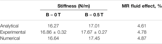
TABLE 2. Static performance of MR fluid filled spring.
As the most popular MR fluid devices’ application is semi-active vibration control, the MR fluid filled spring’s dynamic characteristics are of great interest (Wang and Meng 2001; Carlson and Jolly 2000). First, numerical analysis was extended to a dynamic response with the PTFE damping coefficient of
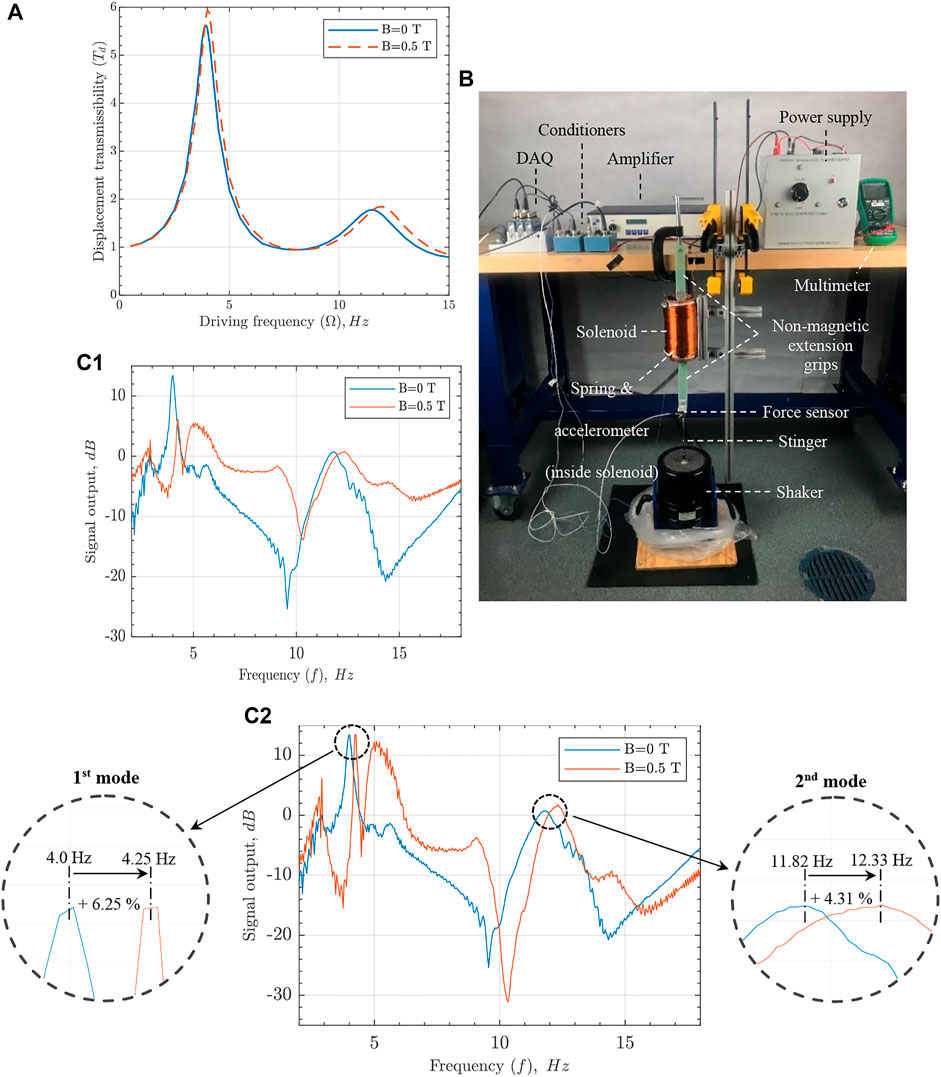
FIGURE 5. (A) Numerically obtained transmissibility plot of the MR fluid filled spring at 0 and 0.5 T magnetic field. (B) First setup for dynamic test (C1) frequency domain responses for passive and active MR fluid filled spring states, and (C2) the normalized responses.
Two experiments were performed to validate the effects of MR fluid on the device’s dynamic performance. In the first test, the MR fluid effect on the spring’s natural frequencies was investigated by fixing the spring vertically by one end and exciting through the other end with a dynamic shaker, as shown in Figure 5B. Next, the spring’s dynamic response in time domain was converted to the frequency response function (Figure 5C1) by utilizing MATLAB’s built-in empirical transfer function estimation (etfe). Unfortunately, the data could not be used to extract the damping ratio using the half-power method because the signal output (force sensor) was affected by the magnetic field. For convenience, the frequency response function was normalized (Figure 5C2) to demonstrate a noticeable increase of both first and second natural frequencies in the presence of the magnetic field. Additionally, few other peaks appeared when the solenoid was activated. These peaks represent in-plane spring vibration modes (as observed during testing and compared with a numerical modal analysis) magnified by the magnetic field’s small radial component, which varies axially along the solenoid.
When the experimental results of the first and second modes are compared with analytical and numerical (Table 3), larger shifts in natural frequencies in the experiment become evident. Being made of a relatively soft polymer, having a helical shape, and filled with heavy MR fluid, the spring possesses a fairly low stiffness and natural frequencies (as shown in Tables 2, 3). Therefore, the gravity effect on structural vibration should be considered for the correct result. With the spring oriented vertically and fixed by its top edge in the test, the gravity effect contributes to the higher experimental natural frequencies at zero magnetic field but does not explain the larger frequency shifts (Virgin et al., 2007). As the applied uniform magnetic field is an extra downward body force acting on the MR fluid particles, it applies additional tension in the spring and affects the spring’s natural frequencies in a similar way to gravity. As such, the MR fluid filled spring provides an even higher increase in natural frequency when operated under the uniform aligned magnetic field.
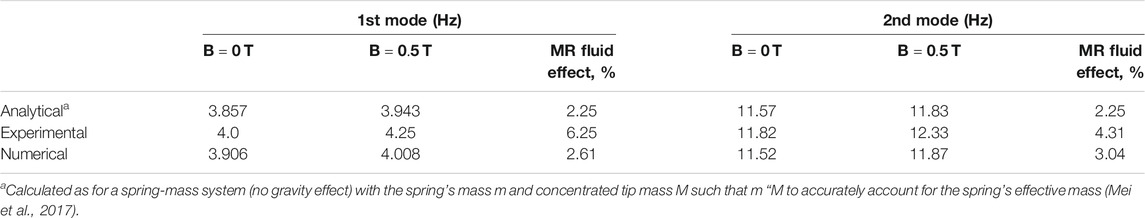
TABLE 3. Natural frequency shift due to MR fluid effect.
Figure 6B shows the spring amplitude recorded by the laser displacement sensor during the testing at various magnetic fields. An apparent vibration amplitude suppression with the increasing magnetic field (Figure 6C) validates the MR fluid filled spring damping capability. The magnitude of the damping, however, was somewhat higher than expected. As the hollow spring material (PFTE) has a structural damping coefficient of about 0.224 (Fu and Chung 2001), a considerable loss modulus is needed for MR fluid to noticeably contribute to the device’s damping. Based on the MR fluid viscoelastic properties used in this analysis, the storage modulus accurately describes the change in device stiffness, but the loss modulus is insufficient to produce the demonstrated damping (Laun et al., 2009). While some studies report a frequency and magnetic field dependent loss modulus of MR fluid that could cause substantial damping (Naji et al., 2016), most reports within the literature share relatively low values of loss modulus and loss factor of MR fluid, particularly MRF-132DG (Sun et al., 2003; Shah and Choi 2014; Li et al., 1999). Therefore, this work argues that the specific direction of the magnetic field (in-plane with the spring’s cross-sections) aligns MR fluid particles’ chains in such a way as to facilitate energy dissipation.
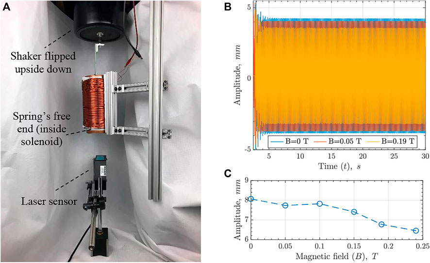
FIGURE 6. (A) Second setup for damping test, (B) MR fluid spring’s vibration amplitude as recorded at various magnetic fields (at which MRF-132DG viscoelastic properties were measured in the reference paper (Laun et al., 2009)), and (C) peak-to-peak amplitude plotted as a function of the magnetic field.
Maximizing the performance of novel devices through design optimization is essential for their further development. The analytical model suggests that to increase the MR fluid effect, a smaller shear modulus of the spring material and a larger void ratio of the annular cross-section must be used. However, such changes of these two hollow spring parameters decrease its buckling load, which becomes the major limitation in choosing the spring’s appropriate material and void ratio. Hence, the stability of the MR fluid filled spring should be investigated. The worst-case scenario for the MR fluid filled spring buckling would be when MR fluid is in the passive state and has the lowest mechanical properties. Nevertheless, the empty hollow spring is considered in the buckling analysis for conservative results.
Two local buckling modes are typically considered for the hollow spring, i.e., torsional wall buckling and spring wall wrinkling under bending load (Spinella and Dragoni 2010). The latter mode often appears as a stricter constraint during spring coiling and a much softer constraint during spring operation. Therefore, if a spring manufacturing technique does not involve large deformation, wall wrinkling can be neglected in the buckling analysis. The local torsional stability can be presented with Eqs 7–9 (Spinella and Dragoni 2010),
where
Figure 7A shows operational and critical forces as functions of the hollow spring’s void ratio and Young’s modulus. The intersection between the critical and operational force surfaces represents the critical spring design parameters. As seen, the critical void ratio is 0.924 and is independent of the elastic modulus of the hollow spring. This result agrees with the linear dependency of the analytical expressions of both spring’s critical force and stiffness with Young’s modulus.
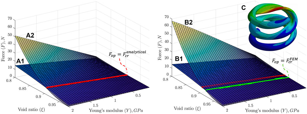
FIGURE 7. Analytical (A1) operational and (A2) critical forces for hollow springs with different void ratios and material Young’s moduli. Critical stress was converted to critical force using Eq. 9 and compared with the operational force for a direct correlation with the numerical analysis (B1) Analytical operational and (B2) numerical buckling critical forces of the hollow spring designs. The critical force surface is interpolated from discrete values of the critical force determined numerically for several Young’s moduli
However, Eq. 8 is Timoshenko’s formula which describes the local buckling of a thin-walled cylindrical shell (Timoshenko and Gere 1963). To omit the thin-walled structural analysis assumptions and consider the spring’s helical shape and large deflection, a non-linear buckling FEM simulation was carried out. As the results show (Figure 7B), the hollow spring’s final numerical buckling loads are greater than analytical, resulting in the critical void ratio of 0.934 versus the analytical value of 0.924. In addition, the buckling analysis showed that the spring index and pitch angle have a secondary effect on the critical void ratio. Particularly, as the spring’s index decreases or the pitch angle increases, the critical void ratio slightly reduces. In the present work, the spring’s index is on the lower side while the pitch angle has a moderate value; therefore, a spring with more common values for both parameters would have an even higher MR fluid effect.
Lastly, using the validated analytical model, the MR fluid filled spring’s static performance was estimated for hollow spring made of various materials. It is represented in terms of the MR fluid stiffness effect for the hollow spring with the maximum void ratio of 0.934 and made of various soft polymers (Figure 8A. As shown, the optimized void ratio increases PTFE hollow spring’s MR fluid effect from 4.61 to 11.37%, while values up to 28% are reachable for hollow springs made of soft polymer materials like LDPE. It is worth noting that the critical void ratio was found for the arbitrarily selected value of relative spring deflection of 0.4. Thus, finding critical void ratios and corresponding MR fluid stiffness effects for different spring relative deflections is an important design consideration. Critical void ratios were determined by comparing the operational force (Figure 7B1), adjusted for each new value of spring relative deflection, with the critical force (Figure 7B2). The MR fluid stiffening effect and critical void ratio of the spring are shown for different spring relative deflections in Figure 8B. The graph suggests that even with a hollow spring made of relatively stiff polymer (PTFE), the device can possess variable stiffness of up to 30% if operational spring relative deflection is less than 0.1 (10%).
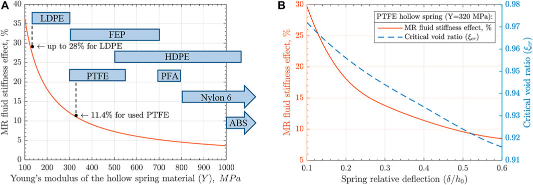
FIGURE 8. (A) MR fluid stiffness effect for a spring with the optimized void ratio
The analysis demonstrated the variable stiffness and damping properties of the MR fluid filled spring device. Spring design optimization can lead to a considerable controllable MR fluid effect making the device practical. Nevertheless, spring design optimization is mainly driven by minimizing the wall thickness, which complicates the fabrication and handling of the spring. Moreover, since MR fluid research is not focused on improving its modulus, further performance enhancement of MR fluid filled spring from a material point of view is limited. Thus, further device development is seen in utilizing magnetorheological elastomer (MRE) instead of MR fluid. Being a solid material in a passive state, MRE will resist buckling of the hollow spring, prevent oil leakage, ease device handling, and potentially enable device additive manufacturing (Böse et al., 2021; Park et al., 2022). A higher range of controllable modulus and research interest to improve this material property will enhance the variable stiffness of the device. In addition, existing validated analytical model for solid biomaterial helical spring can directly be applied for static modeling of MRE filled spring (Dragoni and Bagaria 2011; Dragoni and Bagaria 2013). However, the dynamic properties of such a device would still require further investigation.
The main objectives of this work were validating the derived analytical model, unveiling spring capabilities, and estimating the MR fluid filled spring’s potential performance. Experimental analysis of stiffness variation due to the MR fluid effect validated the analytical model. FEM simulation that utilized the ideal plastic material model of MR fluid was verified by the static analytical result and assisted in the further analysis of the device. In dynamic testing, the MR fluid filled spring’s capabilities to shift resonance frequencies and improve damping characteristics were demonstrated. The former improvement showed higher than expected performances, which was explained by the specifics of the utilized unidirectional magnetic field. Finally, the buckling analysis was performed on a hollow spring to determine its critical void ratio and maximize MR fluid effect. An analytical approach and non-linear FEM simulation were employed for this task, with the latter showing the higher value of the critical void ratio while considering the hollow spring’s large deflections and helical shape features. The performance estimation showed that the variable stiffness of the MR fluid filled spring can reach about 30% for different combinations of hollow spring materials and operational conditions (relative deflections). Similar to the demonstrated increase in dynamic performance of the tested spring, the authors believe that the optimized spring is expected to improve its dynamic performance even more than the increase in the stiffness effect. Lastly, utilization of MRE was foreseen as the next stage of the device’s development.
The original contributions presented in the study are included in the article/Supplementary Material, further inquiries can be directed to the corresponding author.
SS Conceptualization, methodology, analysis, writing-reviewing-editing. AM methodology, analysis, writing-reviewing-editing. DK Conceptualization, methodology, writing-reviewing-editing.
The authors declare that the research was conducted in the absence of any commercial or financial relationships that could be construed as a potential conflict of interest.
Authors would like to thank Michael Potash, Electronics Design Lab Manager and Electronics Technician at Embry-Riddle Aeronautical University, for designing and building the power supply used in this study.
All claims expressed in this article are solely those of the authors and do not necessarily represent those of their affiliated organizations, or those of the publisher, the editors, and the reviewers. Any product that may be evaluated in this article, or claim that may be made by its manufacturer, is not guaranteed or endorsed by the publisher.
The Supplementary Material for this article can be found online at: https://www.frontiersin.org/articles/10.3389/fmats.2022.856945/full#supplementary-material
Böse, H., Gerlach, T., and Ehrlich, J. (2021). Magnetorheological Elastomers - an Underestimated Class of Soft Actuator Materials. J. Intell. Mater. Syst. Structures 32 (14), 1550–1564. doi:10.1177/1045389x21990888
Carlson, J. D., and Mark Jolly, R. (2000). Mr Fluid, Foam and Elastomer Devices. Mechatronics 10, 4555–4569. doi:10.1016/S0957-4158(99)00064-1
Derby, N., and Olbert, S. (2010). Cylindrical Magnets and Ideal Solenoids. Am. J. Phys. 78 (3), 229–235. doi:10.1119/1.3256157
Dragoni, E., and Bagaria, W. J. (2011). Mechanical Design of Bimaterial Helical Springs with Circular Cross-Section. J. Strain Anal. Eng. Des. 46 (4), 304–314. doi:10.1177/0309324711400968
Dragoni, E., and Bagaria, W. J. (2013). Numerical and Experimental Validation of a Theoretical Model for Bimaterial Helical Springs. J. Strain Anal. Eng. Des. 48 (3), 166–176. doi:10.1177/0309324712469510
Fu, W., and Chung, D. D. L. (2001). Vibration Reduction Ability of Polymers, Particularly Polymethylmethacrylate and Polytetrafluoroethylene. Polym. Polym. Composites 9 (6), 423–426. doi:10.1177/096739110100900607
Golinelli, N., and Spaggiari, A. (2015). Design of a Novel Magnetorheological Damper with Internal Pressure Control. Frattura Ed. Integrità Strutturale 9, 13–23. doi:10.3221/IGF-ESIS.32.02
Hong, S.-W., Yoon, J.-Y., Kim, S.-H., Lee, S.-K., Kim, Y.-R., Park, Y.-J., et al. (2019). 3d-Printed Soft Structure of Polyurethane and Magnetorheological Fluid: A Proof-Of-Concept Investigation of its Stiffness Tunability. Micromachines 10, 655. doi:10.3390/mi10100655
Hua, D., Liu, X., Li, Z., Fracz, P., Hnydiuk-Stefan, A., and Li, Z. (2021). A Review on Structural Configurations of Magnetorheological Fluid Based Devices Reported in 2018-2020. Front. Mater. 8. [In English]. Review. doi:10.3389/fmats.2021.640102
Jackson, J. A., Messner, M. C., Dudukovic, N. A., Smith, W. L., Bekker, L., Moran, B., et al. (2018). Field Responsive Mechanical Metamaterials. Sci. Adv. 4 (12), eaau6419. doi:10.1126/sciadv.aau6419
Kaluvan, S., Park, C.-Y., and Choi, S.-B. (2016). Bio-Inspired Device: A Novel Smart Mr Spring Featuring Tendril Structure. Smart Mater. Struct. 25, 01LT01. doi:10.1088/0964-1726/25/1/01LT01
Kumar, J. S., Paul, P. S., Raghunathan, G., and Alex, D. G. (2019). A Review of Challenges and Solutions in the Preparation and Use of Magnetorheological Fluids. Int. J. Mech. Mater. Eng. 14 (1), 13. doi:10.1186/s40712-019-0109-2
Laun, H. M., Gabriel, C., and Kieburg, C. H. (2009). Magnetorheological Fluid (MRF) in Oscillatory Shear and Parameterization with Regard to MR Device Properties. J. Phys. Conf. Ser. 149, 012067. doi:10.1088/1742-6596/149/1/012067
Li, W. H., Chen, G., and Yeo, S. H. (1999). Viscoelastic Properties of Mr Fluids. Smart Mater. Struct. 8 (4), 460–468. doi:10.1088/0964-1726/8/4/303
LORD, C. (2011). Mrf-132dg Magneto-Rheological Fluid. Available at: http://www.lordmrstore.com/lord-mr-products/mrf-132dg-magneto-rheological-fluid (Accessed 01 22, 2021).
Malik, Aryslan. (2019). Experimental and Computational Analysis of a 3d Printed Wing Structure. Ph.D. (Florida: Embry-Riddle Aeronautical University).
Mei, L., Zhu, J., and Liu, F. (2017). Discussion on Vibration Frequency of Spring. AIP Conf. Proc. 1834 (1), 030006. doi:10.1063/1.4981571
Morehead, H. L. (1980). Large Deflections of Helical Springs. Ph.D. (Illinois: University of Illinois at Urbana-Champaign), 8026562.
Naji, J., Zabihollah, A., and Behzad, M. (2016). Layerwise Theory in Modeling of Magnetorheological Laminated Beams and Identification of Magnetorheological Fluid. Mech. Res. Commun. 77, 50–59. doi:10.1016/j.mechrescom.2016.09.003
Park, J., Becnel, A., Flatau, A. B., and Wereley, N. (2022). Magnetic Particle Reinforced Elastomer Composites for Additive Manufacturing. IEEE Trans. Magn. 58, 1–5. doi:10.1109/TMAG.2021.3084506
Park, J., Choi, Y. T., Flatau, A. B., and Wereley, N. M. (2021). Encapsulations of Magnetorheological Fluids within 3d Printed Elastomeric Cellular Structures. IEEE Trans. Magn. 2021, 1. doi:10.1109/TMAG.2021.3137838
Phu, D. X., and Choi, S.-B. (2019). Magnetorheological Fluid Based Devices Reported in 2013-2018: Mini-Review and Comment on Structural Configurations. Front. Mater. 6. [In English]. Review. doi:10.3389/fmats.2019.00019
Shah, K., and Choi, S.-B. (2014). The Field-dependent Rheological Properties of Magnetorheological Fluids Featuring Plate-like Iron Particles. Front. Mater. 1 (21). [In English]. Original Research. doi:10.3389/fmats.2014.00021
Sikulskyi, S., and Kim, D. (2017). “Analytical Approach on the Stiffness of Mr Fluid Filled Spring,” in SPIE Smart Structures and Materials + Nondestructive Evaluation and Health Monitoring, SPIE. doi:10.1117/12.2260215
Simon, T. M., Reitich, F., Jolly, M. R., Ito, K., and Banks, H. T. (2001). The Effective Magnetic Properties of Magnetorheological Fluids. Math. Comput. Model. 33, 273–28484. doi:10.1016/S0895-7177(00)00244-2
Spinella, I., and Dragoni, E. (2010). Analysis and Design of Hollow Helical Springs for Shape Memory Actuators. J. Intell. Mater. Syst. Structures 21, 185–199. doi:10.1177/1045389X09356021
Sun, C. T., Sun, C. T., and Lu, Y. P. (1995). Vibration Damping of Structural Elements. Hoboken, NJ, USA: Prentice Hall PTR.
Sun, Q., Zhou, J.-X., and Zhang, L. (2003). An Adaptive Beam Model and Dynamic Characteristics of Magnetorheological Materials. J. Sound Vibration 261, 465–481. doi:10.1016/S0022-460X(02)00985-9
Susan-Resiga, D., Bica, D., and Vékás, L. (2010). Flow Behaviour of Extremely Bidisperse Magnetizable Fluids. J. Magnetism Magn. Mater. 322, 3166–3172. doi:10.1016/j.jmmm.2010.05.055
Timoshenko, S. P., and Gere, J. M. (1963). Theory of Elastic Stability. Mineola, NY, USA: Dover Publications.
Virgin, L. N., Santillan, S. T., and Holland, D. B. (2007). Effect of Gravity on the Vibration of Vertical Cantilevers. Mech. Res. Commun. 34 (3), 312–317. doi:10.1016/j.mechrescom.2006.12.006
Keywords: magnetorheological (MR) fluid, MR fluid device, variable stiffness, variable damping, semi-active damping, hollow spring buckling, spring optimization
Citation: Sikulskyi S, Malik A and Kim D (2022) Magnetorheological Fluid Filled Spring for Variable Stiffness and Damping: Current and Potential Performance. Front. Mater. 9:856945. doi: 10.3389/fmats.2022.856945
Received: 17 January 2022; Accepted: 17 February 2022;
Published: 11 March 2022.
Edited by:
Marcelo J. Dapino, The Ohio State University, United StatesReviewed by:
Eugenio Dragoni, University of Modena and Reggio Emilia, ItalyCopyright © 2022 Sikulskyi, Malik and Kim. This is an open-access article distributed under the terms of the Creative Commons Attribution License (CC BY). The use, distribution or reproduction in other forums is permitted, provided the original author(s) and the copyright owner(s) are credited and that the original publication in this journal is cited, in accordance with accepted academic practice. No use, distribution or reproduction is permitted which does not comply with these terms.
*Correspondence: Stanislav Sikulskyi, c2lrdWxza3NAZXJhdS5lZHU=
Disclaimer: All claims expressed in this article are solely those of the authors and do not necessarily represent those of their affiliated organizations, or those of the publisher, the editors and the reviewers. Any product that may be evaluated in this article or claim that may be made by its manufacturer is not guaranteed or endorsed by the publisher.
Research integrity at Frontiers
Learn more about the work of our research integrity team to safeguard the quality of each article we publish.