 Chunyu Li1
 Bingsan Chen
95% of researchers rate our articles as excellent or good
Learn more about the work of our research integrity team to safeguard the quality of each article we publish.
Find out more
ORIGINAL RESEARCH article
Front. Mater. , 02 March 2022
Sec. Smart Materials
Volume 9 - 2022 | https://doi.org/10.3389/fmats.2022.854872
This article is part of the Research Topic Preparation, Properties and Applications of Electro-Responsive Smart Materials View all 6 articles
In order to improve the transmission torque caused by the electrorheological effect, a corrugated disk is proposed to replace traditional flat disk by changing the electrode surface shape. The new mechanism puts the device in a shear-squeeze mode of operation. Based on the constitutive equation of electrorheological fluids, the shear motion characteristics of the ER fluids between the flat disk and the corrugated disk are analyzed, including the pressure distribution, torque equations, and the comparison with double-flat-disk mechanism. The analysis shows that compared with the double-flat-disk structure, the flat-disk-corrugated-disk structure can enhance the transmitted torque over 2.6 times under the same operating parameters. The magnification of the torque is not related with the curve number of the corrugated disc, but mainly depends on the structural parameters of the device and corrugations, and the characteristic parameters of electrorheological fluid. It is proved that the mechanism can provide new ideas and new methods for the engineering application of electrorheological transmission technology.
Electrorheological (ER) fluids are one kind of smart materials, which are mainly composed of polarizable particles uniformly dispersed in the insulating oil body to form a type of two-phase fluid (Stangroom, 1983). The rheological properties of such fluids can undergo instantaneous and reversible changes under the action of an electric field. Under the electric field, the polarizable particles inside the ER fluids will attract each other to form a chain structure arranged along the direction of the electric field. These chain structures enable the fluids to resist shear (Klingenberg, 1996). Since the ER fluids with good performance can respond quickly and reversibly, they have a wide range of applications in mechanical engineering, automotive engineering and other fields (Lei, 2008; Chen, 2017; Kolekar and Choi, 2019).
The technology has significant advantages such as: simpler structure, quicker response, better controllability and intellectual technology (Kesy et al., 2022a). As being developed greatly these years, ER technology has attracted more and more attention from scientists and engineers in the world. But research mainly focuses on how to improve the shear performance of the material itself. For instance, Titanium silicalite-1 (Liu, et al., 2020), porous chitosan particles (Kuznetsov, 2021), deagglomerated nano-diamond particles (Nikita, 2021) are used to enhance the characteristics of the ER fluids. Aluminum-doped and TiO2 cerium-doped TiO2 are utilized to synthesize giant ER fluids in order to obtain large interfacial polarization (Tang, et al., 2010; Yin and Zhao, 2004). The above methods have been confirmed by experiments, and the performance of ER fluids can be greatly improved. Still, many researchers focus on the model and analysis of the ER fluids, including the viscoelastic behavior, the problems under steady flow, et al. (Ginder, 1995; Sin, 2019; Seo and Seo, 2022). The research results provide a valuable theoretical basis for a better understanding of the rheological effects and the engineering applications of ER fluids.
Due to high sensitivity (millisecond response), low energy consumption, simple structure, and low price of ER fluids, ER devices can facilitate the realization of mechanical-electrical conversion, such as the performance optimization of shock absorbers, clutches, and dampers (Kamelreiter et al., 2012; Kesy, et al., 2022b). Papadopoulos designed and manufactured multi-disc ER brakes or clutches. By applying an electric field between the input and output components to change the viscosity of the ER fluids, the output torque of the brake or the angular velocity of the clutch can be adjusted (Papadopoulos, 1987); Tan et al. used an ER clutch to control the robot arm, which improved the positioning accuracy and increased the flexibility and load capacity of the robot (Tan et al., 2002; Tan, et al., 2005). Zhao et al. first developed an adaptive damper combined with ER fluids and piezoelectric ceramics. Under the action of external force, piezoelectric ceramics can generate high voltage and output different voltages in response to external force, which can achieve the purpose of closed-loop control (Zhao, et al., 2006). Liu et al. proposed an ER fluids cylindrical clutch, which can keep the shear stress stable at high shear rates, and exhibits excellent performance compared with traditional electrorheological clutches (Liu, et al., 2005). Experiments show that ER devices have great advantages in replacing traditional related devices.
The purpose of this paper is to study the enhancement of transmission torque caused by the ER effect in the ER actuator (hereinafter referred to as ER torque) from the perspective of mechanism optimization. Then, a corrugated disc is proposed to replace the traditional flat disk, changing the device into a shear-squeeze working mode. Compared with the double flat plate ER actuator in the shearing mode, it is expected that the shearing torque can be greatly improved under such a design.
The mechanical properties of ER fluids are complex: without electric field, ER fluids render a Newtonian fluid; when applied with an electric field, they behave as a Bingham fluid, as shown in Figure 1; Under low strain rate, ER fluids have viscoelastic properties; Under high electric field, ER fluids are a viscoplastic body with high yield stress. This phenomenon is called the ER effect (Ginder, 1995).
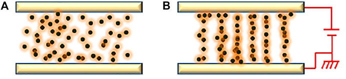
FIGURE 1. Er effects of ERF (A) without electric field; (B) under electric field.
According to the characteristics of ER fluids, ER mechanism can be divided into three types, namely: flow mode, shear mode and extrusion mode (Conrad and Sprecher, 1991), among which the shear mode is the most widely used. Taking the disk as an example, the transmission mechanism is shown in Figure 2. It has two parallel disks, A and B. Disk A is sleeved on the rotating shaft of the disk B. The inner diameter of the disk A is r2, the outer diameter of the disks A and B are both r, and the distance between the two disks is h. Disk A is the drive disk and disk B is the driven disk. When an electric field is applied between the two disks where filled with ER fluids, the moment T generated by the electro-yield stress and viscous shear stress of the ER fluids drives the disk B to rotate, and the right end of disk B shaft thereby drives the load end. The magnitude of the torque is controlled by the applied voltage according to the specific situation.
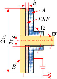
FIGURE 2. Diagram of disc type ER transmission device.
Assume that the angular velocities of the drive and driven disks are Ω and ϖ, respectively. ηα is the viscosity of the ER fluids. ΔΩ = Ω-ϖ, is the angular velocity difference of the drive-driven disc, and ΔΩ is assumed to be distributed linearly along the axis, and according Bingham constitutive equation:
where τ0 denotes the yield stress caused by the applied electric field; ηα denotes the plastic viscosity, which is the ratio of shear stress to shear strain rate;
It can be seen from Eq. 2 that the torque T increases with the decrease of the inner diameter r2 and the increase of the outer diameter r1, which is due to the increase of the effective area of the ER effect. Therefore, in order to increase the effective area, this paper proposes the design concept of the flat disk-corrugated disk transmission mechanism.
As shown in Figure 3A, one end (or both ends) of the two counter-rotating discs is corrugated, and the two discs are filled with ER fluids. Figure 3B is a wireframe diagram of the corrugated disc, and Figure 3C is a plan view of the unfolding corrugation. Many recent experimental studies have shown that the yield stress under squeeze flow can be several times larger than that under shear flow, and the electric field and bulk density increase with increasing strain (Sproston, et al., 1999).
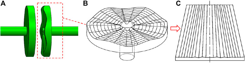
FIGURE 3. Characteristics of the corrugated disc. (A) Flat-Corrugated transmission pair; (B) Wireframe of a corrugated disc; (C) Unfolding surface.
Unlike parallel shear flow including Poiseuille flow and Coutette flow, squeeze flow problems have their own special complexities (Hoppe and Litvinov, 2011). For example, when studying the Poiseuille flow of a yield stress fluid between parallel plates, the location of the yield surface in the flow field can be determined based on the common Bingham model. Taking the yield surface as the boundary, the two sides are the yield area and the unyielding area, and the fluid moves like a solid in the unyielding area. In the squeeze flow problem, if the Bingham model is adopted, it will lead to non-physical result of no relative motion between the two discs, so-called yield surface paradox (Gartling and Phan-Thien, 1984). The appearance of the paradox indicates that the Bingham model is too ideal and cannot correctly describe the physical nature of the problem. Therefore, a generalized bi-viscosity model is used and described as follows (Zhu, 1999):
where
where
The ER fluids’ Motion analysis between the flat-corrugated disks.
First, the shear motion between the flat -corrugated-disk is discussed. Figure 4 is a partial cross-sectional view of the combined structure along the circumferential direction, the upper plate is a corrugated disk, the lower plate is a flat disk, and the moving speeds of the upper and lower disks are ub and ua respectively. The working surface of the corrugated disk is processed with corrugations radiating outward from the center. The shape and number of corrugations can be changed. Takes sinusoidal corrugations as an example for analysis and experiments. In order to prevent the unbalance during the rotation, the number N of corrugated heads is designed to be an odd number. The corrugation amplitude is hm, the distance from the corrugation center to the flat disk, i.e. the average gap is hc, and λ = hm/hc < 1. Assuming that the corrugated disk is fixed, the flat disk is taken as the active disk, and its rotational angular velocity is Ω. The following assumptions are applied to the motion is:
l) The flow state is laminar flow without eddy current and turbulent flow;
2) Mass force (such as gravity) can be ignored;
3) Inertial force can be neglected compared with viscous force and electric force, therefore
4) The pressure, density and viscosity are constant along the y direction, namely
5) The inelastic sliding of ER fluids between the plates means that the fluid does not slide along the interface and the disk surface; the velocity of the fluid is the same as that of the disk surface;
6) In ER fluids, the x-direction velocity ux is much larger than the z-direction velocity uz and the y-direction velocity uy, and y is much smaller than the dimensions of x and z, therefore compared with the velocity gradient
7) The boundary condition of ER fluids motion is that when y = 0,
where p denotes the pressure, τ denotes the shear stress, and

FIGURE 4. The shearing movement between Flat and Corrugated discs.
Therefore, the pressure distribution law of the fluid during the shearing motion of the ER fluids between the flat and corrugated disks is:
It can be seen from Eq. 7 that the pressure between the flat and the corrugated disk the pressure increases with the increase of the rotation speed of the active disk, and/or the decrease of the average gap hc; it is related to the phase of the corrugation.
Analysis of moment between plane and corrugated disk.
The moment between the flat and corrugated disks includes the moment caused by the squeezing force and the moment caused by the shearing motion. By derivation, the moment produced by the squeezing force can be expressed by the following formula
Likewise, the viscous shear moment between the flat and corrugated disks can be described as
From Equations 9, 10, it can be found that the squeeze moment and the shear moment are independent of the number of corrugated heads N, and are proportional to liquid viscosity; the moment increases with the ratio λ of corrugation amplitude hm to hc. The larger the effective area of the disk, the greater the torque.
In order to test the torque transmission performance of the flat disk and the corrugated disk, a test platform is designed as shown in Figure 5. The measurement and control system of the ER transmission mechanism, are realized through three boards from NI Company in the United States: Arbitrary Waveform Generator (PCI-5411), Action Control Card (PCI-FlexMotion-6C) and Data Acquisition Card (PCI-MIO-16E-1).
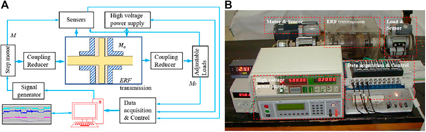
FIGURE 5. Experimental setup diagram and its photo. (A) is the test principle diagram (B) is the photo of the test platform.
During the experiments, the HITL2 ER fluids developed by the Institute of Composite Materials of Harbin Institute of Technology are selected as the working medium. Its main ingredients are nano-silica (particle material, mass ratio 13%), mechanical oil (dispersion medium, mass ratio 77%) and oleic acid (additive, mass ratio about 10%). The dynamic shear stress of the HITL2 is shown in Figure 6. It can be seen that shear stress increases with shear rate
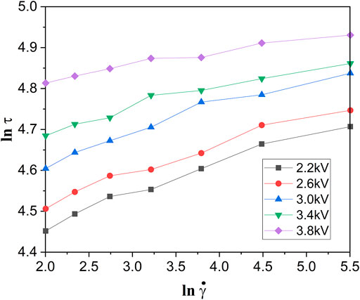
FIGURE 6. Dynamic shear stress of HITL2.
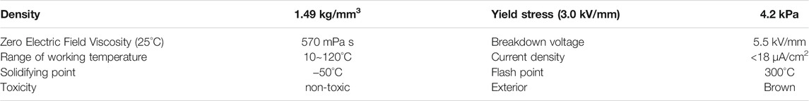
TABLE 1. Characteristics of HITL2 ER fluids.
Since temperature has a great influence on the strength and yield stress of ER fluids (Chen et al., 1991; Conrad and Sprecher, 1991), at the same time, it has a certain influence on the apparent viscosity, dielectric constant and electrical loss of ER fluids. In order to reduce the influence of temperature, the experimental ambient temperature was set to 21°C.
The inner and outer diameters of the corrugated disk are 62 and 130 mm, respectively; the number of corrugated heads on the left and right discs is N = 9, N = 17, as shown in Figure 7. Inter-disc clearance: double flat disc clearance h = l mm, flat-corrugated disc average clearance hc = l mm (λ = 0.5). The high voltages power applied between the working gap are set as: AC/DC: 1∼4 kV.
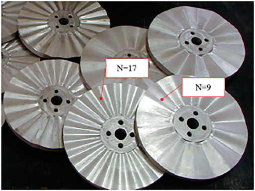
FIGURE 7. The corrugated discs.
When all the disks are set as flat disks in the ER fluids transmission, as shown in Figure 2 and Figure 5, and the experimental voltages were taken under DC/AC 2.4 kV, 2.8 kV, 3.3 kV, 3.7 kV respectively. The rotation rates of the left and right disks are set 60 rpm. The output torque curves of the mechanism are shown in Figure 8. It can be seen that with increase in voltage, the output torque increases; under the same experimental conditions, an AC voltage provides a higher output torque of the mechanism than a DC voltage.
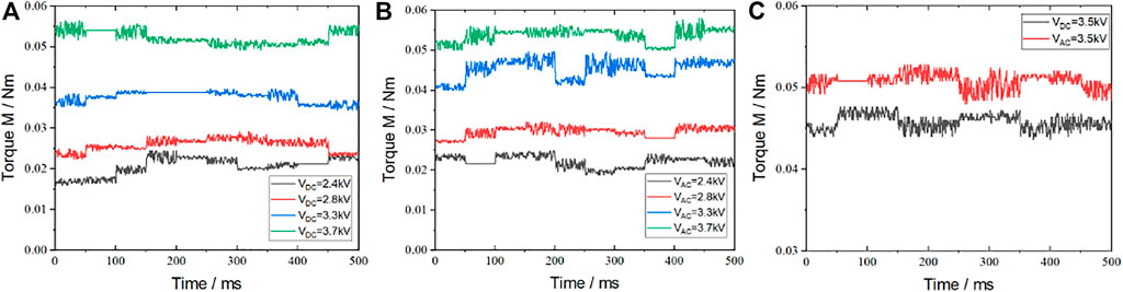
FIGURE 8. The output torque curves of ERF transmission with flat discs. (A) Output torque under DC (B) Output torque under AC (C) the comparison of DC&AC.
When the driving disk is a flat disk and the driven disk is a corrugated disk (N = 9) in the ERF transmission shown in Figure 2 and Figure 5, and the experimental voltages were taken as DC/AC 2.4 kV, 2.8 kV, 3.3 kV, 3.7 kV respectively. The torque curve is shown in Figure 9. The experimental results show the same law as the double-flat mechanism. Compared with Figure 8, it can be found that under the same experimental conditions, the output torque of the flat-corrugated disk mechanism is significantly larger than that of the double-flat disk structure.
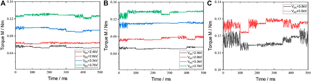
FIGURE 9. The output torque curves of ERF transmission with the flat-corrugated disk. (A) Output torque under DC (B) Output torque under AC (C) the comparison of DC&AC.
The torque output results obtained under two experimental conditions described in Section 4.1, 4.2, are compared in Table 2. It can be found that the output torque of the flat disc-corrugated disc is about 2.5 times larger than that of the double flat disc. Although the application of voltage category has an impact on the output torque, from the analysis of the average value of the torque, the magnification is around 1.1 times, which can also be verified from Figure 7C and Figure 8C.
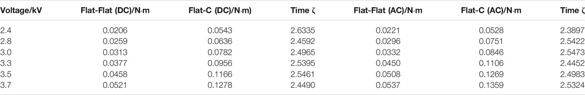
TABLE 2. Comparison of the average output torque of the flat disk and the corrugated disk under different high pressures (ζdenotes the ratio of the output torque of the flat-cross disk and the double-plane disk).
The experimental conditions are described in 4.2. When changing different corrugated discs, the output value of the moment can be obtained. Here, only the influence of the number of corrugated heads on the moment is analyzed. The experimental results are shown in Figure 10. It can be seen from the figure that the number of heads of the corrugated disc has almost no effect on the output torque of the mechanism, which is also consistent with the conclusion of the theoretical modeling.
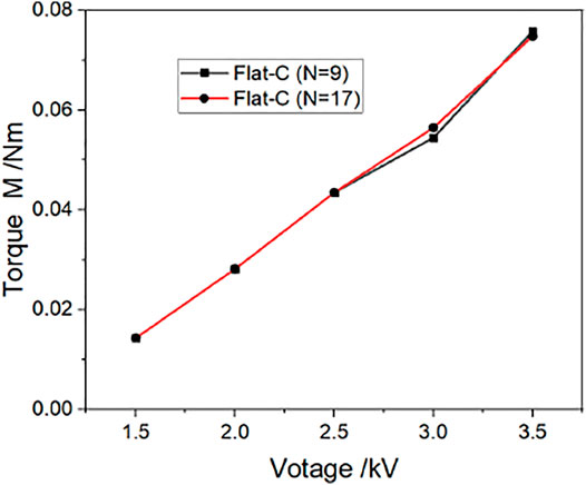
FIGURE 10. Influence of the corrugated disk heads number N on the torque.
1) Compared with the double-flat structure, the flat-corrugated-disk structure can double the torque transmitted by the ER effect under the same conditions of geometric parameters, rheological fluid material, applied electric field strength and operating parameters.
2) The magnification of torque is not determined by the number N of corrugated disks, but mainly depends on the structural parameters of the device and the corrugation and the characteristic parameters of the ER fluids.
3) Because the characteristic viscosity parameter of ER fluids is related to the electric field intensity and the rotation speed difference of the active and passive discs, the torque magnification of the ER effect will fluctuate under different electric field intensity and rotation speed difference.
The raw data supporting the conclusions of this article will be made available by the authors, without undue reservation.
CL and BC did the experiment and written the paper. YH designed the mechanism.
This project was supported by the Natural Science Foundation of Fujian Province (2020J01874) and Program for Innovative Research Team in Science and Technology in Fujian Province University ((2020) No. 12).
The authors declare that the research was conducted in the absence of any commercial or financial relationships that could be construed as a potential conflict of interest.
All claims expressed in this article are solely those of the authors and do not necessarily represent those of their affiliated organizations, or those of the publisher, the editors, and the reviewers. Any product that may be evaluated in this article, or claim that may be made by its manufacturer, is not guaranteed or endorsed by the publisher.
Chen, M.-X., Shang, Y.-L., Jia, Y.-L., Dong, X.-Y., Ren, J., and Li, J.-R. (2017). New Multifunction Materials with Both Electrorheological Performance and Luminescence Property. Korea-aust. Rheol. J. 29 (1), 29–36. doi:10.1007/s13367-017-0004-4
Chen, Y., Sprecher, A. F., and Conrad, H. (1991). Electrostatic Particle‐particle Interactions in Electrorheological Fluids. J. Appl. Phys. 70 (11), 6796–6803. doi:10.1063/1.349855
Conrad, H., and Sprecher, A. F. (1991). Characteristics and Mechanisms of Electrorheological Fluids. J. Stat. Phys. 64 (5), 1073–1091. doi:10.1007/BF01048815
Ginder, J. M., Davis, L. C., and Ceccio, S. L. (1995). “Transient Stresses in Electrorheological Fluids: Role of Particle Polarization Dynamics,” in Progress in Electrorheology. Editors K. O. Havelka, and F. E. Filisko (Boston, MA: Springer). doi:10.1007/978-1-4899-1036-3_23
Hoppe, R. H. W., and Litvinov, W. G. (2011). Modeling, Simulation and Optimization of Electrorheological Fluids. Handbook Numer. Anal. 16, 719–793. doi:10.1016/b978-0-444-53047-9.00007-1
Huang, Y. J., Wang, H. B., Yang, J. M., and Huang, H. C. (2001). Electrorheological Torque Amplifier. Chin. J. Chem. Phys. 14 (5), 7–12. doi:10.3969/j.issn.1674-0068.2001.05.021
K. Gartling, D., and Phan-Thien, N. (1984). A Numerical Simulation of a Plastic Fluid in a Parallel-Plate Plastometer. J. Non-Newtonian Fluid Mech. 14, 347–360. doi:10.1016/0377-0257(84)80053-1
Kamelreiter, M., Kemmetmüller, W., and Kugi, A. (2012). Digitally Controlled Electrorheological Valves and their Application in Vehicle Dampers. Mechatronics 22 (5), 629–638. doi:10.1016/j.mechatronics.2012.02.002
Kesy, Z., Medrek, G., Osowski, K., Olszak, A., Migus, M., and Musiałek, I. (2022a). Characteristics of Electrorheological Fluids. Encyclopedia Smart Mater. (5), 114–139. doi:10.1016/B978-0-12-815732-9.00012-7
Kesy, Z., Medrek, G., Olszak, A., Osowski, K., and Kesy, A. (2022b). Electrorheological Fluid Based Clutches and Brakes. Encyclopedia Smart Mater. 2022, 171–186. doi:10.1016/B978-0-12-803581-8.11722-9
Klingenberg, P. D. J. (1996). Electrorheology: Mechanisms and Models. Mater. Sci. Eng. R: Rep. 17 (2), 57–103. doi:10.1016/0927-796X(96)00191-X
Kolekar, S., Venkatesh, K., Oh, J.-S., and Choi, S.-B. (2019). Vibration Controllability of Sandwich Structures with Smart Materials of Electrorheological Fluids and Magnetorheological Materials: A Review. J. Vib. Eng. Technol. 7 (4), 359–377. doi:10.1007/s42417-019-00120-5
Kuznetsov, N. M., Belousov, S. I., Kamyshinsky, R. A., Vasiliev, A. L., Chvalun, S. N., Yudina, E. B., et al. (2021). Detonation Nanodiamonds Dispersed in Polydimethylsiloxane as a Novel Electrorheological Fluid: Effect of Nanodiamonds Surface. Carbon 174, 138–147. doi:10.1016/j.carbon.2020.12.014
Kuznetsov, N. M., Zagoskin, Y. D., Vdovichenko, A. Y., Bakirov, A. V., Kamyshinsky, R. A., Istomina, A. P., et al. (2021). Enhanced Electrorheological Activity of Porous Chitosan Particles. Carbohydr. Polym. 256, 117530. doi:10.1016/j.carbpol.2020.117530
Liu, L., Huang, X., Shen, C., Liu, Z., Shi, J., Wen, W., et al. (2005). Parallel-field Electrorheological Clutch: Enhanced High Shear Rate Performance. Appl. Phys. Lett. 87 (10), 104106–1041063. doi:10.1063/1.2042535
Liu, X., Song, H., Sun, W., Wang, B., Zhang, P., Yuan, X., et al. (2020). Strong Nano Size Effect of Titanium Silicalite (TS-1) Zeolites for Electrorheological Fluid. Chem. Eng. J. 384, 123267. doi:10.1016/j.cej.2019.123267
Papadopoulos, C. A., and Dimarogonas, A. D. (1987). Coupled Longitudinal and Bending Vibrations of a Rotating Shaft with an Open Crack. J. Sound Vib. 117 (1), 81–93. doi:10.1016/0022-460X(87)90437-8
Seo, Y. P., and Seo, Y. (2022). Modeling of Electrorheological Fluids. Encyclopedia Smart Mater. 5, 140–151. doi:10.1016/b978-0-12-803581-8.12057-0
Sims, N. D., Peel, D. J., Stanway, R., Johnson, A. R., and Bullough, W. A. (2000). The Electrorheological Long-Stroke Damper: a New Modelling Technique with Experimental Validation. J. Sound Vibration 229 (2), 207–227. doi:10.1006/jsvi.1999.2487
Sin, C. (2019). Boundary Partial Regularity for Steady Flows of Electrorheological Fluids in 3D Bounded Domains. Nonlinear Anal. 179, 309–343. doi:10.1016/j.na.2018.08.009
Sproston, J. L., Wahed, A. K. E., and Stanway, R. (1999). Electrorheological Fluids in Squeeze under AC and DC Excitation. Int. J. Mod. Phys. B 13 (14-16), 1861–1869. doi:10.1142/s0217979299001892
Stangroom, J. E. (1983). Electrorheological Fluids. Phys. Technol. 14 (6), 290–296. doi:10.1088/0305-4624/14/6/305
Tan, K. P., Bullough, W. A., Stanway, R., Sims, N., Johnson, A. R., and Tozer, R. C. (2002). A Simple One Dimensional Robot Joint Based on the Er Linear Reversing Mechanism. J. Intell. Mater. Syst. Structures 13 (7-8), 533–537. doi:10.1142/9789812777546_0048
Tan, K. P., Stanway, R., and Bullough, W. A. (2005). Shear Mode ER Transfer Function for Robotic Applications. J. Phys. D: Appl. Phys. 38 (11), 1838–1852. doi:10.1088/0022-3727/38/11/024
Tang, H., He, J., and Persello, J. (2010). Giant Electrorheological Effects of Aluminum-Doped TiO2 Nanoparticles. Particuology 8 (5), 442–446. doi:10.1016/j.partic.2010.07.007
Yin, J. B., and Zhao, X. P. (2004). Giant Electrorheological Activity of High Surface Area Mesoporous Cerium-Doped TiO2 Templated by Block Copolymer. Chem. Phys. Lett. 398 (4-6), 393–399. doi:10.1016/j.cplett.2004.09.098
Zhang, L., Zhao, Y.-W., He, X.-S., and Kuriyagawa, T. (2008). An Investigation of Effective Area in Electrorheological Fluid-Assisted Polishing of Tungsten Carbide. Int. J. Machine Tools Manufacture 48 (3-4), 295–306. doi:10.1016/j.ijmachtools.2007.10.011
Zhao, X. P., Tang, H., Liu, S., and Yin, J. B. (2006). Self-coupling Damper Composited with Electrorheological Fluid and Piezoelectric Ceramics. Mech. Pract. 28 (1), 7. doi:10.1007/s11434-006-2076-2
Keywords: electrorheological fluids, corrugated disk, shear motion, flat disk, mechanism optimization
Citation: Li C, Chen B and Huang Y (2022) Shear Motion Characteristics Analysis of Electrorheological Fluids Between Flat Disk and Corrugated Disk. Front. Mater. 9:854872. doi: 10.3389/fmats.2022.854872
Received: 14 January 2022; Accepted: 10 February 2022;
Published: 02 March 2022.
Edited by:
Bo Li, Xi’an Jiaotong University, ChinaReviewed by:
Jinbo Wu, Shanghai University, ChinaCopyright © 2022 Li, Chen and Huang. This is an open-access article distributed under the terms of the Creative Commons Attribution License (CC BY). The use, distribution or reproduction in other forums is permitted, provided the original author(s) and the copyright owner(s) are credited and that the original publication in this journal is cited, in accordance with accepted academic practice. No use, distribution or reproduction is permitted which does not comply with these terms.
*Correspondence: Bingsan Chen, YnNjaGVuMTI2QDE2My5jb20=
Disclaimer: All claims expressed in this article are solely those of the authors and do not necessarily represent those of their affiliated organizations, or those of the publisher, the editors and the reviewers. Any product that may be evaluated in this article or claim that may be made by its manufacturer is not guaranteed or endorsed by the publisher.
Research integrity at Frontiers
Learn more about the work of our research integrity team to safeguard the quality of each article we publish.