 Shuxin Liu
 Huhai Jiang
- The Southwestern Technical Institute of Physics, Chengdu, China
In this study, a controller based on two compensators is developed to support a two-axis piezo-scanning mechanism for tracking control. The hysteresis compensator is designed based on a Prandtl–Ishlinskii hysteresis model in order to reduce the nonlinear hysteresis effect of a piezoelectric actuator. Furthermore, to compensate for uncertainties due to parametric variations, hysteresis-compensated error, and un-modeled dynamics, the uncertainties compensator based on the neural network disturbance observer is proposed. The developed controller is verified with regard to control performance by experiment. Those two observers are used to complete hysteresis compensation and disturbance compensation, which will not reduce the stability and bandwidth of the system and improve the control accuracy. Experimental results show that the proposed hybrid controller can overcome the mentioned nonlinearity and uncertainty efficiently and preserve good positioning accuracy with high-bandwidth varying frequencies (1–150 Hz).
1 Introduction
Ultra-precision positioning is quite demanding for many manufacturing processes and inspection techniques. For example, the ultra-precision machining, micro-nano manufacturing, ultra–large-scale integrated circuit manufacturing, diamond turning and grinding, and scanning probe microscopy require high position accuracy (Sang et al., 2007; Faa-Jeng Lin et al., 2009; Cheng et al., 2015; Zhu and Rui, 2017). Different from the traditional positioning system using ball screw, the piezoelectric actuator (PA) has been successfully implemented in many ultra-precision positioning mechanisms due to its advantages of fast response, small size, large output force range, and ultra-high resolution (Zhu and Rui, 2016).
Unfortunately, since the material of PA is usually ferroelectric, its responses to applied voltage exhibit hysteresis-characteristic nonlinearity (Gu et al., 2016). The hysteresis nonlinearity can degrade the overall control system performance and reduce tracking accuracies (Wang et al., 2019).
In order to restrain the hysteresis, the feedforward compensation control based on hysteresis models is usually used (Yangmin Li and Li, 2013). The main idea is to develop a mathematical model to represent the hysteresis. Then, the inverse hysteresis model is cascaded with the piezo-drive mechanism to linearize the response. In this regard, performance of the feedforward control depends heavily on the exactness of the hysteresis model. Here, the exactness of the model is in the sense that the latter can describe the system behavior correctly. Many hysteresis models have been proposed in the literature. These include the Preisach model (Truong and Ahn, 2013; Tang and Li, 2015), the Prandtl–Ishlinskii (P-I) model (Liu et al., 2013; Yang and Zhu, 2020), the Bouc–Wen model (Ikhouane et al., 2007; Zhu et al., 2017), Maxwell’s slip model (Quant et al., 2009), the LuGre model (Bashash and Jalili, 2008), and the polynomial model (Huang and Chiu, 2009). However, uncertainties due to parametric variations, hysteresis-compensated error, and unmodeled dynamics will lead to large control error. Previous studies generally used the closed-loop error control mode to improve the control accuracy, which would reduce the system bandwidth and lead to large high-frequency positioning errors (Mercorelli and Werner, 2014; Mercorelli and Werner, 2016). In this study, a hysteresis compensator is designed based on a P-I hysteresis model and an uncertainties compensator based on a neural network disturbance observer is adopted to compensate for those uncertainties.
This article is organized as follows. First, the P-I hysteresis model is proposed in Section 2. Next, the hybrid control method is presented in Section 3. Then, in Section 4, the experiments are carried out to validate the proposed control method. Finally, the conclusion is made in Section 5.
2 Modeling of the Two-Axis Piezo-Scanning Mechanism
2.1 Structure of the Mechanism
Figure 1 shows the piezo-scanning mechanism (P16. XY20, input voltage range: 0–120V, X and Y axis output displacement range: ±8 μm, no-load resonant frequency: 2000 Hz, produced by the Harbin Core Tomorrow Co., Ltd., China). In the mechanism, the load platform is connected to two PAs through flexible hinges. The identical kinematic chains, flexible hinges, and PAs in two axes guarantee the uniform dynamic characteristics within the workspace.
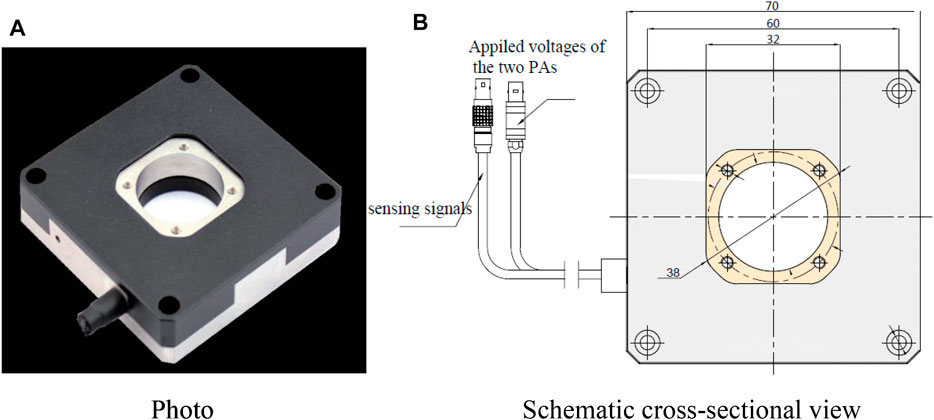
FIGURE 1. Two-axis piezo-scanning mechanism: (A) photo and (B) Schematic cross-sectional view.
2.2 P-I Hysteresis Model of the Mechanism
A discrete play operator in the P-I model of the X-axis is defined as follows:
where r is the input threshold sometimes called the magnitude of the backlash, T is the sampling period, k indicates the sampled time instant, u is the input, x represents the mechanism response, and
By multiplying some such operators
where
Similarly, the P-I model of the Y-axis can be obtained.
3 Hybrid Control Method
Obviously, due to the existence of the hysteresis, the relationship between the output displacement and input voltage of the piezo-scanning mechanism is multi-valued non-linear. In order to improve the accuracy in the motion control, it is necessary to compensate for the hysteresis. Therefore, a feedforward loop is used to compensate and reduce the hysteretic effect, and a feedback control based on a neural network disturbance observer is developed to compensate for the lumped uncertainty due to parametric variations, hysteresis-compensated error, and unmodeled dynamics. The block diagram of the hybrid control is presented in Figure 2.
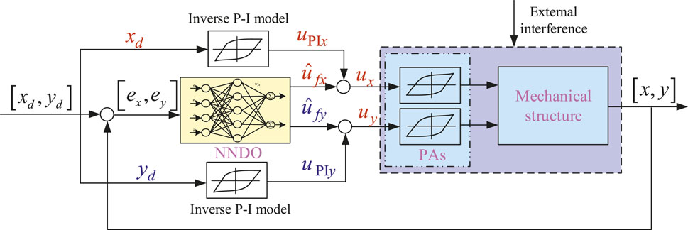
FIGURE 2. Block diagram of the hybrid control.
3.1 Hysteresis Compensator
The inverse P-I hysteresis model of the X-axis can be obtained as follows (Bashash and Jalili, 2008):
where
Similarly, the inverse P-I model of the Y-axis can be obtained.
From the inverse P-I hysteresis model given by Eqs 4–8, the feedforward control can be designed. The schematic representation of the feedforward control is shown in Figure 2.
3.2 Uncertainties Compensator
The uncertainties compensator control is established relying on an uncertainties observer in this section. The uncertainties observer based on the radial basis function neural network (NN) is developed to observe the uncertainties. The radial basis function NN observer is presented in Figure 3. The inputs are
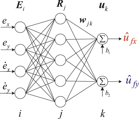
FIGURE 3. Structure of the uncertainties observer.
The output of the input layer is as follows:
where
The output of the hidden layer can be written as follows:
where
The output of the compensator can be given by the following:
where
4 Experiment and Discussion
4.1 Hysteresis Modeling Results
First of all, a harmonic applied voltage is employed to motive the piezo-scanning mechanism. The practical and estimated responses are illustrated in Figure 4. It can be seen from Figure 4 that a good consistence between the practical and estimated result is observed. Good modeling accuracy using the P-I hysteresis model suggests that the proposed model can closely represent the practical hysteresis in PA.
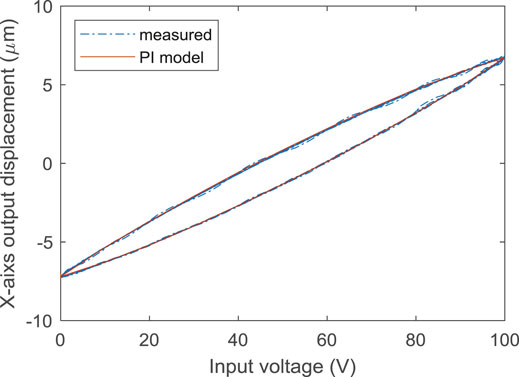
FIGURE 4. Modeling result of the P-I model.
4.2 Hysteresis Compensation Results
Then, the control performance of the hysteresis compensator is verified by experiment. The experimental result is shown in Figure 5. The blue line in Figure 5A represents the original hysteresis curve without the compensator. From Figure 5B, the maximum linearization error is 0.253 μm. The curves between the displacement and input voltage of the PA without the compensator present apparent hysteresis. The relationships between the displacement and applied voltages of the PA with the compensator based on the P-I model are almost linear. That is to say, the hysteresis compensator based on the P-I model has the ability to accurately linearize PA. It should be pointed out that this error is mainly caused by uncertainties including parametric variations, hysteresis-compensated error, and unmodeled dynamics.
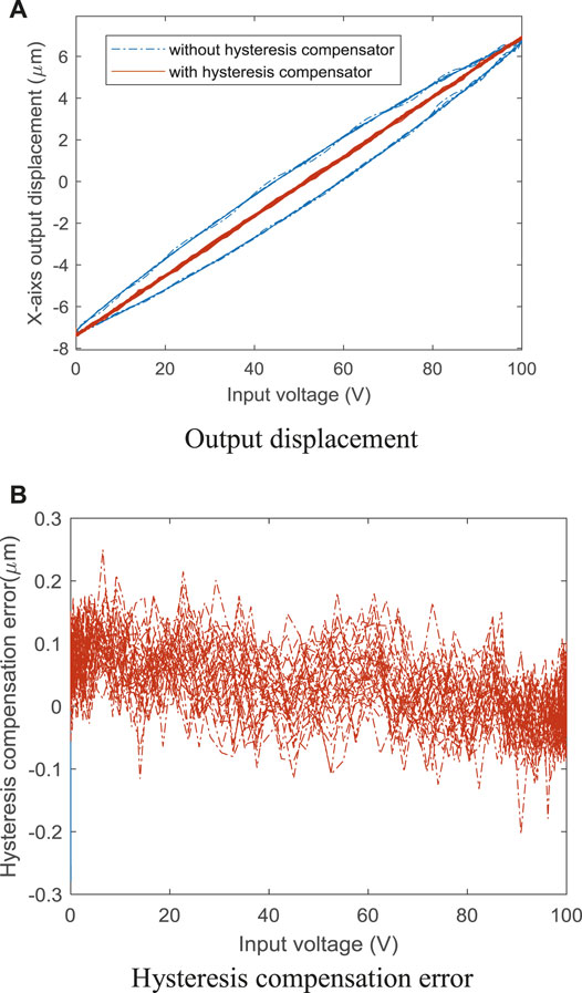
FIGURE 5. Hysteresis compensation result of the inverse P-I model: (A) Output displacement and (B) Hysteresis compensation error.
4.3 Tracking Control Results
Furthermore, to validate the positioning performance of the proposed hybrid control method, a harmonic positioning task is performed. The control result is illustrated in Figure 6, which indicates the proposed hybrid control method can obtain a high positioning accuracy and the maximum absolute control error is 0.124 μm.
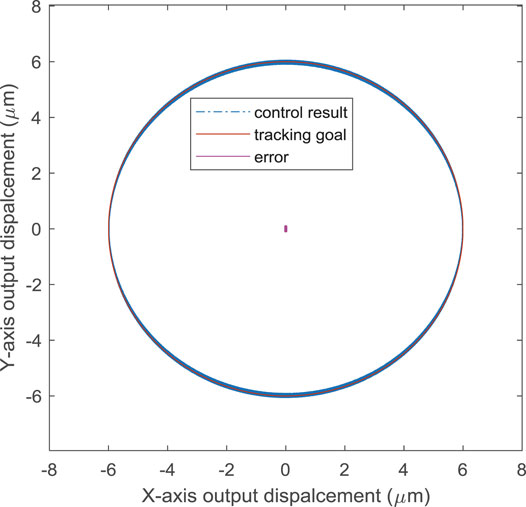
FIGURE 6. Tracking control result of the hybrid control method with the harmonic tracking signal.
Finally, a complex tracking task with varying amplitude and varying frequencies is implemented. The frequency bandwidth of the task is 1–150 Hz as shown in Figure 7A, and the sampling frequency of the displacement sensors is 10 kHz. The tracking control result of the hybrid control method is shown in Figures 7B,C. It can be observed in Figure 7 that the proposed controller can also accurately track the complex trajectory.
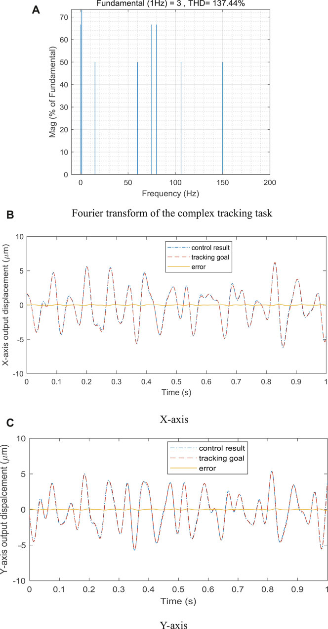
FIGURE 7. Tracking control result of the hybrid control method with the complex tracking task: (A) Fourier transform of the conmplex tracking task, (B) X-axis, and (C) Y-axis.
These validate the proposed control method.
5 Conclusion
In this study, in order to effectively control the two-axis piezo-scanning mechanism, the hybrid controller is proposed and presented. The controller is composed of two compensators. The hysteresis compensator is designed based on the P-I hysteresis model in order to reduce the nonlinear hysteresis effect of PA. The uncertainties compensator based on the neural network disturbance observer is adopted to compensate for uncertainties including parametric variations, hysteresis-compensated error, and unmodeled dynamics. Experimental results show that the proposed hybrid controller can overcome the mentioned nonlinearity and uncertainty efficiently and preserve good positioning accuracy.
Data Availability Statement
The raw data supporting the conclusion of this article will be made available by the authors, without undue reservation.
Author Contributions
HJ, SL, and XH contributed to conception and design of the study. JS organized the database. CS performed the statistical analysis. All authors contributed to manuscript revision and read and approved the submitted version.
Conflict of Interest
The authors declare that the research was conducted in the absence of any commercial or financial relationships that could be construed as a potential conflict of interest.
Publisher’s Note
All claims expressed in this article are solely those of the authors and do not necessarily represent those of their affiliated organizations, or those of the publisher, the editors, and the reviewers. Any product that may be evaluated in this article, or claim that may be made by its manufacturer, is not guaranteed or endorsed by the publisher.
References
Bashash, S., and Jalili, N. (2008). A Polynomial-Based Linear Mapping Strategy for Feedforward Compensation of Hysteresis in Piezoelectric Actuators. ASME J. Dyn. Syst. Meas. Control 130 (3), 031008. doi:10.1115/1.2907372
Cheng, L., Liu, W., Hou, Z.-G., Yu, J., and Tan, M. (2015). Neural-Network-Based Nonlinear Model Predictive Control for Piezoelectric Actuators. IEEE Trans. Ind. Electron. 62, 7717–7727. doi:10.1109/tie.2015.2455026
Faa-Jeng Lin, F. J., Ying-Chih Hung, Y. C., and Syuan-Yi Chen, S. Y. (2009). FPGA-based Computed Force Control System Using Elman Neural Network for Linear Ultrasonic Motor. IEEE Trans. Ind. Electron. 56, 1238–1253. doi:10.1109/tie.2008.2007040
Gu, G.-Y., Zhu, L.-M., Su, C.-Y., Ding, H., and Fatikow, S. (2016). Modeling and Control of Piezo-Actuated Nanopositioning Stages: A Survey. IEEE Trans. Autom. Sci. Eng. 13 (1), 313–332. doi:10.1109/tase.2014.2352364
Huang, S. J., and Chiu, C. M. (2009). Optimal LuGre Friction Model Identification Based on Genetic Algorithm and Sliding Mode Control of a Piezoelectric-Actuating Table. Trans. Inst. Meas. Control 31 (1), 181–203. doi:10.1177/0142331208093938
Ikhouane, F., Mañosa, V., and Rodellar, J. (2007). Dynamic Properties of the Hysteretic Bouc-Wen Model. Syst. Control Lett. 56 (3), 197–205. doi:10.1016/j.sysconle.2006.09.001
Liu, X., Wang, Y., Geng, J., and Chen, Z. (2013). Modeling of Hysteresis in Piezoelectric Actuator Based on Adaptive Filter. Sensors Actuators A Phys. 189, 420–428. doi:10.1016/j.sna.2012.09.013
Mercorelli, P., and Werner, N. (2014). A Hybrid Actuator Modelling and Hysteresis Effect Identification in Camless Internal Combustion Engines Control. Ijmic 21 (3), 253–263. doi:10.1504/ijmic.2014.060729
Mercorelli, P., and Werner, N. (2016). An Adaptive Resonance Regulator Design for Motion Control of Intake Valves in Camless Engine Systems. IEEE Trans. Industrial Electron. 64 (4), 3413–3422. doi:10.1109/TIE.2016.2606091
Quant, M., Elizalde, H., Flores, A., Ramírez, R., Orta, P., and Song, G. (2009). A Comprehensive Model for Piezoceramic Actuators: Modelling, Validation and Application. Smart Mat. Struct. 18 (12), 125011–125026. doi:10.1088/0964-1726/18/12/125011
Sang, W. L., Ahn, K. G., and Ni, J. (2007). Development of a Piezoelectric Multi-axis Stage Based on Stick-And-Clamping Actuation Technology. Smart. Mat. Struct. 16, 2354–2367.
Tang, H., and Li, Y. (2015). Feedforward Nonlinear PID Control of a Novel Micromanipulator Using Preisach Hysteresis Compensator. Robotics Computer-Integrated Manuf. 34, 124–132. doi:10.1016/j.rcim.2014.11.006
Truong, B. N. M., and Ahn, K. K. (2013). Modeling and Control of Hysteresis for DEAP Actuator. Sensors Actuators A Phys. 201, 193–206. doi:10.1016/j.sna.2013.07.004
Wang, Y., Wu, S., Xu, L., and Zeng, Y. (2019). A New Precise Positioning Method for Piezoelectric Scanner of AFM. Ultramicroscopy 196, 67–73. doi:10.1016/j.ultramic.2018.09.016
Yang, H., and Zhu, W. (2020). High-bandwidth Open-Loop Motion Control of a Piezo-Positioning Mechanism Based on a Composite Electromechanical Dynamic Model. Smart Mat. Struct. 29 (10), 107001. doi:10.1088/1361-665x/aba81f
Yangmin Li, S., and Li, Y. (2013). Modeling and High Dynamic Compensating the Rate-dependent Hysteresis of Piezoelectric Actuators via a Novel Modified Inverse Preisach Model. IEEE Trans. Contr. Syst. Technol. 21 (5), 1549–1557. doi:10.1109/tcst.2012.2206029
Zhu, W., and Rui, X.-T. (2016). Hysteresis Modeling and Displacement Control of Piezoelectric Actuators with the Frequency-dependent Behavior Using a Generalized Bouc-Wen Model. Precis. Eng. 43, 299–307. doi:10.1016/j.precisioneng.2015.08.010
Zhu, W., and Rui, X. T. (2017). Modeling of a Three Degrees of Freedom Piezo-Actuated Mechanism. Smart. Mat. Struct. 26 (13pp), 015006. doi:10.1088/0964-1726/26/1/015006
Keywords: piezo-scanning mechanism, neural network, uncertainty observer, hysteresis, compensation control
Citation: Liu S, Jiang H, Huang X, She J, Si C and Lv S (2022) Precision Compensation Control of a Piezo-Scanning Mechanism. Front. Mater. 9:852642. doi: 10.3389/fmats.2022.852642
Received: 11 January 2022; Accepted: 03 June 2022;
Published: 13 July 2022.
Edited by:
Marcelo J. Dapino, The Ohio State University, United StatesReviewed by:
Paolo Mercorelli, Leuphana University Lüneburg, GermanyQuan-Liang Zhao, North China University of Technology, China
Copyright © 2022 Liu, Jiang, Huang, She, Si and Lv. This is an open-access article distributed under the terms of the Creative Commons Attribution License (CC BY). The use, distribution or reproduction in other forums is permitted, provided the original author(s) and the copyright owner(s) are credited and that the original publication in this journal is cited, in accordance with accepted academic practice. No use, distribution or reproduction is permitted which does not comply with these terms.
*Correspondence: Huhai Jiang, amlhbmdodWhhaUB5YW5kZXguY29t