 Pei Xu
 Sijie Wang1,2
 Dengfu Chen
 Huamei Duan
94% of researchers rate our articles as excellent or good
Learn more about the work of our research integrity team to safeguard the quality of each article we publish.
Find out more
ORIGINAL RESEARCH article
Front. Mater., 06 April 2022
Sec. Structural Materials
Volume 9 - 2022 | https://doi.org/10.3389/fmats.2022.841961
This article is part of the Research TopicFluxes and Steel QualityView all 5 articles
The thicknesses of mold flux film and air gap are significant factors that affect the high-efficiency heat transfer, the strand lubrication and mold taper design of billet ultra-high speed continuous casting mold. Therefore, this paper established the three-dimensional fluid flow, heat transfer and solidification model, interfacial heat transfer model and two-dimensional stress-strain model to conduct multiphysics modeling. Thereby the thickness distributions of liquid slag, solid slag and air gap in the ultra-high speed billet continuous casting mold were obtained, and analyzing the effects of melting temperature of mold flux and mold taper. The results indicate that the thicknesses of liquid slag and solid slag increase and decrease respectively along the casting direction, and air gap mainly concentrates near the mold corner. The maximum thicknesses of liquid slag, air gap, and solid slag at the mold outlet are respectively 0.18 mm at the center of the strand surface (x = 0 mm), 0.28 mm at the strand corner (x = 80 mm) and 0.67 mm at x = 74 mm. The lower melting temperature of mold flux, the greater the liquid slag thicknesses and ascend from 0.14 to 0.18 mm, and conversely the maximum air gap thicknesses descend from 0.31 to 0.28 mm and existing ranges also get smaller, which is more favorable for the strand lubrication. To eliminate the air gap, the appropriate linear mold taper is 0.45% m−1 at the 6.5 m/min in casting speed.
Nowadays, ultra-high speed continuous casting (UHSCC) has become one of the important tendencies in the development of billet continuous casting, and (Yang et al., 2020) has shown that it is the guarantee for further decreasing cost, improving efficiency and continuous casting and rolling. However, the casting speed of conventional billet continuous casting production is about 3 to 4 m/min, while ultra-high casting speed can reach 6.5 m/min or even higher. For realizing the UHSCC, the high-efficiency heat transfer of the mold must be ensured, because (Brimacombe and Sorimachi, 1977) and (Mahapatra et al., 1991) have illustrated that surface and subsurface cracks, longitudinal cracks and even breakout are directly related to it, and then will affect the production of the high-quality strand. Among several factors influencing the high-efficiency heat transfer, the thickness distributions of mold flux film and air gap between the solidified strand and mold copper plate are fairly significant to fulfil the strong and uniform cooling of molten steel, well lubrication of the strand in the mold and mold taper design etc. Nevertheless, there is a relative lack of investigation about this aspect in the billet continuous casting, especially for the UHSCC.
Based on the facts that (Yang et al., 2020) investigated the flowing behavior of mold flux under different casting speed (Mills, 2016a), and (Mills, 2016b) analyzed the structures and properties of different mold fluxes used in continuous casting, and (Niu et al., 2021) designed the mold taper of slab mold, it is found that the thickness distributions of mold flux film and air gap in the mold are not only affected by casting speed, physical properties of mold flux and mold taper and so on, and but also involve the thermal-mechanical behaviors of the strand and mold. However, owing to harsh environment and shorting advanced detective means, the distributions of mold flux film and air gap in the mold can hardly be obtain by real-time measurement. As a result, numerical simulation has become the predominant method used to study these phenomena. In the earlier stage, for investigating easily the heat transfer and solidification behavior of molten steel as well as the mechanical behavior of the solidified shell in the mold, researchers treated simply mold flux film and air gap in different ways (Jing and Cai, 2000). directly ignored the role of mold flux and analyzed the distribution of temperature, heat flow and air gap during the solidification through the thermal-mechanical coupling (Wang and He, 2001). did not consider the distribution of mold flux as well, and then chose the empirical heat flux calculation formula as the boundary condition and loaded it on the surface of the strand and hot face of mold to study the effect of mold taper on strain of the solidified shell. While (Schwerdtfeger et al., 1998) adopted a constant heat transfer coefficient to replace the function of mold flux to describe the heat transfer between the solidified strand and mold copper plate. Obviously, these ways in which the existence of mold flux film is ignored directly or equivalently substituted are inconsistent with the real condition.
In order to consider the impact of mold flux film on heat transfer (Han et al., 1999), regarded it as a fixed thickness to conduct the thermal-mechanical coupling simulation of the solidification process of molten steel in the slab mold. Nevertheless, Investigations on slag infiltration, which (Zhang and Wang, 2017) and (Ji et al., 2021) had conducted, have shown that the thicknesses of liquid slag and solid slag present the changing situation along the casting direction, and so the abovementioned research still exists limitation (Meng and Thomas, 2003). had gained the changing distribution of mold flux film along the casting direction via established the interfacial heat transfer model based on the conservation of mass and momentum in the mold flux channel between the strand and mold copper plate, and then used it to carry out the simulation of heat transfer and solidification of molten steel and mold taper design etc. In this model, the thickness of mold flux film only varies at the casting direction, while along the circumferential direction of the mold it is still regarded as uniform distribution. However, in the actual continuous casting process, the temperature and contraction of the strand in the mold are dynamic, and the resulting distributions of mold flux film in the circumferential and casting two directions are also varying. In addition, these models do not all distinguish liquid slag and solid slag formed during the solidification process of mold flux, and meanwhile the air gap caused by the contraction of the solidified shell is not considered as well in detail.
Therefore, for obtaining accurately the thickness distributions of liquid slag, solid slag and air gap in the mold, lots of thermal-mechanical models were developed (Saraswat et al., 2007). predicted the thickness variations of liquid slag layer, solid slag layer and air gap in 120 mm × 120 mm billet mold based on the established two-dimensional (2D) stress-strain slice model of the solidified shell (Cai and Zhu, 2011a). used the similar model to obtain the shrinkage of the solidified shell and the thicknesses of liquid slag, solid slag and air gap in the slab mold. While through the established three-dimensional (3D) stress-strain model (Niu et al., 2019), fully considered the effect of the shrinkage of the solidified shell along the casting direction, determined the thickness distributions of liquid slag, solid slag and air gap in the slab mold, and analyzed the influence of narrow surface mold taper on the thickness of air gap. Although abovementioned models can determine the thickness distributions of different slag layers and air gap, they all exist the deficiency, namely, the way of treating the effect of the turbulent flowing in liquid region of the strand on the heat transfer is debatable. These models all choose to enlarge the thermal conductivity of liquid steel by 7–43 (Saraswat et al., 2007) times to consider the heat transfer enhancement effect caused by turbulent flowing. However, due to excessive large range of the amplifying times, the parameter’s selection is empirical and uncertain, especially for the UHSCC, and then this will affect the final results. To solve this problem (Xie et al., 2017), and (Yu et al., 2017) established the 3D fluid flow, heat transfer and solidification model to calculate the temperature distribution of the strand with considering the turbulent flowing, and then extracted the slice temperature and loaded it into the 2D stress-strain model to conduct multiphysics modeling. This research’s shortcomings are that when calculating the comprehensive thermal resistance between the solidified strand and mold copper plate, the radiation heat transfer through mold flux and air gap was not considered carefully, and it did not give out the distributions of mold flux film and air gap.
Based on the abovementioned analyses, it is known that the existing researches on the distributions of mold flux film and air gap between the solidified strand and mold copper plate are mainly focused on the slab and little involves the billet. Moreover, the detailed reports on the thickness distributions of liquid slag, solid slag and air gap in billet UHSCC mold are hardly found. Thus, aiming at the 160 mm × 160 mm cross-section billet, this paper established the 3D fluid flow, heat transfer and solidification model to consider the effect of turbulent flowing on heat transfer, the interfacial heat transfer model between the solidified strand and copper plate in which the radiation heat transfer is considered in detail, and the 2D stress-strain model of the strand. On the base of these models, the thickness distributions of liquid slag, solid slag and air gap in the billet UHSCC mold were gained via multiphysics modeling, and the effects of melting temperature of mold flux and mold taper were also analyzed. This is of great significance for realizing high-efficiency heat transfer in the UHSCC mold, well lubrication of the strand in the mold and mold taper design.
As shown in Figure 1, the multiphysics modeling, which consists of the 3D fluid flow, heat transfer and solidification model, the interfacial heat transfer model and the 2D stress-strain model, were conducted by the sequential coupling method. The detailed procedures are as follows.
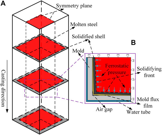
FIGURE 1. Schematic diagram of multiphysics modeling in billet mold, (A) computational domain of mold, (B) 1/4 transverse section of slice model.
Firstly, according to the initial conditions, the 3D fluid flow, heat transfer and solidification model was used to simulate and obtain the temperature distribution of the solidified strand in the mold. Secondly, along the casting direction of the strand, several temperature slices were extracted and loaded sequentially into the 2D stress-strain model of the solidified shell as the thermal load. Subsequently, the mathematical simulation of thermal-mechanical coupling was carried out to get the shrinkage of the solidified shell. Thirdly, based on the temperature and heat flow obtained in the first step and the shrinkage at the second step, the thickness distributions of liquid slag
(1) The molten steel and water are assumed to be the incompressible Newtonian fluid.
(2) The arc structure and oscillation of mold are neglected.
(3) The mold coating is neglected due to its low thickness.
(4) According to the symmetry, the 1/4 model is chosen.
Figures 2A,B show the 3D fluid flow, heat transfer and solidification geometry model of billet mold, which includes molten steel, mold copper tube and cooling water, and the relevant parameters of mold are listed in Table 1 in the Figure 2A, for avoiding the interference of backflow formed at the mold outlet, the part of molten steel was extended by 1,000 mm. Subsequently, as shown in Figure 2C, the geometry model was meshed by ANSYS ICEM, and the hexahedral grid was selected. During meshing, the maximum mesh size of molten steel was set 4 mm in the mold, and its extension section was 5 mm. In addition, along the circumferential direction of the billet, the local grid size of the 10 mm thickness that is away from the strand surface was refined to 1 mm. While mesh sizes of mold copper tube and cooling water were set 2 and 1 mm respectively. The total number of meshes is about 1 million.
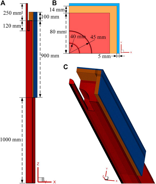
FIGURE 2. Geometry model and computational grid of billet mold. (A) front view, (B) top view, (C) meshing.
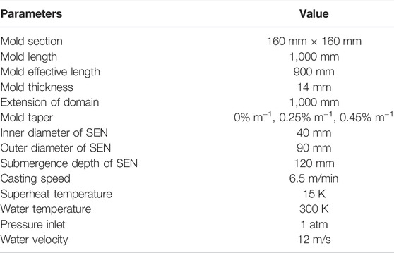
TABLE 1. Parameters of billet mold.
The materials involved in this model include molten steel, copper, water, mold flux and air. The thermal-physical parameters of copper tube and cooling water adopted the data from the study of (Cai and Zhu, 2011b). And the parameters of mold flux, air gap and Q235 steel (Cwt, % = 0.15) were listed in Table 2.
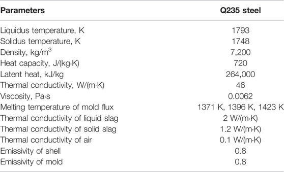
TABLE 2. Material physical properties.
In the 3D mathematical model, the transient flow, heat transfer and solidification of molten steel in billet need to be simulated. Therefore, the governing equations mainly contains continuity equation, momentum equation, standard k-ε equation and energy equation. The detailed description could be found in the works of (Wu et al., 2020) and (Chen et al., 2018).
For boundary conditions of mathematical simulation, the inlet of molten steel was set up to velocity-inlet and its velocity could be calculated via mass conversation, and the temperature of inlet was pouring temperature 1808 K. Similarly, the velocity and temperature of cooling water at the inlet were respectively 12 m/min and 300 K. The abovementioned both at the outlet were set up as pressure-outlet used by (Chaudhary et al., 2008). The surface of molten steel in the billet mold was set up to the specified shear and thermal isolation. The both interfaces of molten steel/hot face of mold copper tube as well as cold face of mold copper tube/cooling water were set up to the coupled interface. Subsequently, the comprehensive thermal resistance, which contains the effects of mold flux film and air gap, was loaded into the coupled interface through UDF, and this resistance could be solved in Section 2.2.
The commercial software Fluent 19.2 was adopted in this paper. In the process of numerical simulation, its solution method was set up to SIMPLEC, the time step size was 0.01 s, and the number of time steps was 6,000, namely, the total calculation time was 60 s. With the exception of satisfying the relevant residuals, the convergence standards still included that the both outlet temperatures of molten steel and cooling water must keep stable.
The heat transfer between the solidified strand and mold copper tube in the billet continuous casting mold is considerably complicated. In the upper part of mold where the surface temperature of the strand is larger than the melting temperature of mold flux, consequently, the gap caused by the shrinkage of the solidified shell will be filled with liquid slag and solid slag. As the strand moves downwards along the casting direction, its overall temperature also decreases continually. When the surface temperature of the strand is lower than the melting temperature of mold flux, the liquid slag will disappear and absolutely turn into the solid slag. As a result, the gap cannot be filled with mold flux, and the resulting air gap will start to appear and become large gradually. Accordingly, the interfacial heat transfer modes between the solidified shell and mold can be divided into two types, as shown in Figure 3.
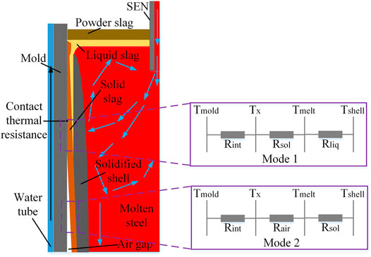
FIGURE 3. Schematic diagram of interfacial heat transfer modes in billet mold.
Based on the abovementioned analysis, the corresponding interfacial heat transfer model was established, and some assumptions were given out for simplifying the computation.
(1) The difference between glassy slag phase and crystal slag phase was not considered, and both of them were regarded as the solid slag.
(2) Ignoring the slight solidification deformation of mold flux, and treating it as the interface thermal resistance.
(3) The status and distribution of mold flux are affected by the surface temperatures of the strand and copper tube’s hot face, itself melting temperature and the gap thickness between the solidified strand and mold copper tube.
(4) The liquid slag has a well fluidity, as a result, the gap between the solidified shell and mold will be full mold flux as long as liquid slag exists. Conversely, the air gap will appear at the location where liquid slag disappears.
(Zappulla et al., 2020) and (Wang et al., 2016) thought that the behavior of heat transfer from the solidified strand to mold copper tube consists of two parallel contributions, heat conduction and radiation. Therefore, the corresponding heat flux could be solved by Eq. 4.
The comprehensive thermal resistance R in the coupling interface between the solidified strand and hot face of mold copper tube is:
The heat transfer coefficient of radiation, hrad, is as follows.
Where, the Stefan-Boltzmann,
The heat transfer coefficient of heat conduction,
Where, Rint is the interfacial thermal resistance between mold tube’s hot face and solid slag or air, and can be gotten by Eq. 8 introduced by (Yamauchi et al., 2002). dliq, dsol, and dair are the thicknesses of liquid slag, solid slag and air gap, respectively, m, which can be solved via Eqs. 9–11. kliq, ksol, and kair are the corresponding thermal conductivities, W/(m⋅K).
Where, q is the interfacial heat flux between the solidified shell and mold, and obtained in Section 2.1, W/m2. Tmelt is the melting temperature of mold flux, K. dgap is the shrinkage gap between the solidified shell and mold copper tube, m, and calculated by the stress-strain model in Section 2.3. The specific parameters for mold flux and air were listed in Table 2.
In this model, the initial thickness of solid slag adopted 0.15 mm provided by (Yamauchi et al., 2002). Moreover, according to the formula that (Saraswat et al., 2007) has explained, the initial thickness of liquid slag thickness in this paper was 0.04 mm. While the initial surface temperatures of the strand and copper tube’s hot face were 1273 and 500 K, respectively.
In Section 2.2, it can be seen that the thicknesses of liquid slag, solid slag and air gap depends on the shrinkage gap, dgap. Thus, this paper set up a 2D stress-strain slice model, which consists of the solidified shell and mold copper tube, was set up to conduct the thermal-mechanical simulation, as shown in Figure 1B. Moreover, in order to deal with the complexity of thermal-mechanical coupling in this model, the following assumptions have been given out.
(1) In the 2D model, plane strain was chosen to carry out the thermal-mechanical simulation.
(2) Ignoring the mold deformation, consequently, mold copper tube and the solidified shell were set up to the rigid and deformable body, respectively.
(3) The friction between the solidified strand and mold copper tube was not considered.
(Zappulla et al., 2020) have illustrated that the total strain rate due to heat transfer, solidification and contraction of the solidified shell can be divided into three parts in the actual continuous casting mold, as shown in Eq. 12.
Where,
The stress and strain rates are described by the constitutive Eq. 13.
Where, “:” represents the inner product of tensors.
Where,
The thermal strain caused by volume change owing to temperature change and phase transformation is shown in Eq. 15.
Where,
Inelastic strain contains rate-independent plastic strain and time-dependent creep. Creep is very important in the process of high temperature solidification, but it cannot be distinguished from the plastic strain, as described by (Li and Thomas, 2004). Herein, the inelastic strain rate was defined by a unified formula, namely, a single internal variable that (Anand, 1982) had proposed, and equivalent inelastic strain
Where,
The Q235 steel used in this paper was assumed to be isotropic hardening. Therefore, von Mises loading surface, relevant plasticity and the normal assumption in Prandtl-Reuss flow law were adopted. Thus, the inelastic strain rate could be calculated by Eq. 19.
The strand in the model mainly suffer the combined action of thermal stress and ferrostatic pressure, and the corresponding boundary conditions and loads are as follows.
(1) The initial temperature was the pouring temperature 1808 K, and was set up to the predefined field of initial analysis step.
(2) Along the casting direction of the strand, several temperature slices, which were obtained in Section 2.1, were extracted and set sequentially up to the predefined field of each analysis step.
(3) The ferrostatic pressure was loaded on the solidification front via the user-subroutine in the way of uniform distribution along the circumferential direction of the strand, and it could be calculated by Eq. 20. In this paper, the solid fraction of 0.85 was selected as the solidification front, as explained by (Liu et al., 2013).
Where, P is the ferrostatic pressure, Pa.
(4) The normal interaction between the solidified strand and mold copper tube was set up to “hard” contact, as a result, both of them could be separated after solidification and shrinkage of the strand.
(5) The detailed boundary conditions of the strand and copper tube are as follows.
X-axis direction’s symmetry face of the strand is U2 = UR1 = UR3 = 0.
Y-axis direction’s symmetry face of the strand is U1 = UR2 = UR3 = 0.
Reference point of mold copper tube is U1 = U2 = U3 = UR1 = UR2 = UR3 = 0.Where, U1, U2, and U3 are the displacements along the x, y, and z axis, respectively. UR1, UR2 and UR3 are the radians of rotation around the x, y, and z axis, respectively.
The computational results of the model were affected significantly by the high-temperature mechanical properties of steel grade. In this paper, the relevant parameters of Q235 (C(wt, %) = 0.15) mainly were obtained by the trial measurements. To some higher temperature that the experimental condition cannot achieve, such as mushy zone or even higher, the corresponding data could be gotten though the empirical formulas in the literatures.
Figure 4 shows the elastic modulus E and Poisson’s ratio
Where, fS is the solid fraction. fZST is the solid fraction at zero strength temperature, and fZST = 0.8, as used by (Xie et al., 2017). ES and EZST the elastic modulus at the solidus temperature and zero strength temperature, MPa, and EZST = 1 MPa.
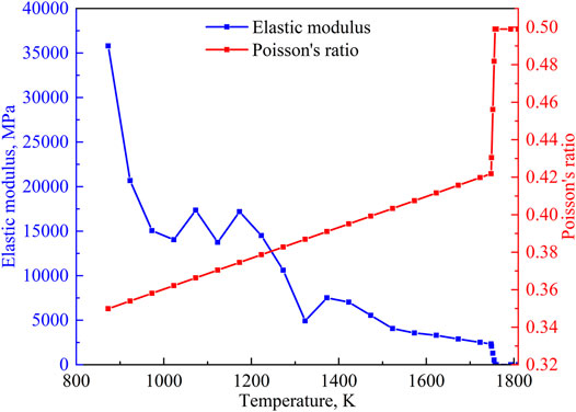
FIGURE 4. Elastic modulus and Poisson’s ratio of Q235 at different temperatures.
The Poission’s ratio in solid region was calculated via the regression Eq. 22 proposed by (Uehara, 1983). In the mushy zone, Eq. 23 was adopted. Above the liquidus temperature, Poission’s ratio approached 0.5 according to the generalized Hook’s Law, and choosing 0.499 in this paper.
Where,
The curves of thermal expansion coefficient
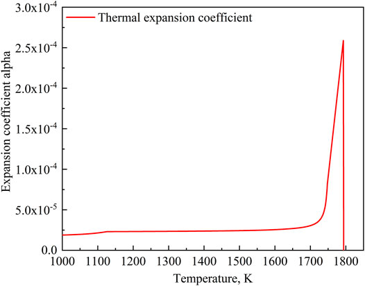
FIGURE 5. Expansion coefficient alpha of Q235 at different temperatures.
Eq. 24 describes the thermal linear expansion of material.
Where,
The thermal strain of material is solved by Eq. 25 in the commercial software ABAQUS.
Where, Tref is the reference temperature, K, namely, the temperature corresponding to solid fraction of 0.85 in this paper. T0 is the initial temperature, K.
The engineering stress-strain curves at different temperatures were measured by high-temperature tensile tests. Subsequently, the data applicable to ABAQUS in Figure 6 was calculated by Eqs. 27–29. When the temperature is higher than the solidus, setting up the yield stress to 0.01 MPa to eliminate the stress in the liquid phase and mushy zone.
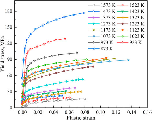
FIGURE 6. Relationships between yield stress and plastic strain of Q235 at different temperatures.
The 2D stress-strain slice model of the solidified shell in the billet continuous casting mold was solved by the commercial software ABAQUS 6.14. The slice was meshed by adopting the tetrahedral structured grid, and total grids are 6,400. While the element type was set up to CPE4RH (standard, linear, hybrid formulation and reduced integration) in the process of finite element simulation. Moreover, 11 analysis steps were established to realize the movement of the strand from the meniscus of mold to its outlet. For the solution method, the static and general was chosen with the nonlinear effect of large deformation or displacement.
Owing to the lack of relevant data of the billet UHSCC at present, it is very difficult to verify directly the accuracy of model at the casting speed of 6.5 m/min. Therefore, in this paper, the results of 3.0 m/min casting speed that were computed via using the abovementioned multiphysics were compared with the known data at the conventional casting speed in the literatures to achieve the model verification. Through the model of this paper, the thickness of the solidified shell and temperature of mold copper tube at the 3.0 m/min in casting speed were obtained, and then compared with the existing literatures’ data and measured values under the similar working conditions. The detailed are as follows.
Figure 7 displays the comparison of thicknesses of the solidified shell along the central line of the strand surface, which consists of several kinds of results from model prediction, the literatures, calculated by square root formula and measured. It can be seen that the shell thickness of model prediction in the upper part of mold is in good agreement with the results of (Saraswat et al., 2007). The square root formula on the solidification of molten steel has been widely used to predict the solidified shell’s thickness in the continuous casting. For the solidification coefficient of billet (Bernhard et al., 2013), chose 16–22 mm/min0.5. In order to ensure the shell thickness as much as possible and avoid the breakouts, the coefficient of 22 mm/min0.5 was chosen to calculate the shell thickness, and then compared with the model prediction’s. Results indicates that both of tendencies are similar, at the initial stage of mold, molten steel solidifies rapidly, and then the solidification rate gradually slows down along the casting direction, finally, both get consistent at the mold outlet. In addition, the shell thickness at the mold outlet obtained by measuring the breakout strand of a certain steel plant was compared and verified with model prediction’s, and the difference is less than 0.5 mm, which meets the requirements.
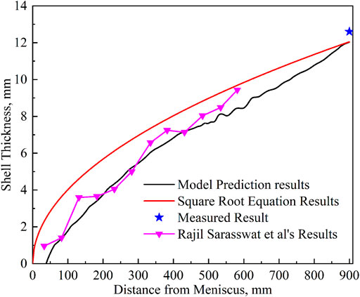
FIGURE 7. Comparison of shell thickness between model prediction and literatures.
The temperatures at the hot and cold faces of the mold copper tube which are respectively from model prediction and the literatures were plotted into Figure 8. In Figure 8A, the changing tendency of temperature of mold copper tube’s hot face calculated by the model is the same as the results of (Chow et al., 2013). Beginning from the meniscus, the temperature firstly increases and then decreases along the casting direction, and both of them exist a maximum temperature about 50 mm below the meniscus. Moreover, at the part of 50–700 mm below the meniscus of mold, the temperature’s variation of hot face is in consistent with the results of (Saraswat et al., 2007), and both decrease slowly. About the comparison results of temperature of the cold face in Figure 8B, the results of model prediction are agreement with Pinherio et al.’s. While below the 200 mm from meniscus of the mold, the calculated temperatures of cold face are consistent with the results of (Wu et al., 2020), especially near the mold outlet, both of them exist the temperature recovery phenomenon.
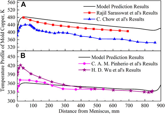
FIGURE 8. Temperature comparison of mold copper plate, (A) hot face, (B) cold face.
In the abovementioned comparisons, although the specific data are not completely same due to the difference of the cross-sections and casting speeds between the literatures and this paper, the overall variation tendencies are consistent well. Therefore, this indirectly verifies the accuracy of the model in this paper, and it is feasible to determine the thicknesses of liquid slag, solid slag and air gap through the model.
The thickness distributions of liquid slag, solid slag and air gap in the billet mold under the UHSCC of 6.5 m/min calculated by the above method were plotted into Figure 9, when melting temperature of mold flux is 1371 K and mold taper is 0% m−1. In this paper, casting direction is regarded as z-coordinate, and z = 0 mm and z = 900 mm represents respectively the meniscus and outlet of mold. While transverse direction of the1/4 strand is the x-coordinate, and x = 0 mm and x = 80 mm represent respectively the center and corner of the strand surface. As shown in Figure 9A, the initial thickness of liquid slag is about 0.25–0.27 mm, and then it presents a descending tendency along the casting direction, and the liquid slag’s thickness at the outlet of mold is 0.18 mm at x = 0 mm. Along the transverse direction of the strand, the liquid slag’s thickness decreases slowly from x = 0 mm to x = 62 mm. While in the range of x = 62 mm to x = 80 mm, due to the 2D cooling near the mold corner, the surface temperature of the strand declines rapidly to the melting temperature of mold flux, and thereby cause that the liquid slag’s thickness gets thin sharply until it disappears. At x = 80 mm, the position where the liquid slag disappear is at z = 416 mm. In addition, at the about x = 78 mm and along the casting direction. it can be found that the thickness of liquid slag firstly gets continually small and becomes 0 mm at z = 530 mm, subsequently, it reappears at z = 760 mm and increases gradually to about 0.037 mm at the mold outlet. This is because the thermal resistance gets large when the existence of air gap at the corner, and the resulting heat transfer from the solidified shell to mold copper tube becomes weak. As a result, the surface temperature of the strand will rise again above the melting temperature of mold flux, and furtherly resulting in the remelting of solid slag to form the liquid slag.
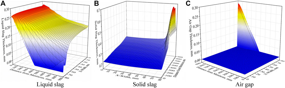
FIGURE 9. Thickness distributions of mold flux film and air gap at casting speed of 6.5 m/min. (A) liquid slag, (B) solid slag, (C) air gap.
Contrary to the variation of the liquid slag’s thickness, along the casting direction the solid slag’s increases from 0.22 to 0.31 mm at x = 0 mm, as shown in Figure 9B. While at the transverse direction of the strand, at first, the thickness of solid slag rises slowly and then increases sharply the peak value of 0.67 mm at x = 74 mm, subsequently, begins to decrease rapidly near the corner. This is mainly because closer to the mold corner is and the higher cooling strength is, and the resulting solid slag continuously become thick and its growth rate is also lager and lager, when the liquid slag exists. However, due to the premature disappearance of liquid slag caused by the excessive cooling near the corner, the resulting solid slag will stop growing, together with its remelting, and then leading the solid slag’s thickness decrease. According to the thickness distribution of air gap in Figure 9C, it mainly exists near the corner. Along the casting direction, the air gap starts to appear at x = 80 mm and z = 420 mm and then gradually increases, and then achieves the maximum value of 0.28 mm at the outlet of mold. While along the transverse direction, the air gap near the mold outlet earliest appears at x = 78 mm.
The melting temperature of mold flux is an important factor affecting the solidification of liquid slag in the continuous casting mold, as described by (Kamaraj et al., 2020), which plays a conclusive role in the thickness distributions of liquid slag, solid slag and air gap. For illustrating the effect of melting temperature at the UHSCC of 6.5 m/min, three kinds of mold fluxes with melting temperatures of 1371 K, 1396 and 1423 K were investigated in this paper. Based on the aim of more intuitively and quantitatively analyzing the results, several typical positions with x = 0 mm, x = 80 mm and the maximum thickness of solid slag were selected, and then extracting the corresponding thicknesses were extracted and plotted into Figures 10, 11.
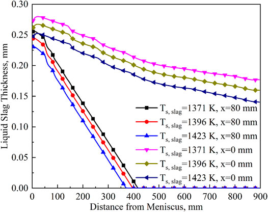
FIGURE 10. Thicknesses of liquid slag at typical positions with different melting temperatures of mold flux.
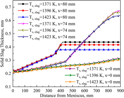
FIGURE 11. Thicknesses of solid slag at typical positions with different melting temperatures of mold flux.
For the thickness distributions of liquid slag in Figure 10, at x = 0 mm, the initial thicknesses of three sorts of mold fluxes with melting temperatures of 1371 K, 1396 and 1423 K are 0.27, 0.26, and 0.25 mm respectively, and then gradually decrease along the casting direction and their downward trends are almost the same. When reaching the mold outlet, the liquid slag’s thicknesses of the three kinds of mold fluxes are 0.18, 0.16 ,and 0.14 mm, and it is because the solidification time of liquid slag is advanced with the increase of melting temperature. In addition, although the overall variation tendencies of three sorts of liquid slag’s thicknesses are similar, as the melting temperature goes up, the corresponding thicknesses of liquid slag become thin, as a result, it will affect the lubrication of the strand in the billet mold. Therefore, the mold flux with low melting temperature is recommended to ensure the well lubrication of the strand in the UHSCC mold. At x = 80 mm (mold corner), the initial liquid’s slag thicknesses are 0.26, 0.24, and 0.23 mm, respectively, and then ascending gradually along the casting direction. However, different from the x = 0 mm, firstly, the liquid slag’s thicknesses decrease faster, secondly, they will disappear at a certain mold height, and resulting in the deterioration of lubrication environment of the strand near the corner of mold. The liquid slag with melting temperatures of 1371 K, 1396, and 1423 K disappears at z = 396 mm, z = 368 mm, and z = 336 mm respectively, and this indicates that the higher the solidification temperature is, the earlier the liquid slag disappears.
In the Figure 11, the initial thicknesses of three sorts of mold flux at several typical positions all are about 0.22 mm, and then increases along the casting direction. For the part of about z = 0–340 mm, the upward tendencies of solid slag’s thicknesses at three typical positions are x = 80 mm > x = 70 mm > x = 0 mm, which is mainly because the closer to the mold corner, the higher the cooling efficiency, consequently, the mold flux is easier to solidify. For the z = 340–900 mm, the solid slag’s thicknesses of three sorts of mold fluxes with melting temperatures of 1371, 1396, and 1423 K cannot become continuously thick due to the disappearance of liquid slag at x = 80 mm, and will keep constant until the mold outlet where the thicknesses are 0.44, 0.42, and 0.39 mm, respectively. At x = 74 mm, because of the forever existence of liquid slag and the stronger cooling effect near the mold corner, the thicknesses of solid slag rises quickly. In addition, the thicknesses of three kinds of mold fluxes along the casting direction are basically the same, there is difference only near the mold outlet, namely, their thicknesses are 0.67, 0.66, and 0.64 mm, respectively, which descends with the increase of melting temperature. It is because the liquid slag’s thickness is thicker and the heat transfer is stronger at the low melting temperature, consequently, the strand temperature near the mold outlet will be lower and the liquid slag will solidify faster. Moreover, the corresponding shrinkage of the solidified shell will also increase at this time, which is more conducive to the growth of solid slag. For x = 0 mm, the thicknesses of the three kinds of mold fluxes all rise gradually along the casting direction, and all reaches about 0.31 mm at the mold outlet.
The analysis has shown that the air gap is mainly concentrated in the corner area at the UHSCC of 6.5 m/min. Thus, for more intuitively observing the thickness changing of air gap, some characteristic positions’ data will be extracted and plotted into Figure 12. It can be found that the air gap does not exist in the earlier stage of casting direction. When the liquid slag disappears as well as cannot continue to fill the gap formed by the shrinkage of the solidified shell, the air gap just begins to appear, and then increase continually to the mold outlet, meanwhile, the maximum air gap thicknesses of the three kinds of mold fluxes are 0.28, 0.29, and 0.31 mm respectively at x = 80 mm.
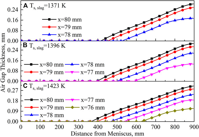
FIGURE 12. Thicknesses of air gap at typical positions with different melting temperatures of mold flux. (A) 1371 K, (B) 1396 K, (C) 1423 K.
On the other hand, the ascending of the melting temperature will widen the existence range of air gap in the transverse direction of the strand. The corresponding ranges are about x = 78–80 mm at 1371 K, x = 77–80 mm at 1396 K and x = 76–80 mm at 1423 K. These indicate that increasing the melting temperature of mold flux will not only add the air gap thickness, but also broaden its existing range, which is unfavorable to the strong and uniform cooling of the strand in the UHSCC mold.
The air gap formed between the solidified strand and mold copper tube has a considerable impact on the heat transfer behavior in the mold, while mold taper is the most effective method to eliminate it. Therefore, this paper chose three sorts of linear mold tapers of 0%, 0.25%, and 0.45% m−1 to study their effect on the thicknesses of air gap at the casting speed of 6.5 m/min. Based on these, the data of mold corner where the air gap is maximum was collected and plotted into Figure 13. In the Figure 13, as the linear mold taper increases from 0% m−1 to 0.45% m−1 at casting speed of 6.5 m/min, the earliest appearance positions of air gap move downwards from z = 420 mm to the mold outlet, and the air gap’s thicknesses of mold corner get thin from 0.28 to 0.0 mm. Thus, to avoid the appearance of air gap in the billet mold, especially for the UHSCC required the high-efficiency heat transfer, the recommended linear mold taper range is 0.45% m−1 at the casting speeds of 6.5 m/min.
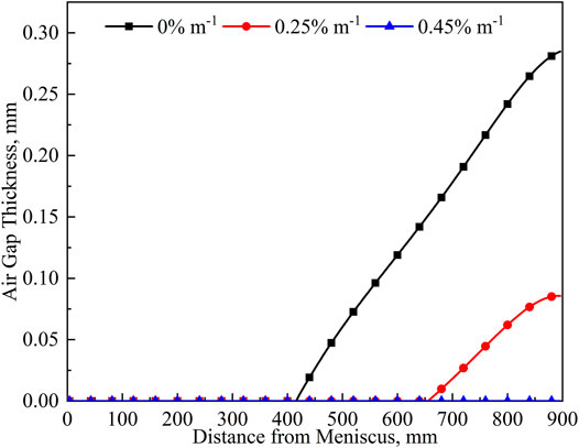
FIGURE 13. Air gap thicknesses of mold corner with different mold tapers at four casting speeds.
(1) Under the UHSCC of 6.5 m/min, the overall changing tendencies of the thicknesses of liquid slag and solid slag along the casting direction gradually decrease and increase, respectively. Near the mold corner, the liquid slag will disappear at z = 530 mm and then reappear at z = 760 mm, while the solid slag exists the maximum value of 0.67 mm at the mold outlet. The air gap of the mold corner starts at z = 420 mm and then gradually increases to 0.28 mm.
(2) When the melting temperature of mold flux ascends from 1371 to 1423 K, the liquid slag thicknesses of mold outlet at x = 0 mm decrease from 0.18 to 0.14 mm, and their disappearance positions are, respectively, z = 396 mm, z = 368 mm and z = 336 mm at x = 80 mm. Thus, the low melting temperature of mold flux is more conducive to the lubrication of the strand in the UHSCC mold. At x = 80, the solid slag thicknesses firstly increase to 0.44, 0.42, and 0.39 mm, and then remaining constant. While its maximum thicknesses are 0.67, 0.66, and 0.64 mm at x = 74 mm and mold outlet, respectively. At x = 0 mm, three solid slag’s thicknesses all increase gradually to 0.31 mm. For the air gap, it will become thick along the casting direction and its existence range becomes wider, and the maximum thicknesses of mold outlet are 0.28, 0.29, and 0.31 mm at x = 80 mm, respectively.
(3) That increasing the mold taper can decrease the air gap’s thickness obviously. To eliminate the effect of air gap, the suitable linear mold taper is 0.45% m−1 at the UHSCC of 6.5 m/min.
The raw data supporting the conclusions of this article will be made available by the authors, without undue reservation.
PX: Conceptualization, Methodology, Software, Formal analysis, Investigation, Data curation, Writing-original draft, Visualization. SW: Data curation, Visualization. YZ: Software, Formal analysis. DC: Supervision, Funding acquisition. ML: Supervision. HD: Supervision.
This work was financially supported by the National Natural Science Foundation of China (NSFC) (grant number 51874060).
The authors declare that the research was conducted in the absence of any commercial or financial relationships that could be construed as a potential conflict of interest.
All claims expressed in this article are solely those of the authors and do not necessarily represent those of their affiliated organizations, or those of the publisher, the editors, and the reviewers. Any product that may be evaluated in this article, or claim that may be made by its manufacturer, is not guaranteed or endorsed by the publisher.
Anand, L. (1982). Constitutive Equations for the Rate-dependent Deformation of Metals at Elevated Temperatures. J. Eng. Mater. Technol. 104, 12–17. doi:10.1115/1.3225028
Bernhard, C., Hiebler, H., and Wolf, M. M. (2013). How Fast Can We Cast? Ironmaking & Steelmaking 27, 450–454. doi:10.1179/030192300677778
Brimacombe, J. K., and Sorimachi, K. (1977). Crack Formation in the Continuous Casting of Steel. Mtb 8, 489–505. doi:10.1007/bf02696937
Cai, Z. Z., and Zhu, M. Y. (2011b). Simulation of thermal Behavior during Steel Solidification in Slab Continuous Casting Mold II. Model Verification and Results Analysis. Acta Metall. Sin 47, 678–687. doi:10.3724/SP.J.1037.2010.00664
Cai, Z. Z., and Zhu, M. Y. (2011a). Simulation of thermal Behavior during Steel Solidification in Slab Continuous Casting Mold I. Mathematical Model. Acta Metall. Sin 47, 671–677. doi:10.3724/SP.J.1037.2010.00663
Chaudhary, R., Lee, G.-G., Thomas, B. G., and Kim, S.-H. (2008). Transient Mold Fluid Flow with Well- and Mountain-Bottom Nozzles in Continuous Casting of Steel. Metall. Materi Trans. B 39, 870–884. doi:10.1007/s11663-008-9192-0
Chen, H., Long, M., Chen, D., Liu, T., and Duan, H. (2018). Numerical Study on the Characteristics of Solute Distribution and the Formation of Centerline Segregation in Continuous Casting (CC) Slab. Int. J. Heat Mass Transfer 126, 843–853. doi:10.1016/j.ijheatmasstransfer.2018.05.081
Chow, C., Samarasekera, I. V., Walker, B. N., and Lockhart, G. (2013). High Speed Continuous Casting of Steel Billets: Part 2: Mould Heat Transfer and Mould Design. Ironmaking & Steelmaking 29, 61–69. doi:10.1179/030192302225001947
Friedman, E. (1975). Thermomechanical Analysis of the Welding Process Using the Finite Element Method. J. Press. Vessel Technol 97, 206–213. doi:10.1115/1.3454296
Han, H. N., Lee, J.-E., Yeo, T.-j., Won, Y. M., Kim, K.-h., Oh, K. H., et al. (1999). A Finite Element Model for 2-dimensional Slice of Cast Strand. ISIJ Int. 39, 445–454. doi:10.2355/isijinternational.39.445
Ji, J., Cui, Y., Zhang, X., Wang, Q., He, S., and Wang, Q. (2021). Influence of Interfacial Thermal Resistance on Initial Solidification and Heat Transfer in Continuous Casting Mold of Steel. Steel Research Int. 92, 2000636. doi:10.1002/srin.202000636
Jing, D. J., and Cai, K. K. (2000). Finete Element Simulation of Thermo-Mechanically Coupled States in Continuous Casting Mold. Acta Metall. Sin 36, 403–406. doi:10.3321/j.issn:0412-1961.2000.04.015
Kamaraj, A., Dash, A., Murugaiyan, P., and Misra, S. (2020). Investigation on Mold Flux Melting and Consumption during Continuous Casting of Liquid Steel. Metall. Mater. Trans. B 51, 2159–2170. doi:10.1007/s11663-020-01906-9
Koric, S., and Thomas, B. G. (2008). Thermo-mechanical Models of Steel Solidification Based on Two Elastic Visco-Plastic Constitutive Laws. J. Mater. Process. Technol. 197, 408–418. doi:10.1016/j.jmatprotec.2007.06.060
Li, C., and Thomas, B. G. (2004). Thermomechanical Finite-Element Model of Shell Behavior in Continuous Casting of Steel. Metall. Materi Trans. B 35, 1151–1172. doi:10.1007/s11663-004-0071-z
Liu, K., Chang, Y.-h., Han, Z.-g., and Zhang, J.-q. (2013). Effect of Asynchronous Adjustments of Clamping Cylinders on Triangular Crack of Slab Castings under Application of Soft Reduction. J. Iron Steel Res. Int. 20, 38–47. doi:10.1016/s1006-706x(13)60054-0
Mahapatra, R. B., Brimacombe, J. K., and Samarasekera, I. V. (1991). Mold Behavior and its Influence on Quality in the Continuous Casting of Steel Slabs: Part II. Mold Heat Transfer, Mold Flux Behavior, Formation of Oscillation marks, Longitudinal Off-Corner Depressions, and Subsurface Cracks. Mtb 22, 875–888. doi:10.1007/bf02651164
Meng, Y., and Thomas, B. G. (2003). Heat-transfer and Solidification Model of Continuous Slab Casting: CON1D. Metall. Materi Trans. B 34, 685–705. doi:10.1007/s11663-003-0040-y
Mills, K. C. (2016a). Structure and Properties of Slags Used in the Continuous Casting of Steel: Part 1 Conventional Mould Powders. ISIJ Int. 56, 1–13. doi:10.2355/isijinternational.isijint-2015-231
Mills, K. C. (2016b). Structure and Properties of Slags Used in the Continuous Casting of Steel: Part 2 Specialist Mould Powders. ISIJ Int. 56, 14–23. doi:10.2355/isijinternational.isijint-2015-355
Niu, Z., Cai, Z., and Zhu, M. (2019). Dynamic Distributions of Mold Flux and Air Gap in Slab Continuous Casting Mold. ISIJ Int. 59, 283–292. doi:10.2355/isijinternational.isijint-2018-609
Niu, Z., Cai, Z., and Zhu, M. (2021). Effect of Mold Cavity Design on the Thermomechanical Behavior of Solidifying Shell during Microalloyed Steel Slab Continuous Casting. Metall. Mater. Trans. B 52, 1556–1573. doi:10.1007/s11663-021-02123-8
Saraswat, R., Maijer, D. M., Lee, P. D., and Mills, K. C. (2007). The Effect of Mould Flux Properties on Thermo-Mechanical Behaviour during Billet Continuous Casting. ISIJ Int. 47, 95–104. doi:10.2355/isijinternational.47.95
Schwerdtfeger, K., Sato, M., and Tacke, K.-H. (1998). Stress Formation in Solidifying Bodies. Solidification in a Round Continuous Casting Mold. Metall. Materi Trans. B 29, 1057–1068. doi:10.1007/s11663-998-0075-1
Tszeng, T. C., and Kobayashi, S. (1989). Stress Analysis in Solidification Processes: Application to Continuous Casting. Int. J. Machine Tools Manufacture 29, 121–140. doi:10.1016/0890-6955(89)90060-6
Uehara, M. (1983). Mathematical-modeling of the Unbending of Continuously Cast Steel Slabs. Vancouver: The University of British Columbia.
Wang, E.-G., and He, J.-C. (2001). Finite Element Numerical Simulation on Thermo-Mechanical Behavior of Steel Billet in Continuous Casting Mold. Sci. Technology Adv. Mater. 2, 257–263. doi:10.1016/s1468-6996(01)00066-3
Wang, X., Kong, L., Du, F., Yao, M., Zhang, X., Ma, H., et al. (2016). Mathematical Modeling of Thermal Resistances of Mold Flux and Air Gap in Continuous Casting Mold Based on an Inverse Problem. ISIJ Int. 56, 803–811. doi:10.2355/isijinternational.isijint-2015-601
Wu, H., Chen, J., and Peng, Z. (2020). Simulation of the Flow-Heat Transfer Process in Billet Mold and Analysis of the Billet Rhomboidity Phenomenon. Appl. Therm. Eng. 173, 115235. doi:10.1016/j.applthermaleng.2020.115235
Xie, X., Yu, S., Long, M., Chen, D., Duan, H., Chen, H., et al. (2017). Fluid Flow and Heat Transfer Behavior of Liquid Steel in Slab Mold with Different Corner Structures. Part 1: Mathematical Model and Verification. Numer. Heat Transfer, A: Appl. 72, 642–656. doi:10.1080/10407782.2017.1394137
Yamauchi, A., Emi, T., and Seetharaman, S. (2002). A Mathematical Model for Prediction of Thickness of Mould Flux Film in Continuous Casting Mould. ISIJ Int. 42, 1084–1093. doi:10.2355/isijinternational.42.1084
Yang, J., Chen, D., Long, M., and Duan, H. (2020). Transient Flow and Mold Flux Behavior during Ultra-high Speed Continuous Casting of Billet. J. Mater. Res. Technology 9, 3984–3993. doi:10.1016/j.jmrt.2020.02.025
Yu, S., Xie, X., Chen, D., Chen, H., Long, M., Duan, H., et al. (2017). Fluid Flow and Heat Transfer Behavior of Liquid Steel in Slab Mold with Different Corner Structures. Part 2: Fluid Flow, Heat Transfer, and Solidification Characteristics. Numer. Heat Transfer, Part A: Appl. 72, 657–668. doi:10.1080/10407782.2017.1394138
Zappulla, M. L. S., Cho, S.-M., Koric, S., Lee, H.-J., Kim, S.-H., and Thomas, B. G. (2020). Multiphysics Modeling of Continuous Casting of Stainless Steel. J. Mater. Process. Technology 278, 116469. doi:10.1016/j.jmatprotec.2019.116469
Keywords: fluid flow, heat transfer, thermal-mechanical coupling, air gap, mold flux film, ultra-high speed continuous casting
Citation: Xu P, Wang S, Zhou Y, Chen D, Long M and Duan H (2022) Thickness Distributions of Mold Flux Film and Air Gap in Billet Ultra-High Speed Continuous Casting Mold Through Multiphysics Modeling. Front. Mater. 9:841961. doi: 10.3389/fmats.2022.841961
Received: 23 December 2021; Accepted: 01 March 2022;
Published: 06 April 2022.
Edited by:
Qifeng Shu, University of Oulu, FinlandReviewed by:
Ying Ren, Univetsity of science and technology Beijing, ChinaCopyright © 2022 Xu, Wang, Zhou, Chen, Long and Duan. This is an open-access article distributed under the terms of the Creative Commons Attribution License (CC BY). The use, distribution or reproduction in other forums is permitted, provided the original author(s) and the copyright owner(s) are credited and that the original publication in this journal is cited, in accordance with accepted academic practice. No use, distribution or reproduction is permitted which does not comply with these terms.
*Correspondence: Dengfu Chen, Y2hlbmRmdUBjcXUuZWR1LmNu; Mujun Long, bG9uZ211anVuQGNxdS5lZHUuY24=
Disclaimer: All claims expressed in this article are solely those of the authors and do not necessarily represent those of their affiliated organizations, or those of the publisher, the editors and the reviewers. Any product that may be evaluated in this article or claim that may be made by its manufacturer is not guaranteed or endorsed by the publisher.
Research integrity at Frontiers
Learn more about the work of our research integrity team to safeguard the quality of each article we publish.