 Guangai Wu
 Zhiqiang Wu1
 Xiaowei Cheng
- 1CNOOC Research Institute Co., Ltd., Beijing, China
- 2School of New Energy and Materials, Southwest Petroleum University, Chengdu, China
Under conditions of heavy oil thermal recovery, cement sheaths often suffer high-temperature performance degradation and CO2 corrosion. The performance of Class G oil well cement commonly used for cementing, deteriorates significantly at high temperatures and in CO2 environments, which can easily cause accidents. By contrast aluminate cement (CAC), at the same time, has good high-temperature resistance and corrosion resistance. Therefore, this study explored the mechanical properties and permeability of CAC with a high-temperature stabiliser cement slurry system (C1), pure CAC slurry system (C2) and Portland cement with sand cement slurry system (C3) before and after corrosion at 50, 300, 400, 500, and 600°C. The micromorphology, hydration products and pore structure of the cement paste before and after corrosion were analyzed using scanning electron microscopy, X-ray diffraction, thermogravimetry and nitrogen adsorption specific surface area and pore diameter analysis; additionally, the hydration mechanism of CAC under high temperatures and in CO2 environments was explored. The results show that the degree of degradation of the mechanical properties of C1 cement slurry system at high temperatures and under CO2 corrosive environments is significantly lower than that of the C3 cement slurry system. At a curing high temperature of 400°C, the maximum strength of the C1 cement paste reached 36.39 ± 0.37 MPa. The addition of a high-temperature stabiliser improved the mechanical properties of CAC at low temperatures, reduced the formation of C3ASH4 in the cement paste at high temperatures, and improved the strength of the cement paste after high-temperature curing. Compared with the C3 cement slurry system, the C1 cement slurry system had better high-temperature resistance and corrosion resistance and was more suitable for application under conditions of a burning reservoir in heavy oil thermal recovery.
1 Introduction
With the deepening of oil and gas exploration and development to complex strata, some special oil reservoirs have attracted increasing attention from the petroleum industry, among which the exploitation of heavy oil has become an interesting topic in recent years (Yue et al., 2013). At present, the recovery methods for heavy oil primarily include steam driving and oil layer burning (Pang et al., 2018; Strelets and Ilyin, 2021). Burning oil layer is the first thermal oil recovery technology used to develop heavy oil (Askarova et al., 2020). Compared with other heavy oil development technologies, this method has unique high-temperature operation characteristics. A series of chemical reactions occur during crude oil heating and combustion, which are generally divided into thermal cracking, low-temperature oxidation and high-temperature oxidation. During combustion reservoir development, the temperature of the combustion front in the reservoir can reach 500°C; the main chemical reaction in such conditions is high-temperature oxidation, and the main products are CO2, CO and H2O (Pahlavan and Rafiqul, 1995; Jain et al., 2010). CO2 gas produced after high-temperature oxidation is extremely corrosive in the presence of H2O in the oil layer. However, under the combined action of high temperature and CO2 corrosion, the strength of ordinary Portland cement may decrease, its permeability may increase, and its integrity may be damaged (Abid et al., 2015; Achang and Radonjic, 2021). The CO2 corrosion in oil well cement is mainly caused by the dissolution of CO2 gas present in the oil layer in water, formation of corrosive carbonic acid (H2CO3), and chain reaction between bicarbonate (HCO3−) and the hydration product of cement paste formed at high temperatures to form calcium carbonate (CaCO3) crystals (Zhang et al., 2021a; Zhang et al., 2021b). Thus, the original structure of the cement paste is destroyed, leading to the failure of the cement sheath isolation.
At present, domestic and foreign scholars studied cementing slurry systems suitable for heavy oil thermal recovery, mainly in the following two directions: one is the optimization of the chemical composition of cement to increase the relative content of high-temperature resistant hydration products in cement hydration products (Dener et al., 2021; Yang et al., 2021; Frías et al., 2022); the other is the introduction of materials with high strength and high thermal conductivity at high temperatures to optimize the internal microstructure of cement paste (Jiang et al., 2021a; Jiang et al., 2021b; Zhang et al., 2021c). However, most of the existing studies focused on addressing the problem of strength decline at high temperatures, but ignored the damage to the cement sheath caused by CO2 corrosion. It was found that compared with ordinary Class G oil-well cement, aluminate cement (CAC) has better high-temperature resistance, with rapid early strength development, less strength declines at high temperatures, and better corrosion resistance (Cheng et al., 2019; He et al., 2020). Therefore, it is crucial to explore the interaction mechanism between CAC and CO2 at high temperatures.
In this study, the mechanical properties and permeability of three cement slurry systems, CAC slurry system, CAC with high-temperature stabiliser cement slurry system, and Portland cement with sand cement slurry system, were studied at 50, 300, 400, 500, and 600°C before and after corrosion. The scanning electron microscopy (SEM) was used to analyze the microstructure of cement pastes before and after corrosion, The X-ray diffraction analysis (XRD), thermogravimetry analysis (TG/DTG) and nitrogen adsorption specific surface area and pore size analyzer (BJH) were used to analyze the hydration products and pore structure of the cement before and after corrosion. The mechanism of CO2 corrosion of CAC and the hydration mechanism were explored by mechanical and microscopic analysis.
2 Experimental Methods
2.1 Reagents and Materials
Cements used in this study were Class G high sulfate resistant oil-well cement produced by Sichuan Jiahua Special Cement Co., Ltd. Leshan, China and CAC produced by Zhengzhou Great Wall Special Aluminate Co., Ltd. Zhengzhou, China. The chemical compositions of the Class G oil-well cement and CAC are shown in Tables 1, 2.

TABLE 1. Chemical composition of Class G oil well cement.

TABLE 2. Chemical composition of CAC.
The admixtures were high-temperature stabiliser (HS-KZS) produced by Sichuan Hongsheng Petroleum Technology Co., Ltd. Chengdu, China, fluid loss reducer (G33S), retarder, and dispersant (SXY-2) produced by Henan Weihui Chemical Co., Ltd. Weihui, China. The quartz sand was provided by OMAX Petroleum Technology Co., Ltd. Chengdu, China, and its particle size is shown in Figure 1. The median particle size D50 of quartz sand is 193.88 μm.
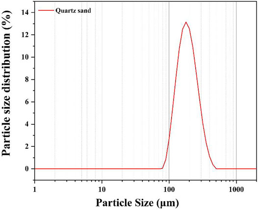
FIGURE 1. Particle size distribution chart of quartz sand.
The chemical composition and micromorphology of HS-KZS are shown in Figure 2 and Table 3, respectively. Table 3 shows that the content of CaO in the high-temperature stabiliser is up to 35%. CaO is an alkaline oxide with high activity. The Al2O3 content is 14.51%, which can form minerals such as aluminate or calcium aluminosilicate. The high-temperature stabiliser contains more SiO2, approximately 34%. The high SiO2 content leads to the formation of low activity and low calcium minerals, which can adjust the hydration products of cement and improve the strength of cement paste (Quercia et al., 2014; Tobón et al., 2015; El-Gamal et al., 2018).
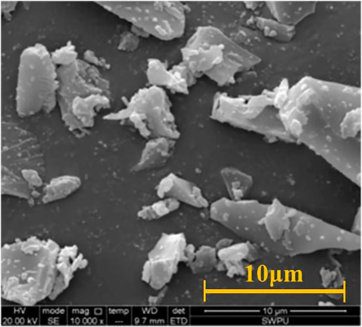
FIGURE 2. Microstructure of high-temperature stabiliser.

TABLE 3. Chemical composition of high temperature stabilizer.
Figure 2 presents the micromorphology of the high-temperature stabilizer, and shows that the high-temperature stabiliser is an irregular block with relatively small surface-attached particles. This structure improves the particle gradation of cement particles to a certain extent, reduces the gap between cement particles, increases the density of cement paste, and improves the strength of cement paste after setting and hardening.
2.2 Experimental Methods
Three different cement slurry systems C1, C2, and C3 were prepared according to the specifications for oil-well cement materials and experiments recommended by API RP 10 B (American Petroleum Institute, 2013). The cement slurry formula is shown in Table 4, and the water-cement ratio of the prepared cement slurry is 0.44. The prepared slurry was poured into the corresponding mould and cured in a constant-temperature water bath at 50°C for 7 days. Then, some of the samples were removed from the water bath and cured in a tubular resistance furnace at 300, 400,500, and 600°C in a CO2 atmosphere for 7 days. The heating regime was 25–70°C, for 60 min, 70–90°C, for 60 min, 90–100°C, for 15 min, followed by heating to the target temperature, which could prevent the damage to the cement paste sample during heating.

TABLE 4. Formula of cement slurry (mass fraction %).
The compressive strength test was conducted in accordance with the GB/T 19139-2012 Chinese national standard oil-well cement test method (China National Standard GB/T 1939-2012 Oil Well Cement Test Method, 2012). The prepared slurry was cured in a cube mold (50.8 mm × 50.8 mm × 50.8 mm) to a predetermined age. Then, the TY-300 pressure testing machine (China Wuxi, Jianyi) with a loading rate of 71.7 kN/min ± 7.2 kN/min was used to test. The tensile strength test was carried out in accordance with the Brazilian split tensile test method (Suchorzewski et al., 2018), and the split tensile strength of the columnar (Φ50.8 mm × 25.4 mm) cement paste was tested using at TY-300 compression testing machine.
The DX-2700 X-ray diffractometer (Dandong Fangyuan Instrument Co., Ltd. Dandong, China) was used to study the phase change of cement paste before and after corrosion. The test conditions were as follows: scanning step length of 0.04°, each step time of 1s, and the diffraction angle range of 5–80°. The permeability of the cement paste was tested using a DSK quasi-III core porosity and permeability joint tester (Changzhou Yiyong Technology Co., Ltd. Changzhou, China), and the permeability and porosity of the cement pastes were analyzed under different temperatures and CO2 gas atmospheres. A ZEISS EVO MA15 scanning electron microscope (Carl Zeiss, Germany) was used to observe the microscopic morphology of the high-temperature stabiliser and the cross-sectional morphology of the cement paste samples. The dried cement pastes were knocked into small thin sheet samples, and then the block sample was glued to the sample base with conductive adhesive. The fresh section of the sample was sprayed with gold by ion sputtering and then placed under a scanning electron microscope for observation. The working voltage was 5 kV and the transmitting current was 10 μA. The heat loss of the selected cement pastes was tested using a TGA/SDTA851/e thermal analyser (Mettle Toledo, Switzerland). The heating rate was 10°C/min, the temperature range was 25–600°C, and the atmosphere was 60 ml/min nitrogen. The dried cement paste sample was broken, and then the cement paste sample was ground with a mortar into fine power. The sample was then placed into the instrument and the parameters for testing were set.
3 Results and Discussion
3.1 The Properties of Cement Slurry
Table 5 shows the engineering properties of different cement slurry systems. Table 5 shows that the density of the C1 cement slurry is 1.85 g/cm3, C2 cement slurry is 1.84 g/cm3, and C3 cement slurry is 1.91 g/cm3. The fluidity of the C1 cement slurry is 24.1 cm, C2 cement slurry is 18.2 cm, C3 cement slurry is 26 cm. The density and fluidity of the C3 cement slurry is the relatively high, and the flow behavior index of C3 cement slurry is 0.98, the consistency coefficient is 0.078, which indicates that the addition of sand had great influence on the engineering properties of cement slurry. However, the addition of the high-temperature stabiliser had little influence on the density but greater on the fluidity, the flow behavior index and the consistency coefficient. In the early stage of cement hydration, the high-temperature stabiliser particles were distributed on the surface of the cement particles and wrapped the surface of the cement particles, which played a role in delaying the mutual overlap of the initial hydration products of the cement. In addition, it had a blocking effect on the contact between cement particles and water, which slowed down the hydration process of cement, and increased the fluidity of cement slurry to a certain extent, but increased the viscosity of cement paste.

TABLE 5. Engineering properties of cement slurry.
3.2 Compressive Strength and Tensile Strength
Figure 3 shows the compressive strengths of the three cement slurry systems—C1, C2, and C3 cured at different temperatures. The figure shows that at the curing temperature of 50°C, the minimum compressive strength of C2 cement paste is 13.69 ± 0.69 MPa, which is 31% lower than that of C3 cement paste and 35% lower than that of C1 cement paste. This is because CAC hydration is considerably affected by temperature (Ukrainczyk and Matusinović, 2010; Klaus et al., 2013), and the strength development is unstable at low temperatures. Meanwhile, the C1 cement slurry contains high-temperature stabiliser, which promotes the hydration of cement, and its filling effect also improves the compressive strength of the cement paste. In addition, CAC cement paste is prone to strength shrinkage when cured for 7 days (Fernández-Jiménez et al., 2011), and the addition of a high-temperature stabiliser in C1 can inhibit this phenomenon; therefore, its strength is higher than that of C2. The compressive strength of the cement pastes at various temperature points at high temperatures is C1 > C2 > C3. At the curing temperature of 400°C, the maximum strength of C1 cement paste is 36.39 ± 0.37 MPa, while the compressive strength of C2 cement paste without a high-temperature stabiliser was only 25.29 ± 0.51 MPa, indicating that the addition of a high-temperature stabiliser can effectively inhibit the strength decline of CAC cement paste at high temperatures. The compressive strength of the C3 cement paste is relatively low at all temperature points, which indicates that high temperature and CO2 significantly impact the mechanical properties of the C3 cement paste. Portland cement is more susceptible to corrosion and damage than CAC, although sand addition has a certain inhibitory effect on its high-temperature strength decline.
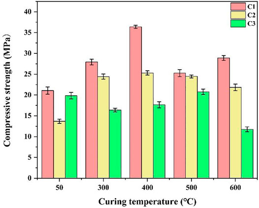
FIGURE 3. Compressive strength of cement paste cured at different temperatures.
Figure 4 presents the tensile strengths of the C1, C2, and C3 cement pastes cured for 7 days at different temperatures and gas environments. Figure 4 shows that the tensile strengths of the three cement pastes decrease with the increase in curing temperature, and the tensile strengths of the cement pastes C1 > C2 > C3 at each temperature point. Owning to the addition of a high-temperature stabiliser, the tensile strength of the cement paste is relatively high at low and high temperatures, and its tensile strength decreases less at high temperatures and CO2 environments, resulting in the maintenance of good mechanical properties. The tensile strength of the C3 cement decreases rapidly under high temperatures and CO2 environments until it completely loses its strength. This indicates that the integrity of the C3 cement is seriously damaged by high temperatures and corrosion.
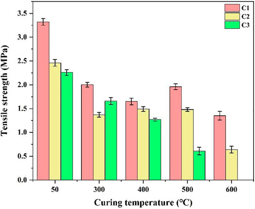
FIGURE 4. Tensile strength of the cement paste cured at different temperatures.
Based on the above analysis, CAC has higher stability than Class G oil-well cement under high temperature and CO2 corrosion, especially after the addition of high-temperature stabiliser to CAC; the mechanical properties of the cement pastes, however, are relatively stable.
3.3 Porosity and Permeability
The pore structure of cement paste has a certain impact on its mechanical properties. Therefore, this study explored the porosity and permeability of the C1 and C3 cement paste systems after curing in different environments. Figure 5 shows the porosity distributions of C1 and C3 at different temperatures. Figure 6 suggests that the porosity of C1 is significantly lower than that of C3 cement at 50°C. However, at the curing temperatures of 300, 400, 500, and 600°C and under CO2 atmosphere, the porosity of the C1 cement increases significantly and exceeds that of the C3 cement. Notably, at the curing temperatures of 400°C, and higher, the porosity of the C1 cement paste remains stable with the increaser in temperature, while the porosity of the C3 cement paste shows a growing trend with the rise of temperature. The increase in porosity of the C1 cement paste was caused by the temperature increase, evaporation of free water in the cement paste, and volume shrinkage caused by the crystal transformation of the hydration products.
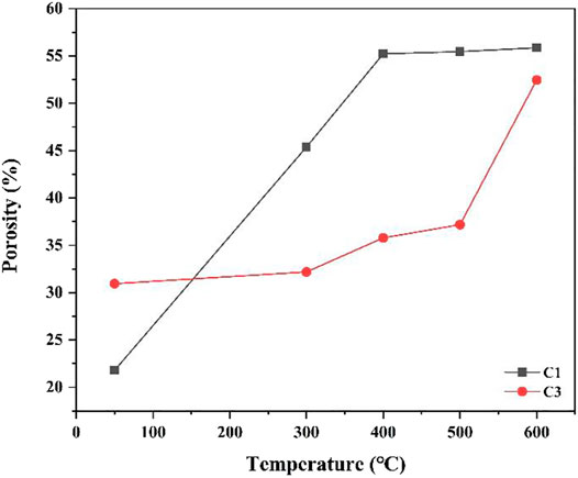
FIGURE 5. Porosity diagram of C1 and C3 cement pastes after curing at different temperatures.
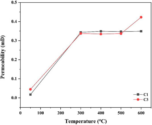
FIGURE 6. Permeability of C1 and C3 cement pastes at different temperatures.
Figure 6 presents the permeability curves of the C1 and C3 cement slurry systems after curing at different temperatures. Figure 6 shows that the permeability of C3 is higher than that of C1 when cured at 50°C. At the curing temperature increases to 300°C, the permeability of the C1 cement paste remains unchanged, but the permeability of C3 increases. This indicates that after a partial water loss, the porosity of C3 cement may be increased owning to corrosion, which increases permeability. A comparison of the permeabilities of the C1 and C3 cement pastes, shows that the C1 cement slurry system has stronger resistance to high temperatures and CO2 environments, and its performance is better than that of the C3 cement slurry system.
Based on the above analysis, the C1 cement slurry system has better stability than the C3 cement slurry system under high temperature and CO2 environments. However, although C1 has high strength, its porosity and permeability are also relatively high. Therefore, it is necessary to explore the pore size distribution of the cement pastes.
3.4 Pore Size Distribution
In this study, the pore size distributions of the C1 cement paste cured at 50 and 600°C in a CO2 atmosphere were investigated. Figure 7 shows the pore size distribution curves of the C1 cement paste cured at 50 and 600°C in a CO2 atmosphere. Figure 8A that the pore size of the C1 cement paste is mainly distributed in the range of 0–10 nm, and there are no lager pores, which is also the reason for the higher compressive strength and tensile strength of the C1 cement paste. Comparison of the C1 cement paste cured at 50 and 600°C shows that the volume change rate of the C1 cement paste cured at 600°C is higher than that of the C1 cement paste cured at 50°C, and the cumulative pore volume of the C1 cement paste cured at 600°C is also higher than that of the C1 cement cured at 50°C. Results of the tensile strength test suggest that the increase of macropores in the cement paste pore structure decreases tensile strength. Meanwhile, when combined with the results of porosity analysis they show that the increase in curing temperature mainly causes the evaporation of free water inside the cement pastes and the transformation and shrinkage of C2ASH8, C2AS and other phases (Wu et al., 2021).
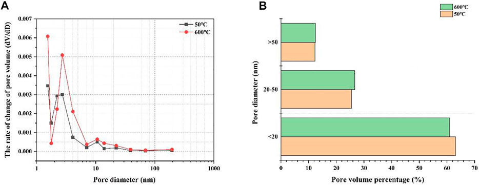
FIGURE 7. Pore size distribution curve (A) and histogram (B) of C1 cement paste after curing at 50 and 600°C.
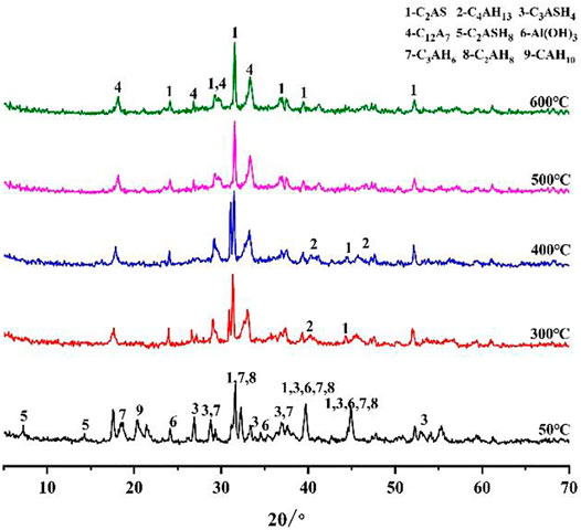
FIGURE 8. XRD diffraction patterns of C1 cement paste under different curing environments.
Based on the results of porosity analysis, permeability and pore size distribution changes, although C1 cement pastes have higher porosity and permeability, their internal pores are small. Studies have shown that in cement pastes, pores with a diameter of less than 20 nm are harmless, 20–50 nm pores are less harmful, and pores greater than 50 nm are harmful (Zhang et al., 2020). Figure 7B shows that the percentage of harmless pores in the cement paste after curing at 600°C is lower than in that cured at 50°C, while the percentage of harmful pores are almost equal, implying that the mechanical properties of the two should be similar from the pore structure perspective. In addition, the phase composition and microstructure of cement pastes also have a certain impact on the mechanical properties of cement pastes. Therefore, the phase composition and micromorphology of cement pastes at different temperatures are discussed in the following sections.
3.5 Phase Composition
In this section, the phase changes of the C1 and C3 cement slurry systems at different temperatures (50, 300, 400, 500 and 600°C) in a CO2 environment after curing for 7 days are explored. Figure 8 shows the XRD diffraction pattern of the C1 cement paste. Figure 8 shows that the C1 cement paste cured at 50°C is mainly composed of C2ASH8, C3AH6, C2AH8 and Al(OH)3 phases (Mostafa et al., 2012). C2ASH8 is stabilized by the aggregation of Al(OH)3 and C-S-H gel-containing rock, which is beneficial to the strength of C1 cement at low temperatures. With an increase in temperature, C2AH8 and CAH10 in C1 cement paste undergo phase transformation into C3AH6 (Hidalgo et al., 2009; Chavda et al., 2015), which has a relatively stable crystal phase and is one of the main strength sources of CAC (Mostafa et al., 2012). However, in this process, the porosity and permeability of the cement paste became larger, which leads to a certain reduction in the strength of cement pastes (Ukrainczyk and Matusinović, 2010). At 300 °C in a CO2 environment, the hydration product C2ASH8 in the C1 cement paste decomposed into C2AS. At the same time, Al(OH)3 was dehydrated and decomposed to into Al2O3. With the increase in C2AS in the C1 cement paste, the strength of the cement paste increased to a certain extent. At the temperature of 500°C, part of C2AS decomposed into C12A7, which is still beneficial to the strength of the C1 cement. At the curing temperature of 600°C, the main phases of C1 cement were C2AS and C12A7 (Lee et al., 2017). Therefore, the cement pastes maintained a high compressive strength and tensile strength, which is consistent with the changes in the mechanical properties obtained in the previous test.
Figure 9 shows the XRD patterns of the C3 cement slurry system after curing for 7 days at different temperatures (50, 300, 400, 500, and 600 °C) in a CO2 atmosphere. Figure 9 shows that the main phases of C3 cement cured at 50°C are CH, SiO2, C-S-H and CaCO3 (Chen et al., 2021; Chen et al., 2022). A large amount of SiO2 is contained in the cement owning to the addition of quartz sand to C3. At the curing temperature of 300°C, the diffraction peak intensity of CH increases, indicating that its content increases. At 400°C, CH begins to decompose or be corrode, and the diffraction peak of CaCO3 also appears in the XRD diffraction pattern. At the curing temperatures of 500 and 600°C, only the diffraction peaks of SiO2 and CaCO3 remain in the XRD patterns of the C3 cement, and these two phases do not have cementation. Therefore, the structure of the C3 cement paste becomes loose, which leads to a significant decrease in strength.
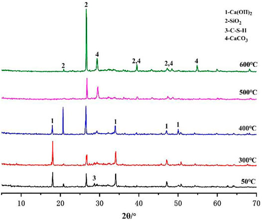
FIGURE 9. XRD diffraction patterns of C3 cement paste under different curing environments.
According to the above analysis, when the cement paste is cured at high temperatures (300–600°C) and under a CO2 environment, the CaCO3 phase forms in the C3 cement paste but not in C1, indicating that the C1 cement paste does not corrode. This means that the corrosion resistance of the C1 cement slurry system in high-temperature and acidic environment is much higher than that of the C3 cement slurry system.
3.6 Thermogravimetry
Thermal analysis can be used to identify amorphous phases that are difficult to detect by XRD. Figure 10 presents the mass loss rate curve of C1 the cement pastes cured at different temperatures and under CO2 environments. Figure 10 shows that the mass loss of the C1 cement paste cured at 50°C is approximately 22.5%. At the test temperatures of 200–300°C, the C1 cement paste shows a mass loss, and combined with the resultsof the previous phase analysis, it shows that the dehydration and decomposition of C3ASH4 and Al(OH)3 mainly occur in this temperature range. C3ASH4 can be transformed into C2AS after dehydration and decomposition, and C2AS can still provide high strength for the C1 cement paste, which is consistent with the compressive strength test results. The mass loss of the cement paste cured at high temperature (300–600°C) is relatively low. This is because after high-temperature curing, the internal phase of the C1 cement paste underwent phase transformation and had a relatively stable crystal structure. Meanwhile, the density of the cement pastes improved, which is reflected in the improvement in the compressive strength and tensile strength. The above analysis shows that the C1 cement paste still has good stability after curing in a high-temperature and under a CO2 environment, indicating that CAC is more suitable for use in high-temperature environments.
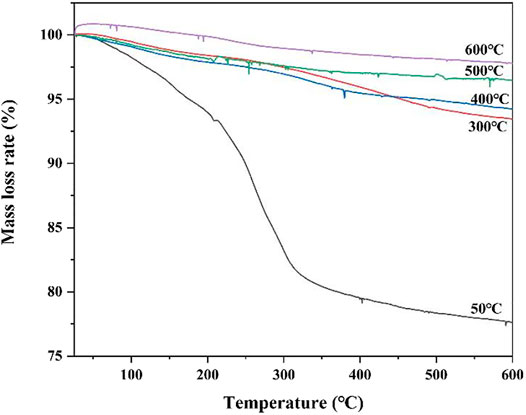
FIGURE 10. Mass loss curve of C1 cement paste cured at different temperatures.
3.7 Macroscopic and Microscopic Morphologies
Figure 11 presents the macro-morphology of the cement paste cured at different high temperatures. Figure 11shows that with the continuous increase in curing temperature, the degree of change in the morphology of the C1 cement paste decreases, a relatively dense morphology is maintained, and no cracks emerge. After curing at 300°C, the C2 cement paste begins to exhibit microcracks, and the microcracks increase and then decrease with an increase in temperature. The crack propagation trends in the C2 and C3 cements are similar. At the curing temperature of 600°C, a large number of chapped cracks appear on the surface of the C3 cement paste, and the integrity is completely destroyed.
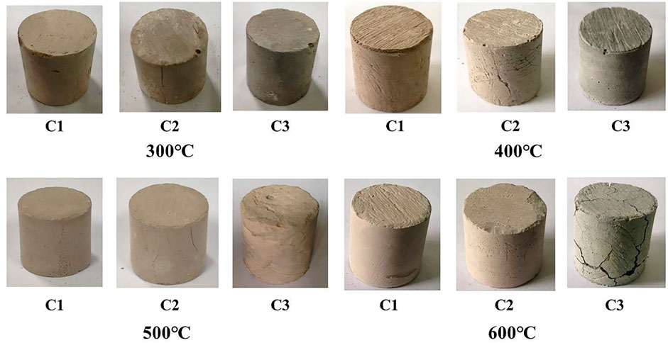
FIGURE 11. Macro morphology of cement paste cured at different high temperatures.
In this section, SEM was used to observe the surface of the C1 cement paste cured at 50, and 300–600°C in a CO2 environment, and the results are shown in Figure 13. Figure 12A shows the surface micromorphology of the cement paste cured at 50°C. The figure shows that the surface of the C1 cement paste cured at 50°C is relatively dense with only a few micropores. Figure 12B shows the C1 cement paste cured at 300 °C in a CO2 atmosphere. After high-temperature curing, the number of micropores of the C1 cement paste increases and the pore size tended to increase, but its structure is still relatively dense. With further increase in the curing temperature (400, 500, and 600°C, as shown in Figures 12C–E, respectively), the number of pores in the cement paste increase and the pore diameter was gradually expands, but the cement pastes maintain a relatively complete structure and show good mechanical properties. Meanwhile, large and concentrated pores were produced at the curing temperature of 600°C.
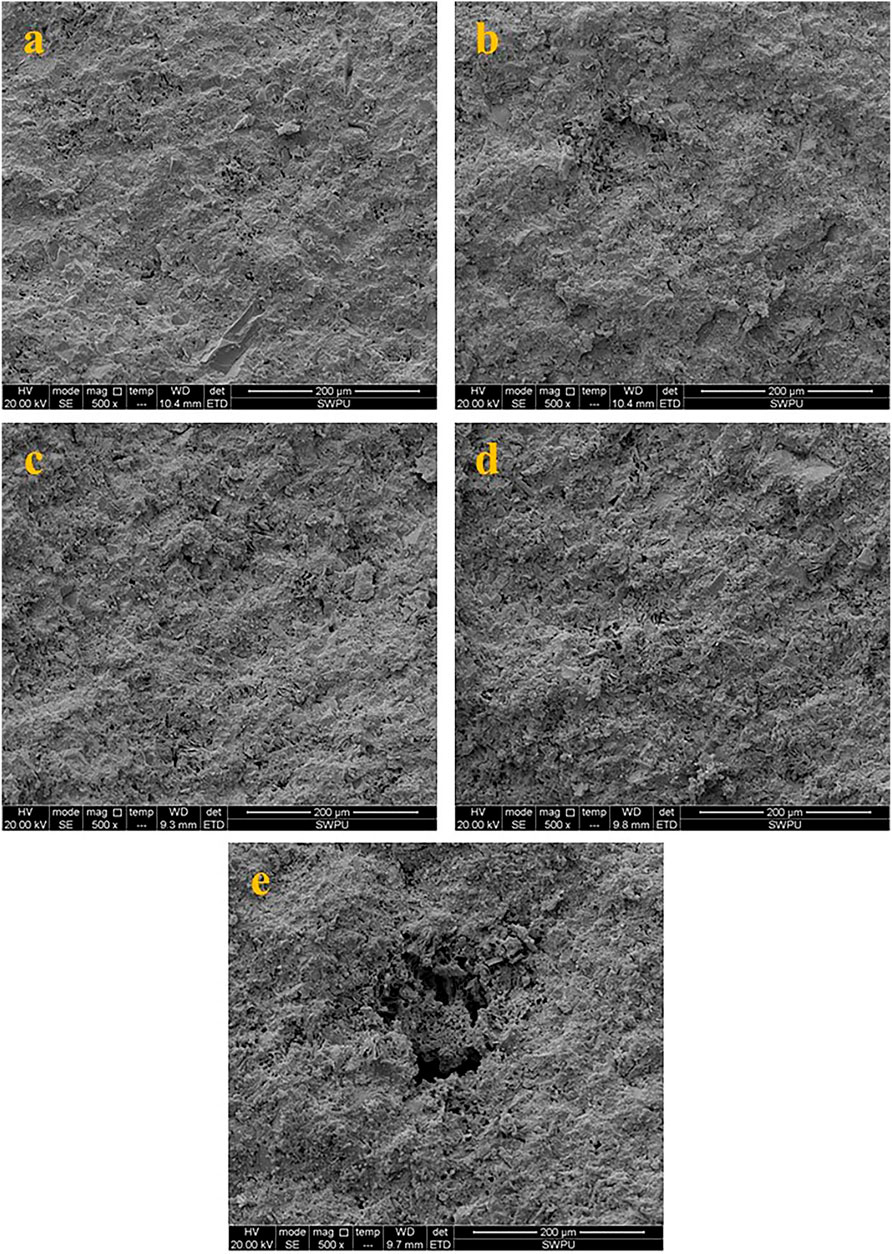
FIGURE 12. Surface micro morphology of the C1 cement paste cured at different temperatures (a: 50°C; b: 300°C; c: 400°C; d: 500°C; e: 600°C).
Figure 13 is a ×5,000 magnification of the microscopic morphology of the C1 cement paste cured under different temperatures in CO2. Figure 13A shows the microscopic morphology of the C1 cement paste cured at 50 °C. The C1 cement paste contains more intact hexagonal plate C2AH8 crystals, which grow in clumps and are one of the main sources of strength of CAC cement pastes at low temperatures (Hidalgo López et al., 2008). At the curing temperature of 300°C and a certain concentration of CO2, C2AH8 undergoes a crystal transformation into C3AH6 (C3AH6 is a spherical nodular prism that is, generally produced above 100°C); however, when the temperature rises to 300°C, the phase is dehydrated and shrinks, as shown in Figure 13B. At the curing temperature of 400°C, C2AH8 gradually undergoes dehydration and dissolution, the structure of the cement paste gradually loosens and a network interwoven solution forms. Meanwhile, more pores appear in the cement paste, as shown in Figure 13C. At the curing temperature of 500°C, the structure of the cement paste became loosens amount of hydration products gradually decreases, and interior of the cement paste exhibits honeycomb structure. This might adversely impact the strength of the cement paste, but the thermal stability of the C1 cement paste improved because of the presence of a high-temperature stabiliser. Therefore, the strength of the cement paste decreased only slightly. At the curing temperature of 600°C, there were more pores in the cement paste, and meanwhile, the cement paste had more microcracks owning to the effect of thermal stress. In addition, the C12A7 phase appears in the cement paste, which was produced by the crystallisation of C3AH6, and its crystal growth method was close to cross-type growth. The presence of C12A7 in the cement paste improved the strength of the cement paste and its wear resistance, which was consistent with the compressive strength change in the previous test.
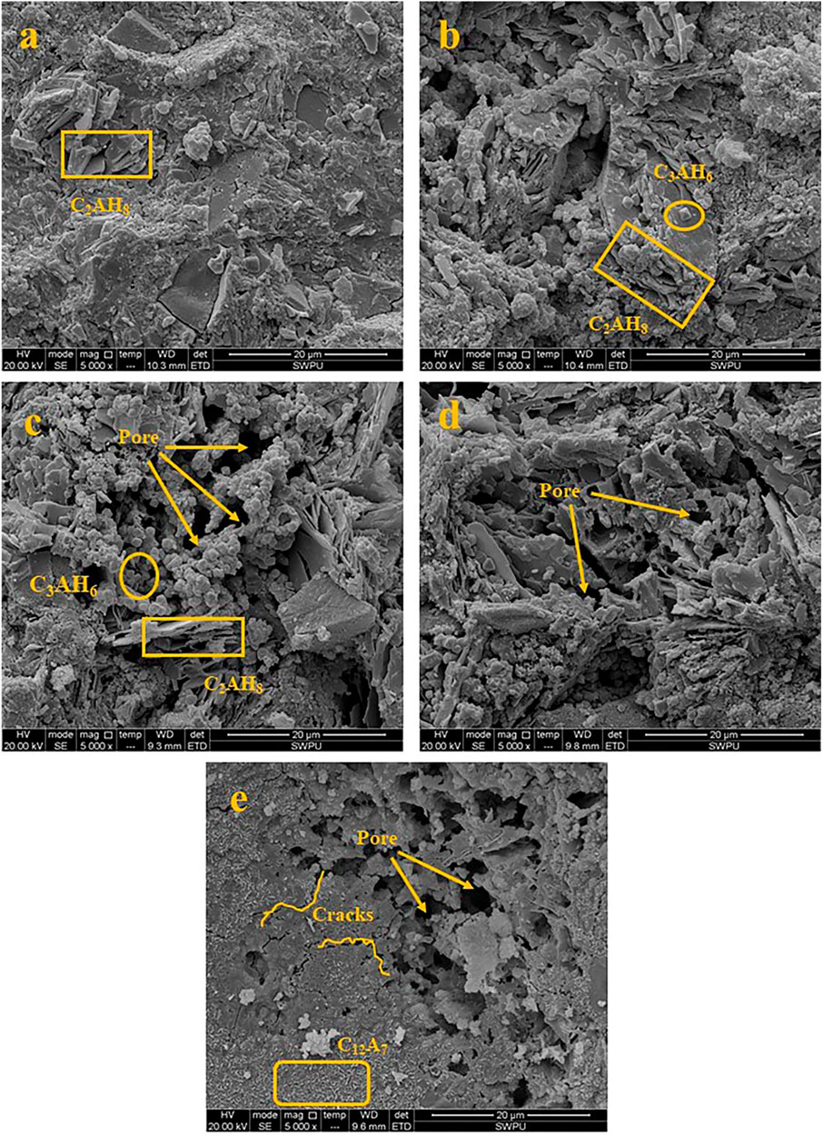
FIGURE 13. Micro morphology of the C1 cement paste cured at different temperatures (a: 50°C; b: 300°C; c: 400°C; d: 500°C; e: 600°C).
Based on the above analysis, the C1 cement slurry system still had a relatively complete and dense structure after curing at high temperatures in a CO2 environment, and there were many hydration products. In addition, no CaCO3 morphology material was found in the micromorphology of the cement paste. Combined with the XRD analysis results, it can be inferred that the C1 cement paste did not been corrode, indicating that it has good corrosion resistance.
4 Conclusion
In this study, the mechanical properties of the C1 cement slurry system (CAC with high-temperature stabiliser), C2 cement slurry system (CAC) and C3 cement slurry system (Portland cement with sand) under different curing conditions were studied. Meanwhile, the hydration mechanism and corrosion resistance mechanism of the C1 cement slurry system with good mechanical properties were explored, and the following conclusions were drawn.
The degree of degradation mechanical properties of the C1 cement slurry system under high temperatures in a CO2 corrosion environment is significantly lower than that of the C3 cement slurry system. The maximum strength of the C1 cement paste cured at 400°C reached 36.39 ± 0.37 MPa.
The addition of a high-temperature stabiliser improved the mechanical properties of CAC at low temperatures, reduced the formation of C3ASH4 in the cement paste at high temperatures, and improved the strength of the cement paste after high-temperature curing.
After the C1 cement slurry system was cured at high temperatures in a CO2 corrosive environment, the cement paste structure was still relatively dense. Main hydration products were C12A7, C2AS and other high-temperature resistant and dense structure phases, and no CaCO3 was found.
Compared with the C3 cement slurry system, the C1 cement slurry system had better high-temperature resistance and corrosion resistance, and it was more suitable for application under conditions of a burning reservoir in heavy oil thermal recovery.
Data Availability Statement
The original contributions presented in the study are included in the article/Supplementary Material, further inquiries can be directed to the corresponding author.
Author Contributions
JC: Conceptualization, Investigation, Writing-Original Draft, and Data Curation. GW: Validation, Resources, Writing—Review and Editing, and Supervision. ZW: Validation, Formal analysis, Investigation, and Data Curation. XX: Formal analysis and Project administration. XC: Methodology and Conceptualization.
Funding
This research was funded by CNOOC Limited Scientific Research Project “Ultra High Temperature and High Pressure Development Well Drilling and Completion Risk Assessment and Countermeasure Research” (No. YXKY-ZX-09-2021) and “Feasibility Study on Low Permeability Development of Bozhong 25-1S Oilfield 5 Well Block and Sha 3 Member” (No. 2021FS-02).
Conflict of Interest
The authors GW, ZW and XX are from CNOOC Research Institute Co. Ltd., Beijing. Authors JC and XC are from School of New Energy and Materials, Southwest Petroleum University, Chengdu; This research is under the overall responsibility of CNOOC Research Institute Co. Ltd., with the assistance of school of New Energy and Materials, Southwest Petroleum University. This research was funded by CNOOC Limited Scientific Research Project “Ultra High Temperature and High Pressure Development Well Drilling and Completion Risk Assessment and Countermeasure Research” (No. YXKY-ZX-09-2021) and “Feasibility Study on Low Permeability Development of Bozhong 25-1S Oilfield 5 Well Block and Sha 3 Member” (No. 2021FS-02). The fund's participation in this research is as follows: The fund provides support for research ideas, experimental equipment, materials, and funds for the research content of this article. The sponsor participated in the research design, data collection, analysis, interpretation, and the writing and submission of this article for publication.
The remaining authors declare that the research was conducted in the absence of any commercial or financial relationships that could be construed as a potential conflict of interest.
Publisher’s Note
All claims expressed in this article are solely those of the authors and do not necessarily represent those of their affiliated organizations, or those of the publisher, the editors and the reviewers. Any product that may be evaluated in this article, or claim that may be made by its manufacturer, is not guaranteed or endorsed by the publisher.
Acknowledgments
The authors appreciate the support of the CNOOC Limited Scientific Research Project “Ultra High Temperature and High Pressure Development Well Drilling and Completion Risk Assessment and Countermeasure Research” and “Feasibility Study on Low Permeability Development of Bozhong 25-1S Oilfield 5 Well Block and Sha 3 Member”. The authors would also like to thank the Advanced Cementing Materials Research Center of SWPU for their kind assistance with the experiments.
References
Abid, K., Gholami, R., Choate, P., and Nagaratnam, B. H. (2015). A Review on Cement Degradation under CO 2 -rich Environment of Sequestration Projects. J. Nat. Gas Sci. Eng. 27, 1149–1157. doi:10.1016/j.jngse.2015.09.061
Achang, M., and Radonjic, M. (2021). Adding Olivine Micro Particles to Portland Cement Based Wellbore Cement Slurry as a Sacrificial Material: A Quest for the Solution in Mitigating Corrosion of Wellbore Cement. Cement and Concrete Composites 121, 104078. doi:10.1016/j.cemconcomp.2021.104078
American Petroleum Institute (2013). API RP 10B-2, Recommended Practice for Testing Well Cements, 124.
Askarova, A., Turakhanov, A., Markovic, S., Popov, E., Maksakov, K., Usachev, G., et al. (2020). Thermal Enhanced Oil Recovery in Deep Heavy Oil Carbonates: Experimental and Numerical Study on a Hot Water Injection Performance. J. Pet. Sci. Eng. 194, 107456. doi:10.1016/j.petrol.2020.107456
Chavda, M. A., Bernal, S. A., Apperley, D. C., Kinoshita, H., and Provis, J. L. (2015). Identification of the Hydrate Gel Phases Present in Phosphate-Modified Calcium Aluminate Binders. Cement Concrete Res. 70, 21–28. doi:10.1016/j.cemconres.2015.01.007
Chen, T., Bai, M., and Gao, X. (2021). Carbonation Curing of Cement Mortars Incorporating Carbonated Fly Ash for Performance Improvement and CO2 Sequestration. J. CO2 Utilization 51, 101633. doi:10.1016/j.jcou.2021.101633
Chen, T., Xu, P., Gao, X., Wang, T., and Qin, L. (2022). New Sights in Early Carbonation of Calcium Silicates: Performance, Mechanism and Nanostructure. Construction Building Mater. 314, 125622. doi:10.1016/j.conbuildmat.2021.125622
Cheng, X., Dong, Q., Ma, Y., Zhang, C., Gao, X., Yu, Y., et al. (2019). Mechanical and thermal Properties of Aluminate Cement Paste with Blast Furnace Slag at High Temperatures. Construction Building Mater. 228, 116747. doi:10.1016/j.conbuildmat.2019.116747
China National Standard GB/T 1939-2012 Oil Well Cement Test Method (2012). China National Standard GB/T 1939-2012 Oil Well Cement Test Method.
Dener, M., Karatas, M., and Mohabbi, M. (2021). High Temperature Resistance of Self Compacting Alkali Activated Slag/portland Cement Composite Using Lightweight Aggregate. Construction Building Mater. 290, 123250. doi:10.1016/j.conbuildmat.2021.123250
El-Gamal, S. M. A., Abo-El-Enein, S. A., El-Hosiny, F. I., Amin, M. S., and Ramadan, M. (2018). Thermal Resistance, Microstructure and Mechanical Properties of Type I Portland Cement Pastes Containing Low-Cost Nanoparticles. J. Therm. Anal. Calorim. 131, 949–968. doi:10.1007/s10973-017-6629-1
Fernández-Jiménez, A., Vázquez, T., and Palomo, A. (2011). Effect of Sodium Silicate on Calcium Aluminate Cement Hydration in Highly Alkaline Media: A Microstructural Characterization. J. Am. Ceram. Soc. 94, 1297–1303. doi:10.1111/j.1551-2916.2010.04242.x
Frías, M., Martínez-ramírez, S., and De, R. V. (2022). Cement and Concrete Research New Scientific Evidence of the Effect of High Temperatures and Long Curing Times on MK-Blended Cement Paste Mineralogy, 152. doi:10.1016/j.cemconres.2021.106657
He, P., Zhang, B., Lu, J.-X., and Poon, C. S. (2020). A Ternary Optimization of Alkali-Activated Cement Mortars Incorporating Glass Powder, Slag and Calcium Aluminate Cement. Construction Building Mater. 240, 117983. doi:10.1016/j.conbuildmat.2019.117983
Hidalgo, A., García, J. L., Alonso, M. C., Fernández, L., and Andrade, C. (2009). Microstructure Development in Mixes of Calcium Aluminate Cement with Silica Fume or Fly Ash. J. Therm. Anal. Calorim. 96, 335–345. doi:10.1007/s10973-007-8439-3
Hidalgo López, A., García Calvo, J. L., García Olmo, J., Petit, S., and Alonso, M. C. (2008). Microstructural Evolution of Calcium Aluminate Cements Hydration with Silica Fume and Fly Ash Additions by Scanning Electron Microscopy, and Mid and Near-Infrared Spectroscopy. J. Am. Ceram. Soc. 91, 1258–1265. doi:10.1111/j.1551-2916.2008.02283.x
Jain, P., Stenby, E. H., and Von Solms, N. (2010). Compositional Simulation of In-Situ Combustion EOR: A Study of Process Characteristics, SPE - DOE Improv. Oil Recover. Symp. Proc. 2, 934–956. doi:10.2118/129869-ms
Jiang, D., Jiang, D., Lv, S., Cui, S., Sun, S., Song, X., et al. (2021). Effect of Flame-Retardant rice Straw Fibers on Properties of Fiber Cement-Based Composites at High Temperatures. J. Building Eng. 44, 102923. doi:10.1016/j.jobe.2021.102923
Jiang, D., Jiang, D., Lv, S., Cui, S., Sun, S., Song, X., et al. (2021). Effect of Modified Wheat Straw Fiber on Properties of Fiber Cement-Based Composites at High Temperatures. J. Mater. Res. Tech. 14, 2039–2060. doi:10.1016/j.jmrt.2021.07.105
Klaus, S. R., Neubauer, J., and Goetz-Neunhoeffer, F. (2013). Hydration Kinetics of CA2 and CA-Investigations Performed on a Synthetic Calcium Aluminate Cement. Cement Concrete Res. 43, 62–69. doi:10.1016/j.cemconres.2012.09.005
Lee, N. K., Koh, K. T., Park, S. H., and Ryu, G. S. (2017). Microstructural Investigation of Calcium Aluminate Cement-Based Ultra-high Performance concrete (UHPC) Exposed to High Temperatures. Cement Concrete Res. 102, 109–118. doi:10.1016/j.cemconres.2017.09.004
Mostafa, N. Y., Zaki, Z. I., and Abd Elkader, O. H. (2012). Chemical Activation of Calcium Aluminate Cement Composites Cured at Elevated Temperature. Cement and Concrete Composites 34, 1187–1193. doi:10.1016/j.cemconcomp.2012.08.002
Pahlavan, H., and Rafiqul, I. (1995). Laboratory Simulation of Geochemical Changes of Heavy Crude Oils during thermal Oil Recovery. J. Pet. Sci. Eng. 12, 219–231. doi:10.1016/0920-4105(94)00047-8
Pang, Z., Lyu, X., Zhang, F., Wu, T., Gao, Z., Geng, Z., et al. (2018). The Macroscopic and Microscopic Analysis on the Performance of Steam Foams during thermal Recovery in Heavy Oil Reservoirs. Fuel 233, 166–176. doi:10.1016/j.fuel.2018.06.048
Quercia, G., Spiesz, P., Hüsken, G., and Brouwers, H. J. H. (2014). SCC Modification by Use of Amorphous Nano-Silica. Cement and Concrete Composites 45, 69–81. doi:10.1016/j.cemconcomp.2013.09.001
Strelets, L. A., and Ilyin, S. O. (2021). Effect of Enhanced Oil Recovery on the Composition and Rheological Properties of Heavy Crude Oil. J. Pet. Sci. Eng. 203, 108641. doi:10.1016/j.petrol.2021.108641
Suchorzewski, J., Tejchman, J., and Nitka, M. (2018). Discrete Element Method Simulations of Fracture in concrete under Uniaxial Compression Based on its Real Internal Structure. Int. J. Damage Mech. 27, 578–607. doi:10.1177/1056789517690915
Tobón, J. I., Payá, J., and Restrepo, O. J. (2015). Study of Durability of Portland Cement Mortars Blended with Silica Nanoparticles. Construction Building Mater. 80, 92–97. doi:10.1016/j.conbuildmat.2014.12.074
Ukrainczyk, N., and Matusinović, T. (2010). Thermal Properties of Hydrating Calcium Aluminate Cement Pastes. Cement Concrete Res. 40, 128–136. doi:10.1016/j.cemconres.2009.09.005
Wu, K., Han, H., Rößler, C., Xu, L., and Ludwig, H. M. (2021). Rice Hush Ash as Supplementary Cementitious Material for Calcium Aluminate Cement – Effects on Strength and Hydration. Constr. Build. Mater. 302. doi:10.1016/j.conbuildmat.2021.124198
Yang, S., Lu, J.-X., and Poon, C. S. (2021). Recycling of Waste Glass in Cement Mortars: Mechanical Properties under High Temperature Loading. Resour. Conservation Recycling 174, 105831. doi:10.1016/j.resconrec.2021.105831
Yue, H., Pang, W., Duan, Y., Zhang, T., He, Z., Deng, D., et al. (2013). Integral Completion Technique for Heavy Oil Thermal Recovery. SPE 165518, 11–13. doi:10.2118/165518-ms
Zhang, C., Cai, J., Xu, H., Cheng, X., and Guo, X. (2020). Mechanical Properties and Mechanism of Wollastonite Fibers Reinforced Oil Well Cement. Construction Building Mater. 260, 120461. doi:10.1016/j.conbuildmat.2020.120461
Zhang, J., Wang, C., and Peng, Z. (2021). Corrosion Integrity of Oil Cement Modified by Environment Responsive Microspheres for CO2 Geologic Sequestration wells. Cem. Concr. Res. 143. doi:10.1016/j.cemconres.2021.106397
Zhang, X., Zhang, X., Li, Y., Hu, K., Mao, D., Luo, L., et al. (2021). Graphite-reinforced Portland Cement Composites at Alternate Ultra-high Temperatures. Powder Tech. 378, 647–658. doi:10.1016/j.powtec.2020.10.039
Keywords: aluminate cement, high temperature, mechanical properties, mechanism of action, CO2
Citation: Wu G, Wu Z, Xing X, Cai J and Cheng X (2022) Effect of CO2 on the Hydration of Aluminate Cement Under Conditions of Burning Reservoir in Heavy Oil Thermal Recovery. Front. Mater. 9:833851. doi: 10.3389/fmats.2022.833851
Received: 12 December 2021; Accepted: 03 February 2022;
Published: 22 February 2022.
Edited by:
Hanfeng Liang, Xiamen University, ChinaReviewed by:
Sifei Zhuo, Northwestern Polytechnical University, ChinaJiakai Liu, King Abdullah University of Science and Technology, Saudi Arabia
Qiu Jiang, University of Electronic Science and Technology of China, China
Copyright © 2022 Wu, Wu, Xing, Cai and Cheng. This is an open-access article distributed under the terms of the Creative Commons Attribution License (CC BY). The use, distribution or reproduction in other forums is permitted, provided the original author(s) and the copyright owner(s) are credited and that the original publication in this journal is cited, in accordance with accepted academic practice. No use, distribution or reproduction is permitted which does not comply with these terms.
*Correspondence: Xiaowei Cheng, Y2hlbmd4d0Bzd3B1LmVkdS5jbg==