 Guo-an Liu
 Xin Wang1,2*
94% of researchers rate our articles as excellent or good
Learn more about the work of our research integrity team to safeguard the quality of each article we publish.
Find out more
ORIGINAL RESEARCH article
Front. Mater. , 14 February 2022
Sec. Structural Materials
Volume 9 - 2022 | https://doi.org/10.3389/fmats.2022.832579
This article is part of the Research Topic Strain Hardening Cementitious Composites: material development, performance characterization, structural, and 3D printing applications View all 13 articles
Unreinforced masonry structures are vulnerable to seismic action, especially with window openings. Therefore, a strengthening technique needs to be proposed to improve the seismic performance of the confined masonry walls with window openings. In this study, hybrid fibers modified reactive powder concrete (HFMRPC) with good composite action to masonry walls were obtained through material tests. Then, the HFMRPC material was used as a coating to strengthen or repair the confined masonry walls with window openings by single-sided full coverage, double-sided full coverage, single-sided coverage in piers, and double-sided coverage in piers. To investigate the effect of HFMRPC coating on strengthening or repairing the confined masonry walls with window openings. Seven half-scale masonry walls were tested under in-plane quasi-static horizontal loading. The results indicated that the retrofitting technology using HFMRPC coating could effectively enhance the load-bearing capacity, energy dissipation capacity of the strengthened and repaired masonry walls and delay their stiffness degradation. Among the above-mentioned strengthening methods, the strengthening in piers significantly enhanced the ductility and energy dissipation of the specimens, and the double-sided full coverage enhanced the load-bearing capacity and stiffness of the specimens. Finally, a simplified analysis method was proposed to calculate the shear bearing capacity of the strengthened or repaired confined masonry walls with window openings based on theoretical analysis and test results.
As one of the primary structural forms with a long history, masonry structure is widely used in mainland China. In recent years, two major earthquakes, i.e., Wenchuan Earthquake in 2008 and Yushu Earthquake in 2010, happened in mainland China. Due to the various anisotropy and brittleness of brick, existing masonry structures have a greater vulnerability in earthquakes and are severely damaged under strong earthquake effects (Tai et al., 2011). Meanwhile, any masonry opening can seriously weaken the shear bearing capacity, ductility, and initial stiffness, which changes the failure pattern of masonry walls (Shariq et al., 2008). Therefore, masonry walls with window openings were severely damaged under earthquakes. An effective strengthening technique is needed to improve the seismic performance of masonry structures, especially for those with window openings.
Different kinds of Fiber-reinforced polymers (FRP) materials are widely used to reinforce masonry walls are proved to be an effective reinforcement method (Foraboschi, 2016; Guerreiro et al., 2018; Kalali and Kabir, 2012). Masonry walls reinforced with FRP can effectively improve the in-plane shear strength (Konthesingha et al., 2013; Leal-Graciano et al., 2020). The integrity of the masonry wall can be maintained under large deformation caused by the lateral displacement, and the collapse of the wall is also delayed, which enhances the deformation capacity and energy dissipation of the masonry wall (El-Diasity et al., 2015). However, organic binders (epoxy resin, etc.) are applied to FRP during strengthening construction. Hence, there are problems of poor behavior in bond at high temperature and its irreversibility and limitations such as incompatibility and poor coordination between FRP and masonry substrates (Bui et al., 2015). It will not only cause damage to human health but also be detrimental to the environment. Some progress attempts have been made to use inorganic matrices instead of FRP bonding as the strengthening method to solve these problems. A composite system consisting of continuous multiaxial hybrid fibers embedded in the mortar-based matrix was proposed and denominated Textile Reinforced Mortar (TRM). Internationally, the inorganic composite systems reinforced by textile are also named Textile Reinforced Concrete/Cement (TRC) (Bisby et al., 2011; Cheng et al., 2020), Fiber Reinforced Cementitious Matrix/Mortar (FRCM) (Del Zoppo et al., 2019a; Mercedes et al., 2020), Cementitious Matrix Grid (CMG) (Prota et al., 2006), Composite Reinforced Mortar (CRM) (Del Zoppo et al., 2019b), or Inorganic Matrix-Grid (IMG) (Augenti et al., 2011; Parisi et al., 2013). The research has shown that the application of TRM is served as an alternative to the application of FRP. Since TRM was proven effective in strengthening concrete specimens, it was also introduced into strengthening masonry structures (Papanicolaou et al., 2007; Papanicolaou et al., 2008). The brittle failure of masonry walls can be improved by using the TRM strengthening method, which ensures the integrity at the failure and increases the ultimate load of the strengthened masonry wall (Dong et al., 2020; Garcia-Ramonda et al., 2020). With the growing awareness of environmental protection, more researchers have started to use green and sustainable plant fibers such as flax, hemp, coir, sisal, and jute as reinforcement materials in inorganic composites, which can be served as alternatives to traditional inorganic fibers and are more friendly to the environment (Ferrara et al., 2020). However, the construction procedure of the TRM system is complicated, which requires a smooth application of mortar before laying the single or multiple layers of fibers on the wall surface. The lateral strength of the masonry structures strengthened with the TRM system is lower than that of those strengthened with FRP. Meanwhile, there is still some uncertainty about the long-term durability of TRM composite systems in freeze-thaw cycles, hygrothermal environments, and alkaline environments (Al-Lami et al., 2020).
Engineered cementitious composite (ECC) is a material with strain hardening properties and multiple crack development under the tensile and shear loading. The tensile and shear properties of the specimens are improved due to the “bridge effect” of the fibers within the ECC (Cai et al., 2021; Ding et al., 2022; Li and Leung, 1992). Many researchers have used ECC to strengthen masonry walls, and test results indicated that the stiffness, ductility, and energy dissipation capacity of the masonry structures strengthened with ECC can be effectively improved (Deng and Yang, 2020; Dong et al., 2022a; Dong et al., 2022b; Niasar et al., 2020). Although the shear strength of the masonry structure continues to be increased as the thickness of ECC coating, the increased rate of the shear strength gradually decreases (Lin et al., 2014). In addition, with the increasing thickness of the masonry wall, the retrofitting effect of ECC coating becomes less and less obvious (van Zijl and De Beer, 2019). Compared with the other strengthening methods, constructing the additional plaster coating is relatively simple, which effectively shortens the construction period and reduces the damage to the external facade and the initial wall. Furthermore, the application of the plaster coating can also guarantee minimal interference to the use of the current building during construction. Therefore, an effective plastered strengthening material for masonry structures that need to be developed is significant. Reactive powder concrete (RPC) coating has been used to strengthen and repair the confined masonry walls (Wang et al., 2019). The in-plane seismic behavior of the masonry walls strengthened with RPC coating was improved significantly. Due to the interaction between RPC coating and the masonry wall, the bond between the mortar and brick interface was enhanced, and the restriction between the concrete frame and masonry wall was also improved (Wang et al., 2021).
In this paper, a retrofitting technology using hybrid fibers modified reactive powder concrete (HFMRPC) was used to strengthen or repair the confined masonry walls with window openings. A mixed proportion of HFMRPC material with moderate compressive strength but an excellent surface bond property with brick was developed. Then, seven half-scale confined masonry walls with window openings were constructed, and six of them were strengthened or repaired with HFMRPC coating. Subsequently, the unstrengthened, strengthened, and repaired masonry walls were tested under the in-plane quasi-static lateral loading. The effectiveness of the HFMRPC strengthening technology was evaluated in terms of seismic performance parameters such as the load-carrying capacity, failure mode, crack development, displacement ductility, stiffness, and energy dissipation of the masonry walls. In addition, a simplified calculation method for the shear resistance of the confined masonry walls with window openings was proposed based on the theoretical analysis and test results.
Traditional RPC is characterized by high strength, toughness, and fluidity. Compared with the traditional RPC, the compressive strength of brick is much less. If the difference of compressive strength between the bricks and the strengthening materials is too great, it is neither economic nor conducive to the coordination of the two materials. Furthermore, due to the high fluidity of RPC, it is difficult to be used as plastering without using molds when strengthening masonry structures. Based on the above problems, the traditional RPC needs to be modified according to the design theory of RPC. The modified RPC (i.e., HFMRPC) can be adapted to the characteristics of the masonry wall, and it has a good bond with the masonry wall to ensure the better integrity of the strengthened structure under seismic action. Therefore, the strength and fluidity of the modified RPC need to be reduced while its ductility and adhesion need to be increased.
In this study, the hybrid-fiber modified reactive powder concrete (HFMRPC) matrix consists of ordinary Portland cement, medium river sand, fly ash, mineral powder, and silica fume. Then, steel fibers (diameter: 0.2 mm, length: 13 mm), polypropylene (PP) fibers (diameter: 45 μm, length: 18–20 mm), and high-efficiency polycarboxylate water reducer agent (water-reducing rate ≥35%) were also added to the matrix. The fluidity, adhesion, and compressive strength were used as the screening conditions for the mixture to ensure the composite action of HFMRPC coating and brick wall. Different mix proportions were designed to explore the effect of the water-cement ratio and water reducer agent on the HFMRPC material. The mixed proportions of HFMRPC in this study are listed in Table 1.
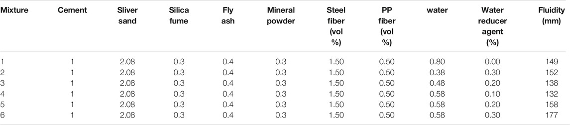
TABLE 1. Mix proportions of HFMRPC.
First, the raw materials, including cement, medium river sand, mineral powder, silica fume, and fly ash, were put into the mixer and mixed in turn. Then, it was followed by the even addition of steel fibers and PP fibers to the mixture. During the mixed process, the fiber agglomeration should be prevented. The dry materials should be pre-mixed for more than 4 min to ensure that all materials were well mixed. Finally, the water and water reducer agent were added, and then the mixture was stirred again for more than 4 min. After the HFMRPC was well stirred, three cubes (100 mm × 100 mm × 100 mm) were prepared for each batch. After 24 h of natural curing, the tested cubes were demolded. Then, after 28 days of natural curing, the average compressive strength of the three cubes for each batch was measured.
The compressive strengths of the HFMRPC materials with various mix proportions are shown in Figure 1, and the fluidity of each mixture is listed in Table 1. The required strength of the reinforcing material is not high as the strength of brick is relatively low. However, fluidity and viscosity are the key factors to achieve plastering. The viscosity was gradually increased as the fluidity was decreased. By comparing the mixtures 4, 5, and 6, it can be found that at the same water-binder ratio, the flowability and compressive strength of the mixtures increased with the increase of the water reducer agent, while their viscosity was reduced. When comparing the mixtures 2, 3, and 4, the compressive strength decreased significantly with the increase of the water-binder ratio. In addition, the addition of fiber to the matrix resulted in a decrease in flowability but an improvement in viscosity. Therefore, the compressive strength of HFMRPC was reduced by increasing the water-binder ratio, and the difference in compressive strength between the brick and HFMRPC was also decreased. Also, with the reduction of the water reducer agent, the flowability and compressive strength of HFMRPC was reduced, but its viscosity was increased, which can be applied on the surface of masonry walls by using hand-trowel. Finally, mixture four was selected for strengthening and repairing the masonry structures based on the test results.
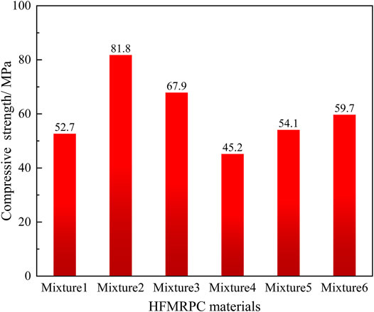
FIGURE 1. Compressive strength of the HFMRPC materials with various mix proportions.
Seven half-scale masonry walls consisting of a ring beam, two confining columns, a reinforced concrete footing, and a masonry wall with a window were constructed. Two-bolt holes were reserved in the reinforced concrete footings of the brick walls, and then they were firmly anchored to the strong laboratory floor with 100 mm-diameter high strength bolts. The bolts can avoid any uplift and slip when the horizontal displacement loading was applied. All the brick walls were constructed by an experienced bricklayer with a typical bond pattern and the same construction, which included the low-strength mortars, clay bricks, and uneven mortar joints. These construction technologies were intentionally used to construct the confined masonry walls because these walls were widely applied in the countryside of mainland China.
The details of the tested walls are shown in Figure 2. The aspect ratio of the seven walls was 1:1. Specimen URMW-1 was the controlled specimen without any strengthened measure. Specimen SRMW-2 was strengthened with overall HFMRPC coating only on one side to prevent the indoor space from being occupied. Specimen DRMW-3 was strengthened with the overall HFMRPC coating on both sides. Specimen DRMW-4 was strengthened in the same way as the specimen DRMW-3, and only the thickness of the HFMRPC coating was different. Specimen SPRW-5 was single-side strengthened with HFMRPC coating only in the piers. Specimen DPRW-6 was double-side strengthened with HFMRPC coating only in the piers to improve the local rigidity of the masonry wall. Specimen DRUW-7 was repaired and strengthened with HFMRPC coating after the URMW-1 was tested. The differences in strengthening methods are shown in Table 2. Before the test, white latex paint was applied on the surface of the specimens for a better observation of the cracks during cyclic loading.
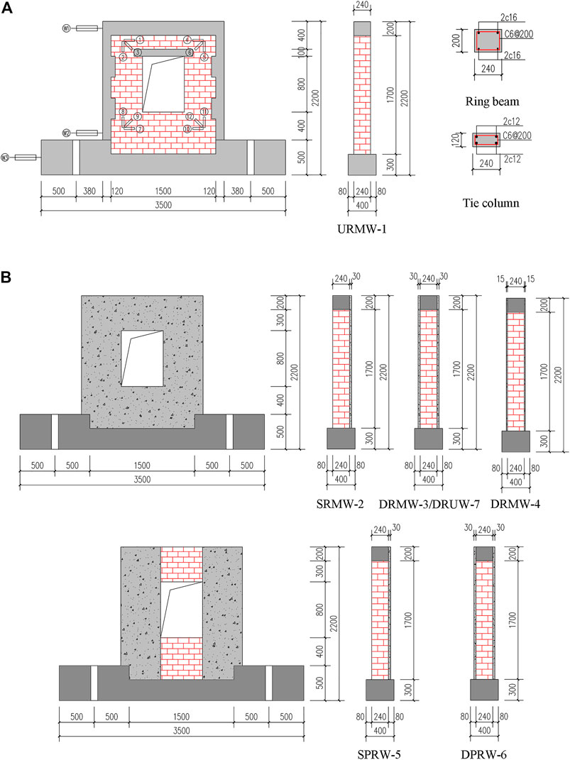
FIGURE 2. Details of the tested wall (unit: mm) (A) the layout, reinforcement, and facades of tested walls (B) strengthening methods for the tested walls.
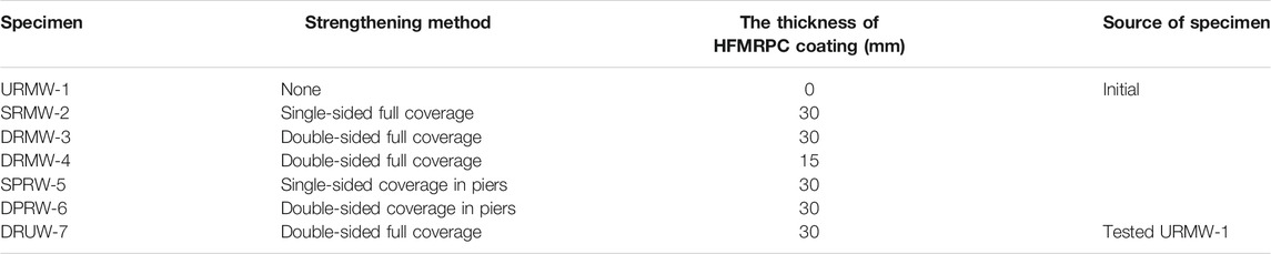
TABLE 2. Strengthening methods for the tested walls.
The first procedure for strengthening the masonry wall was to deal with its surface. After the strength of the mortar reached to the standard of use, all the loose cement mortar and dust were removed from the surface of the masonry wall that was required to be strengthened. After that, the polished specimens were got wet by sprinkling water and then placed in a ventilated place until the dry surface with a saturated condition was reached. Finally, HFMRPC coating with various thicknesses was smeared on the uneven masonry surface. When repairing the specimen URMW-1 after being tested, the crushed bricks were first removed, and then the dislodged and broken mortar joints were also cleared, and then the same procedure was taken as that for strengthening the other specimens. Furthermore, it was worth noting that the hole joints generated from removing the broken bricks and mortar in the masonry walls should be first filled with HFMPRC plastering. Finally, the specimens were strengthened with the HFMRPC coating. The 28-days outdoor curing was recommended before the strengthened specimens were used. Furthermore, the strengthened specimens should be kept moist during the first week of the curing process to prevent the cracking caused by the shrinkage of the coating.
The mechanical properties of the bricks, cement mortar, reinforcing bars, HFMRPC, and concrete used in this study were determined according to the standardized testing procedures. The confined masonry walls were built using sintered clay bricks with the standard dimension of 240 mm × 115 mm × 53 mm (length × height × thickness). Furthermore, all the HFMRPC cubes, mortar cubes, and concrete cubes were made from the same batch of materials and cured under the same conditions when the masonry walls were constructed. The measured compressive strengths of the bricks, cement mortar, HFMRPC, and concrete used in this study are listed in Table 3.

TABLE 3. Compressive strength of the materials.
In this study, the seven half-scale specimens were tested in the Engineering Structure Disaster Prevention and Mitigation Laboratory of Shandong Architectural University, China. The actual force boundary conditions of the wall were simulated by the loading system, which included the constant vertical loading and the lateral cyclic loading with a displacement-controlled loading protocol. A 50 kN hydraulic jack (MTS) installed on the ring beam was used to impose the horizontal cyclic loading with displacement control. After the specimen was installed, a distribution steel beam was placed on the top of the specimen. A vertical load of 200 kN was applied on the top center of the distribution steel beam using a 100 t on a hydraulic jack to simulate a constant vertical compressive stress of 0.5 MPa transmitted from the gravity load. During the test, the vertical load was kept constant. The setup used for the quasi-static cyclic test is shown in Figure 3.
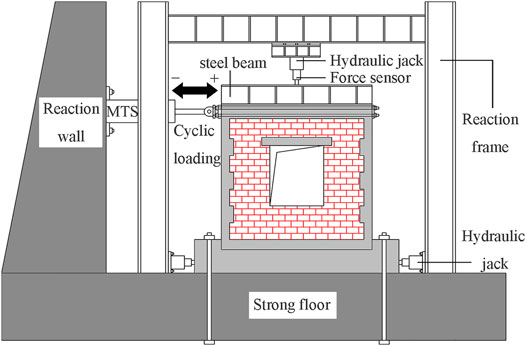
FIGURE 3. Schematic diagram of the test setup.
The horizontal loading pattern is shown in Figure 4. The displacement loading was divided into four stages, in which each level of displacement loading was cycled twice. The positive and negative displacements were the push and pull directions, respectively, as shown in Figure 3. The first stage was the elastic stage, and the displacement increment was chosen to start from 0.2 mm until the specimen was cracked to observe the development of the cracking process. The second stage was the elastic-plastic stage after cracking until the specimen yielded, and the displacement increment was increased to 0.4 mm. Subsequently, the third stage was the plastic stage after yielding until the peak load, and the displacement increment was changed to a higher level of 0.8 mm. Finally, the displacement increment in the fourth stage was turned into 1.6 mm after the peak load, and the bearing capacity continued to be decreased. According to the Chinese code (JGJ/T 101—2015), the test was loaded until the horizontal bearing capacity of the specimen dropped to 85% of the peak load.

FIGURE 4. Horizontal loading pattern.
The applied loads and displacements at the critical locations of the specimens were measured with two load cells and four linear variable displacement transducers (LVDTs), among which the lateral load was calibrated by a load cell installed in the MTS actuator. Another load cell was connected to the vertical hydraulic jack to guarantee the constant vertical load. The LVDT W1 was used to calibrate the horizontal displacement applied by the MTS actuator, which represented the horizontal displacement of the ring beam. The LVDT W2 was used to measure the horizontal displacement at the bottom of the specimen. The LVDT W3 was used to measure any possible slippage of the reinforced concrete footings relative to the strong laboratory floor. The LVDT W4 was placed at the middle of the ring beam to measure the displacement out-of-plane. The top of the specimen can move freely in-plane and out-of-plane, monitored in real-time by LVDT W4. During the test, the value of W4 was found to be small. Hence, the effect of out-of-plane bending on the specimen was negligible. The schematic layout of the displacement measurement points can be seen in Figure 2A. All LDVTs were connected to a computer-controlled data acquisition system. The visible crack patterns were continuously monitored after each load level was applied and marked on the specimens.
The failure mode and crack pattern for the unreinforced specimen URMW-1 are shown in Figure 5. The first crack in URMW-1 appeared at the upper corner of the window due to the stress concentration and then developed along the mortar joints. With increasing displacement, the cracks appeared at the bottom of the constructional columns, and the cracks at the window corners were gradually extended towards the diagonal direction in a stepped pattern. When the peak load was reached, the mortars continued to be spalled from bricks, and bricks in piers were crushed. Finally, the URMW-1 failed with the crushing of the piers and the column toe after the major shear cracks penetrated the edge of the constructional column. Meanwhile, the window was deformed, and an apparent inward convex from the window frame was observed. The failure mode for URMW-1 was a typical diagonal compression failure, which showed the characteristic of brittle damage. It indicated that the physical characteristics of bricks and the bonding capacity between bricks and mortar had an essential effect on the seismic bearing capacity for the URMW-1.
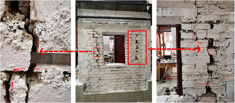
FIGURE 5. Failure mode and crack pattern for URMW-1 at ultimate displacement.
Figure 6 shows the failure mode and crack pattern for the single-side strengthened specimen SRMW-2. The first crack in SRMW-2 appeared in the mortar at the window corner on the unreinforced side. With increasing displacement, the window corners on both sides cracked successively and formed a stepped crack extending to the diagonal. When reached the failure displacement, the coating was partially separated from the edge of the constructional column. Moreover, the concrete at the bottom of the constructional column was crushed. The failure mode for SRMW-2 was a typical shear slip failure, and the brittle characteristic was significantly improved compared with URMW-1. The failure mode on both sides of the SRMW-2 was similar, where the shear failure developed from the diagonal cracks in the HFMRPC coating and the mortar joints near the window corner. On one side of the SRMW-2 that was not reinforced, the mortar joints were less damaged than URMW-1, mainly because the HFMRPC coating enhanced the bond between the brick and mortar and provided restraint and protection to the brick wall. It demonstrated that the bonding property between the coating and the brick wall was well under the horizontal cyclic loading, and both of them deformed collaboratively to bear the shear force together.
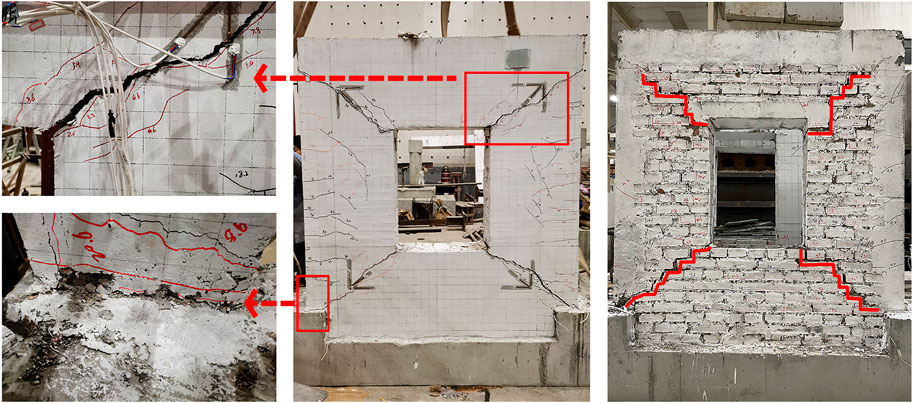
FIGURE 6. Failure mode and crack pattern for SRMW-2 at ultimate displacement.
As shown in Figure 7, the failure mode and crack pattern for specimens DRMW-3 and DRMW-4 were similar to specimen SRMW-2, both of which were typical shear slip failures with no significant improvement in the characteristics of brittle damage compared with the URMW-1. Both specimens were damaged with diagonal cracks on the coating, where the steel fibers were pulled out, and the PP fibers were broken. Meanwhile, at the edge of the sides of the constructional columns, there were only fine cracks, but no spalling occurred between the coatings and the brick walls. Furthermore, it was found that the bricks near the cracks were severely damaged after the coating was removed. The brick chips were bonded in the removal coating, indicating a good bond between the brick walls and coatings. The maximum width of the crack in DRMW-4 was wider than that in DRMW-3 at the time of failure. It indicated that the extent of the damage for the specimen was decreased with the increase of coating thickness. In brief, the integrity and stiffness were evenly increased due to the restriction of the double-sided coating. Hence, it resulted in a more even distribution of shear stress and made a pivotal contribution to improving the bearing capacity.
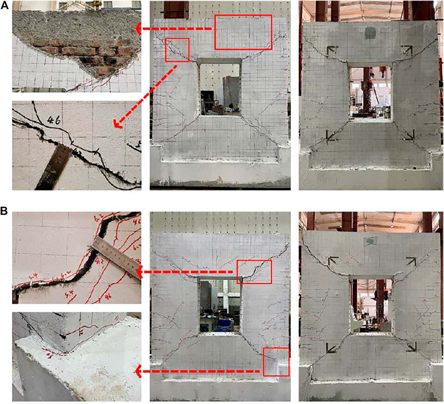
FIGURE 7. Failure mode and crack pattern for DRMW-3 and DRMW-4 at ultimate displacement (A) DRMW-3 (B) DRMW-4.
The failure mode and crack patterns for specimens SPRW-5 and DPRW-6 are shown in Figure 8. The first crack in both specimens appeared at the junction of the spandrels and the coating. As the loading continued, the shearing cracks of the spandrel developed diagonally along the mortar joints, and the concrete lintel beam on the upper part of the window also cracked. When the specimens reached the ultimate displacement, the spandrels were severely damaged and formed a characteristic “X-type” crack pattern on the side reinforced with the coating. Meanwhile, the edge of the coatings on the spandrels was separated from the wall. However, the piers on both sides were relatively intact due to the protection of the coating.
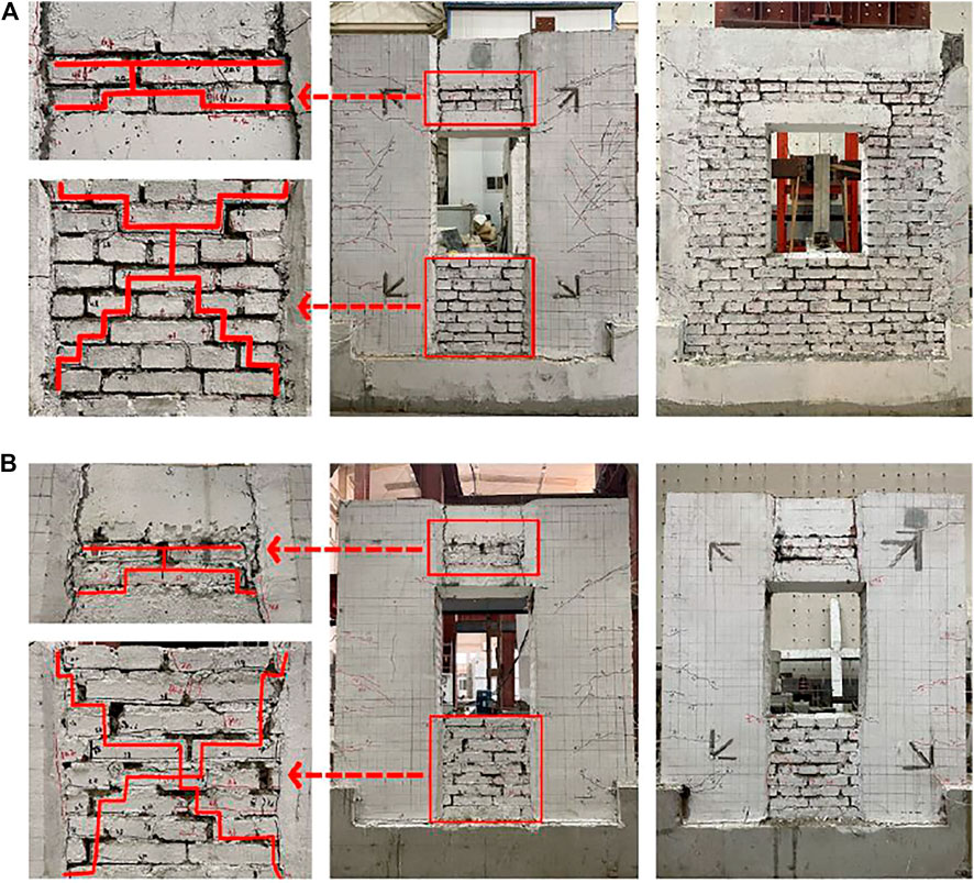
FIGURE 8. Failure mode and crack pattern for SPRW-5 and DPRW-6 at ultimate displacement (A) SPRW-5 (B) DPRW-6.
A mixed failure mode was observed in the specimens SPRW-5 and DRMW-6. It included a shear failure in the spandrels and a flexural failure in the piers. The two specimens exhibited the characteristic of ductile damage, showing a different failure mode from the other specimens. The two strengthening methods significantly increased the stiffness difference between the piers and spandrels. Therefore, it can be regarded that the strengthened piers were similar to two rigid columns, which were connected by a ring beam that was similar to a coupling beam in the shear wall. The damage to the specimens was caused by the generation of plastic hinges on the edge of the ring beam. Eventually, a rocking mechanism was generated on the rupture plane. This failure mode can consume a part of the earthquake energy in advance, which the seismic capacity of the spandrels was maximized, and the ductility of the specimens was also improved effectively.
In Figure 9, a shear slip failure was observed in the repaired specimen DRUW-7, the same as the specimen DRMW-3. The initial cracks developed from the four corners of the window and progressed along with the coating towards the diagonal direction in a stepped pattern. Eventually, the cracks at the bottom corner of the coating joined the shear crack at the bottom of the constructional columns, and the DRUW-7 failed. The brick, mortar joints, and concrete of the specimen URMW-1 had been damaged after the test. The constructional column at the bottom was also penetrated completely by shear cracks. Therefore, the damage extent of the DRUW-7 was more severe than that of the DRMW-3. The window of the URMW-1 developed significant plastic deformation at the time of failure, but after being repaired with HFMPRC coating, the shear stress was better redistributed due to the restraining effect of the coating, which prevented the continuous deformation of the window.
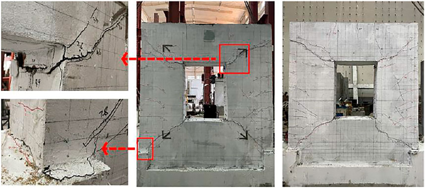
FIGURE 9. Failure mode and crack pattern for DRUW-7 at ultimate displacement.
The hysteretic curves of all specimens are shown in Figure 10. No significant strength and stiffness degradation were observed in the second cycle of each displacement loading. Hence, the hysteretic curves of the first cycle in each displacement loading step were selected for comparative analysis. Before each specimen cracked, the hysteresis curves were almost linear, while the shape of the hysteresis curves curved significantly after cracking. The specimens reached the peak load after a smooth rising period. Due to the continuous development of shear cracks during the loading process, the hysteretic curves of the specimens showed an inverse “S” shape at the failure.
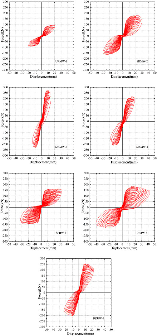
FIGURE 10. Hysteresis curves.
Due to the fragility of the bricks and the existence of window openings in the wall, the elastic deformation capacity of the controlled specimen URMW-1 was the lowest. Hence, a noticeable pinching effect in its hysteretic curve was observed. The URMW-1 experienced the most severe damage when the peak load was reached and produced a relatively large residual deformation and a significant slip. Nevertheless, the pinching behavior of the hysteretic curves was mitigated for all the strengthened specimens compared with the URMW-1. Although specimen SRMW-2 was only strengthened on one side by HFMRPC coating, the whole specimen remained intact after the failure. As the double-sided full coverage reinforcement increased the stiffness and integrity significantly, the pinching behavior of the hysteresis curve in specimen DRMW-3 was improved most obviously. Compared with the other specimens, the bearing capacity of specimen DRMW-3 was the highest, but it decreased fastest after reaching the peak load. The stiffness difference between the spandrels and piers in specimens SPRW-5 and DPRW-6 was increased through the strengthening in piers. Therefore, the earthquake-resistant behavior of the wall was fully exerted. This reinforcement decreased the bearing capacity at a flat rate, and the ductility was significantly improved. The hysteresis response of the repaired specimen DRUW-7 did not perform as well as the strengthened specimen DRMW-3, but it was significantly improved compared with the unstrengthened specimen URMW-1.
In summary, the hysteresis response of the strengthened or repaired specimens was effectively enhanced by using the proposed HFMRPC strengthening technique.
The skeleton curves of each specimen are compared in Figure 11. All specimens were in the linear elastic stage at the beginning of loading. Due to the different ways to strengthen the specimens using HFMRPC coating, the duration of the linear elastic stage was also related to the stiffness of the specimens. Hence, the improvement in the stiffness and the duration of the linear elastic stage were also different. Moreover, the horizontal load of the strengthened specimens was much higher than that of the unstrengthened specimen URMW-1 at the same horizontal displacement.
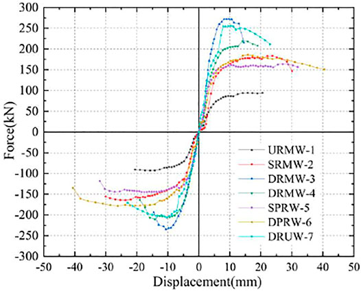
FIGURE 11. Skeleton curves of load-displacement.
Afterward, the specimens entered the elastic-plastic stage, where the slope of the skeleton curves and the stiffness gradually decreased, while the bearing capacity continued to be increased until the specimens reached the peak load. After reaching the peak load, the bearing capacity of all specimens started to decrease, among which, the bearing capacity of specimen URMW-1 continued to be decreased and was severely damaged. The specimens SRMW-2, DRMW-3, and DRMW-4 had severe cracking in the coating along the diagonal direction from the window corner, and the constructional columns were penetrated by the through-length shear cracks, which led to a sudden decline in the bearing capacity of the specimens. Compared with other specimens, the bearing capacity of specimens SPRW-5 and DPRW-6 was not much different from the single-sided reinforcement specimen SRMW-2, but their strength decreased slowly. It was mainly due to the large stiffness difference between the piers and spandrels after the piers were reinforced with the HFMPRC coating. The reinforcement method in piers enabled a full function of the spandrels and improved the deformation capacity of the specimens, which led to a slight decrease of the bearing capacity until the ductile failure occurred.
As shown in Table 4, the cracking load (Pcr) and peak load (Pu) of specimens were compared. When the specimens were reinforced with HFMRPC coating, the cracking and peak loads increased to different extents. Compared with the specimen URMW-1, the cracking load of specimen SRMW-2 was improved by 49.6%, while the improved extent for the cracking load of the other strengthened specimens ranged from 174.3 to 620.0%. In terms of peak load, the ultimate bearing capacity of the strengthened specimens SRMW-2, SRRW-5, and DPRW-6 increased by 85.5, 63.5, and 94.7%, respectively, while the improvement in the ultimate bearing capacity of the specimens DRMW-3 and DRMW-4 were much more significant (by 172.1 and 130.4%, respectively). The thickness of the coating in specimen SRMW-2 was the same as the total thickness of the coating in specimen DRMW-4. In contrast, the bearing capacity of specimen DRMW-4 was significantly higher than that of specimen SRMW-2, which indicated that the effect of double-sided coating reinforcement was particularly remarkable to enhance the bearing capacity. After the specimen DRUW-7 was repaired with the HFMRPC coating, its cracking load was almost the same as the reinforced specimen DRMW-3. However, due to the existing damage in the bricks, mortar joints, and concrete, the peak load of the specimen DRUW-7 was lower than specimen DRMW-3, and the peak load was only improved by 147.5% compared with the specimen URMW-1. It indicated that the HFMRPC coating had a strong composite restraint effect on the specimens and protected brick walls, which significantly enhanced the seismic bearing capacity of the specimens. In particular, the double-sided full coverage reinforcement showed the most significant effect on improving composite restraint effect and bearing capacity.
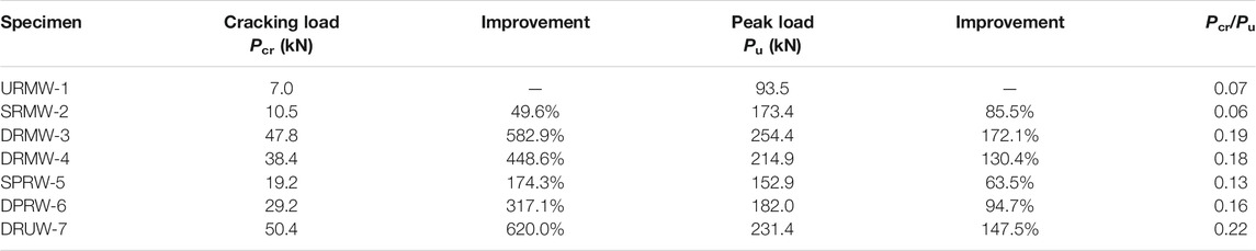
TABLE 4. Critical load values of the specimens.
Displacement ductility is an important parameter that reflects the deformation capacity of the specimen after yielding under the action of seismic force. The ductility coefficient (μ0.85) reflects the plastic deformation capacity and failure form of the specimen, which is calculated by the ultimate displacement divided by the yield displacement. A higher ductility coefficient indicates that the structure has a stronger plastic deformation ability and its failure form is a ductile failure, which results in better deformation capacity and energy dissipation capacity for the structure under earthquakes.
To accurately quantify the seismic performance of specimens, the displacements values at critical stages and the ductility coefficient of the seven specimens are listed in Table 5. In the study, the value of cracking displacement for the specimens is determined by the displacement value corresponding to the first visible crack. The yield displacement of the specimens is determined by the “Park Method.” The peak displacement was determined by the displacement value corresponding to the maximum load on the skeleton curve. The ultimate displacement was determined by the displacement value corresponding to the load drops to 85% of the peak load.
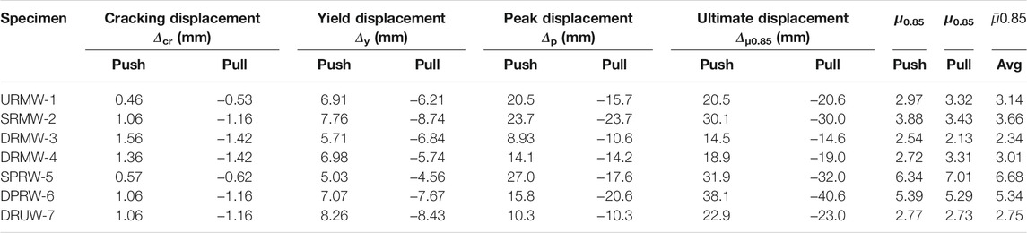
TABLE 5. Critical displacements of the specimens.
As shown in Table 5, the displacement ductility worked out at the peak load varies from 2.13 to 7.01. The minimum ductility coefficient was obtained in the double-sided full coverage specimen DRMW-3, while the maximum ductility coefficient was obtained in the single-sided coverage in piers specimen SPRW-5, 112.7% higher than that of URMW-1. Compared with specimen URMW-1, the ductility coefficients of specimens SRMW-2 and DPRW-6 increased by 16.6and 70.1%, respectively, while the specimens DRMW-3, DRMW-4, and DRUW-7 decreased by 25.5, 4.1, and 12.4%, respectively. The higher ductility coefficients of the specimens SPRW-5 and DPRW-6 were that the reinforcement in piers of the specimen could increase the stiffness ratio between the spandrels and piers, which resulted in adequate damage in spandrels and thus delayed the failure displacement. The ductility coefficients of specimens DRMW-3, DRMW-4, and DRUW-7 were lower than the specimen URMW-1. It was attributed to the stiffness being increased by the double-sided full coverage reinforcement. Hence, the cracking load was significantly increased, resulting in the advanced peak displacement. After reaching the peak displacement, the shear cracks in the coating developed faster, which led to the shear force being transferred from the coating to the masonry wall and the constructional column. Therefore, the bearing capacity of the three specimens decreased faster, and the failure of three specimens was earlier. It was worth noting that the strengthened coating of specimen DRMW-3 was thicker than that of specimen DRMW-4. Although the yield displacements of the two specimens were almost the same, the peak and failure displacements of specimen DRMW-3 were lower than that of specimen DRMW-4. It indicated that as the thickness of the HFMRPC coating increased, the peak and failure displacements were earlier to be reached, and it was more prone to brittle failure. Due to the increased yield displacement of specimen SRMW-2, the improvement in ductility coefficient was slight, and the push direction was only 3.3% higher than that of specimen URMW-1. The damaged area of specimen DRUW-7 was repaired with HFMRPC material. Due to the high ductility of the repaired material, the ductility of the repaired specimen DRUW-7 was improved by 17.5% compared with the reinforced specimen DRMW-3. It demonstrated that compared with other reinforcement methods, the way of reinforcement in piers could effectively improve the ductility of specimens.
Stiffness degradation is essentially a phenomenon that the ability to resist deformation is gradually weakened due to the accumulation of internal structural damage under the action of cyclic loading. The stiffness degradation curve reflects the changing pattern of stiffness and the difficulty of resisting deformation at each specimen stage, such as cracking, damage, and destruction. The cyclic stiffness for the first cycle can be calculated approximately by Equation. 1:
The stiffness degradation for all the tested specimens was compared in Figure 12. When cracks were observed in the walls, the secant stiffness decreased significantly. In the later stages of loading, the stiffness degradation tended to be slow, and the reduction rate slowed down for all specimens. The specimen DRMW-3 strengthened with double-sided full coverage reinforcement showed a more significant residual stiffness at the failure time. Compared with specimen URMW-1, specimen SRMW-2 improved only by 57.9%, while the peak stiffness of specimens DRMW-3, DRMW-4, SPRW-5, DPRW-6, and DRUW-7 improved by 184.1, 146.1, 145.1, 226.6, and 302.9%, respectively. Therefore, due to the strong composite restraint provided by the HFMRPC coating, each reinforcement method could enhance the stiffness of the specimens. Among them, the double-sided full coverage reinforcement had a significant effect on the improvement of stiffness, which can be enhanced with the increased thickness of the coating. The decreasing trend of the stiffness degradation curves for the specimen SPRW-5 and DPRW-6 tended to be significantly flat, which indicated that the two reinforcement methods effectively improved the brittle failure of specimens. Compared with the single-sided and double-sided strengthening of each reinforcement method, the latter significantly enhanced the peak stiffness and substantially enhanced the resistance to deformation. In summary, double-sided full coverage reinforcement can significantly improve the stiffness of masonry walls, but the improvement to brittle failure was not noticeable. The other reinforcement methods changed the damage mode from brittle damage to ductile damage and improved the stiffness of the specimens.
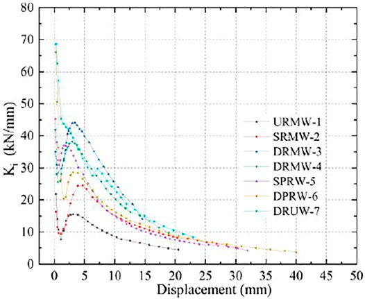
FIGURE 12. Stiffness degradation curves.
The energy dissipation in each cycle is defined by the area enclosed within the load-displacement hysteretic curve, which reflects the seismic performance of the masonry structure in the elastic-plastic state. Five energy dissipation parameters were calculated based on the hysteretic curves, including energy dissipation at yield displacement (Ey), energy dissipation at peak displacement (Ep), energy dissipation at failure displacement (Ef), single-cycle energy dissipation (Es), and cumulative energy dissipation (Ec) to evaluate the energy dissipation capacity of tested specimens at different stages. The area enclosed by the hysteretic curve of the first cycle in each horizontal displacement loading step was the single-cycle energy dissipation, and the cumulative dissipation energy was calculated by the total sum of single-cycle energy dissipation.
The single-cycle energy dissipation and the cumulative dissipation energy are plotted in Figure 13, and the energy dissipation at each stage of the specimens was compared in Table 6. The energy dissipation capacity in all stages of the specimens was significantly improved by strengthening with HFMPRC coating. The ranking for the cumulative energy dissipation using different strengthening methods: URMW-1 < DRMW-3 < DRMW-4 < DRUW-7 < SPRW-5 < SRMW-2 < DPRW-6. Since it required a larger displacement and loading cycle for the unreinforced specimen URMW-1 to dissipate the same energy, URMW-1 suffered the most severe damage. The energy dissipation at yield displacement for specimen DRMW-3 was significantly higher than that of the other strengthened specimens because the stiffness and strength were significantly increased by using double-sided full coverage reinforcement, which enhanced the areas of the hysteretic curves (i.e., energy dissipation capacity). Compared with the other specimens, although DRMW-3 consumed the most energy in single-cycle energy dissipation, it reached the peak and failure displacement at the earliest time. Hence it consumed the least cumulative dissipation energy at the peak and failure displacement. The specimen DPRW-6 that adopted the double-sided coverage in piers reinforcement showed the advantage of high ductility, and it also experienced the largest elastic-plastic deformation. Therefore, the energy dissipation of DPRW-6 in the later stage of the loading period was significantly higher than that of the other specimens.
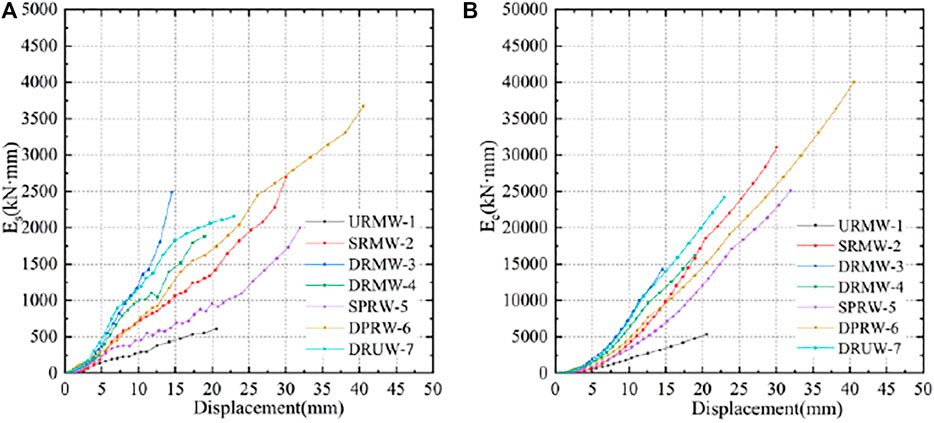
FIGURE 13. Energy dissipation (A) single-cycle dissipated energy (B) cumulative dissipated energy.
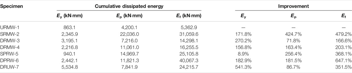
TABLE 6. Cumulative energy dissipation in each stage of the specimens.
The transmission of lateral force across the masonry wall leads to an uneven distribution of stress within that masonry wall. With the increase of lateral force, the stress distribution is changed, and the failure in masonry walls occurs when the bricks reach their shear or compression strength. In this study, the confined masonry walls with window openings are simplified and analyzed through the equivalent diagonal strut concept. The effect of masonry walls on the overall dynamic response of the masonry structure is considered by replacing the masonry wall with two diagonal struts served in compression. The maximum shear strength of the confined masonry wall with window opening is predicted based on the diagonal strut mechanism.
The total shear strength (Vmax) of the confined masonry walls with window openings retrofitted with HFMRPC coating consists of three components: the shear strength provided by masonry wall (Vman), the shear strength provided by constructional column (Vcon), and the shear strength contributed by HFMRPC coating (Vcoa and V′coa). Thus, the final shear capacity can be calculated by Equation (2):
Masonry structures are generally subjected to the combined effect of the vertical pressure caused by gravity loads and the shear forces caused by in-plane horizontal seismic action. Based on the test phenomena, the crack development pattern is shown in Figure 14. The shear resistance of the masonry wall is provided by the interaction between the brick and mortar, which includes the bond shear strength and friction. The typical stepped shear crack is approximately simplified as a single shear crack across the joint at the bottom. The vertical component of the stepped crack is in tension, and its contribution to the shear strength can thus be neglected. Referring to the code for design of masonry structures (GB 50003-2011), the shear bearing capacity of the confined masonry walls with window opening can be calculated as follows:
Where αman is the correction factor for different types of masonry and a value for brick used in the test is taken as 0.64; μ is the influence coefficient of shear-compression composite force, which can be determined according to the value of the permanent load partial factor γG; Eqs 4, 5 are used to calculate the value of μ when γG is taken as 1.2 and 1.35, respectively; f and Fmv are the design values of compressive strength and shear strength for bricks, respectively; σman is the average compressive stress in the horizontal section of the masonry wall; Aman is the horizontal cross-sectional area of the masonry wall; Rman is the reduction factor of the masonry structure.
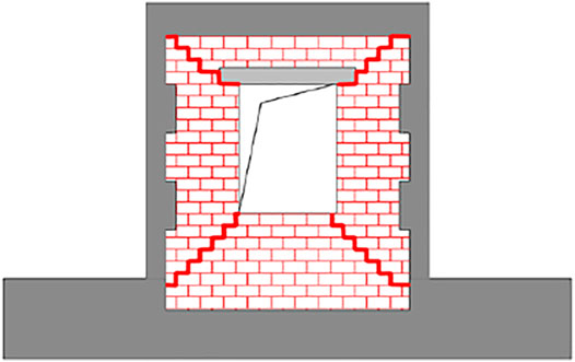
FIGURE 14. Crack pattern of specimens.
In the case of the window opening in the masonry wall, the overall shear strength of the masonry wall is directly reduced. Meanwhile, the synergistic working performance between different components in the wall is weakened, and the shear strength is thus indirectly weakened. Therefore, it is necessary to consider the reduction of the shear strength for the openings in the masonry structure by using the strength reduction factor RD1 (Al-Chaar, 2002). With the horizontal displacement increased, the elastic limit of the masonry wall is exceeded, and severe damage occurs locally. Before the specimen is repaired, the damage of mortar joints and bricks needs to be visually inspected. The corresponding damage reduction factor RD2 is used according to the damage condition to consider the effect on the bearing capacity of the repaired specimen DRUW-7. It should be noticed that the reduction factor only considers the reduction in strength of the masonry wall caused by the opening, which does not represent the possible stress distribution. Therefore, only the reduction factor is recommended to assess the bearing capacity of the overall structure. The reduction factors Rman and RD1 should be calculated as follows:
where Aoa is the area of the openings, Apa is the area of the masonry wall. For the undamaged masonry walls, the damage reduction factor RD2 is taken as 1. Based on Al-Chaar et al.’s research, the height-to-thickness ratio of specimen DRUW-7 is less than 21, and its masonry wall is subjected to moderate damage. Therefore, the value of the damage reduction factor RD2 is taken as 0.7.
If the spacing between construction columns is less than 3 m, the beneficial effect of the tie columns on the masonry structure should be taken into account. The contribution of the construction columns to the shear strength for masonry structures can be calculated as follows:
Where ft is the tensile strength of concrete cube; b and h are the section length and width of the constructional column, respectively; fyv is the tensile strength of stirrups; Asv and s are the cross-sectional area and stirrup spacing, respectively; hcon is the effective height of construction column in the calculation unit. In addition, Yang JJ et al. found that the constructional columns are commonly insufficient developed, the ultimate efficiency of the construction column should be taken into account. When the spacing between construction columns is less than 3m, the value of reduction factor λcon for shear bearing capacity of the construction columns is taken as 0.28 (Guo et al., 2019; Yang et al., 1998).
The contribution of HFMRPC coating to the shear strength can be calculated using the diagonal mechanism (Wang et al., 2021). For specimens SRMW-2, DRMW-3, DRMW-4, and DRUW-7, the HFMRPC coating can provide tensile strength to prevent diagonal cracking. Hence, the tensile strength provided by the coating can contribute to the shear strength of the masonry wall. For specimens SPRW-5 and DPRW-6, the HFMRPC coating can provide the tensile stress perpendicular to the cross-sectional direction to enhance the shear strength of the specimens. In summary, the shear strength contributed by the HFMRPC coating is calculated as follows:
where α is the tensile stress distribution factor of HFMRPC coating, and its value is taken as 0.7 for all the specimens; θ is the angle between the direction of the main crack and the horizontal. Hence, sinθ is the horizontal component of the tensile strength of the coating; the value of θ for specimens SRMW-2, DRMW-3, DRMW-4, and DRUW-7 are taken as 45°, and the value of θ for specimens SPRW-5 and DPRW-6 are taken as 70°; fcoa and Ac are the tensile strength of HFMRPC coating, and the cross-sectional area developed along the cracking direction, respectively.
Furthermore, the HFMRPC coating can also provide constraints for the construction columns (Wang et al., 2021). The shear strength provided from this restraint force for the masonry wall is calculated as follows:
Where n is the number of reinforced surfaces, tcoa is the thickness of the HFMRPC coating, h′con is equal to the one-third height of the construction column.
The shear bearing capacity of all specimens was calculated by the equations mentioned above, and the tested and calculated results are shown in Table 7. It can be seen that except for the specimen DRMW-4 (its shear strength is underestimated by 20%), the calculated results for the other specimens are generally in close agreement with the test results. The underestimation is mainly due to construction errors resulting in the thickness of the coating being thicker than 15 mm. The average value, standard deviation, and coefficient of variation of the ratio between the calculated and test results for all the tested walls are 0.90, 0.06, and 6.59%, respectively. Therefore, the simplified analytical model proposed in this study can be used to calculate the shear strength for confined masonry walls with window openings strengthened by HFMRPC coating.
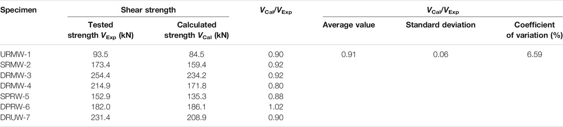
TABLE 7. Comparison of shear strength between calculated and tested values.
In this study, seven confined masonry walls with window openings were tested to investigate the effectiveness of the in-plane strengthened or repaired technologies by using HFMRPC coatings. The conclusions drawn from the experimental and theoretical results are summarized as follows:
(1) A HFMRPC mixture was selected through material tests for strengthening or repairing. In contrast to the other mixtures, the selected mixtures four exhibited the lowest compressive strength and the smallest fluidity. Meanwhile, the viscosity of mixtures four allowed it to be plastered on the surface of masonry walls by hand-trowel.
(2) The failure mode of unreinforced specimen URMW-1 was a diagonal compression failure, while the failure modes of other reinforced specimens were shear slip failure, except for the failure modes of specimens SPRW-5 and DPRW-6, which were mixed failure modes of shear failure in the spandrels and flexural failure in the piers.
(3) Compared with the control specimen URMW-1, the cracking load and peak load of the strengthened specimens were increased, among which the double-sided full coverage had the most significant effect on the increase of bearing capacity. The cracking load of the strengthened specimens was increased within the range of 49.6% (specimen SRMW-2) to 582.9% (specimen DRMW-3), while the peak loads increased from 63.5% (SPRW-5) to 172.1% (DRMW-3).
(4) The improvements of ductility coefficients were 16.6, 112.7, and 70.1% for specimens SRMW-2, SPRW-5, and DPRW-6 compared with the control specimen URMW-1. The reinforcement in piers increased the stiffness difference between the piers and spandrels, which can significantly increase the ductility of the specimens SPRW-5 and DPRW-6. However, the displacement ductility of the double-sided full coverage specimens was decreased than that of the URMW-1. The displacement ductility of specimens DRMW-3 and DRMW-4 decreased by 25.5 and 4.1%, respectively, which indicated that the peak displacement was reduced and the failure displacement was advanced by using the double-sided full coverage reinforcement method. When the coating was thicker, the ductility coefficient was reduced more significantly.
(5) The peak stiffnesses of the strengthened specimens were increased due to the strong composite restraint effect between the HFMRPC coating and specimen. The peak stiffnesses of the strengthened specimens were increased, ranging from 57.9% (SRMW-2) to 226.6% (DPRW-6) compared to the control specimen URMW-1. The energy dissipation in all stages of strengthened specimens was significantly increased compared with the URMW-1. The energy dissipation at yield displacement increased 156.8% (DRMW-4) to 270.2% (DRMW-3) except for specimen SPRW-5 (8.9%). The peak displacement energy dissipation and damage displacement energy dissipation can be enhanced within the range of 71.8–424.7% and 166.6–647.1%, respectively.
(6) Compared with the control specimen URMW-1, the cracking load, peak load, peak stiffness, and energy dissipation of the repaired specimen DRUW-7 were increased by 620.0, 147.5, 302.9, and 351.5%, respectively. Although the ductility coefficient was 12.4% lower than that of the URMW-1, it was 17.5% higher than that of the specimens DRMW-3 strengthened by double-sided full coverage.
(7) A simplified model was proposed for the shear bearing capacity of confined masonry walls with window openings strengthened by HFMRPC coating.
The original contributions presented in the study are included in the article/Supplementary Material, further inquiries can be directed to the corresponding author.
G-aL: Conceptualization, Validation, Formal analysis, Investigation, Data curation, Writing-original draft, Writing-review, and editing. XW: Methodology, Resources, Investigation, Project administration, Funding acquisition, Writing-review, and editing. ZY: Formal analysis, Data curation, Writing-original draft. L-yW: Formal analysis, Data curation. Y-wZ: Formal analysis, Data curation. G-bC: Supervision. All authors have read and agreed to the published version of the manuscript.
This study received funding from the National Natural Science Foundation of China with Grant (No. 51878395), the Key Laboratory of Building Structural Retrofitting and Underground Space Engineering of Ministry of Education “Experimental Study on Seismic Performance of Confined Masonry Walls with Window Openings Strengthened by MRPC”. The authors declare that this study received funding from Engineering Research Institute of Appraisal and Strengthening of Shandong Jianzhu University CO., LTD (No.H19230Z). The funder was not involved in the study design, collection, analysis, interpretation of data, the writing of this article or the decision to submit it for publication.
Authors L-yW, and G-bC were employed by the Engineering Research Institute of Appraisal and Strengthening of Shandong Jianzhu University CO., LTD. Author Y-wZ was employed by Shandong Dawei Design Group CO., LTD.
The remaining authors declare that the research was conducted in the absence of any commercial or financial relationships that could be construed as a potential conflict of interest.
All claims expressed in this article are solely those of the authors and do not necessarily represent those of their affiliated organizations, or those of the publisher, the editors and the reviewers. Any product that may be evaluated in this article, or claim that may be made by its manufacturer, is not guaranteed or endorsed by the publisher.
Al-Lami, K., D’Antino, T., and Colombi, P. (2020). Durability of Fabric-Reinforced Cementitious Matrix (FRCM) Composites: A Review. Appl. Sci. 10, 1714. doi:10.3390/app10051714
Augenti, N., Parisi, F., Prota, A., and Manfredi, G. (2011). In-Plane Lateral Response of a Full-Scale Masonry Subassemblage with and without an Inorganic Matrix-Grid Strengthening System. J. Compos. Constr. 15, 578–590. doi:10.1061/(ASCE)CC.1943-5614.0000193
Bisby, L., Stratford, T., Smith, J., and Halpin, S. (2011). “FRP versus Fiber Reinforced Cementitious Mortar Systems at Elevated Temperature,” in Proceeding of the 10th International Symposium on Fiber-Reinforced Polymer Reinforcement for Concrete Structures 2011, FRPRCS-10, Tampa, FL, United States, Dec 2011 (American Concrete Institute, ACI Special Publication), 863–881. doi:10.1021/acssuschemeng.7b02363
Bui, T.-L., Si Larbi, A., Reboul, N., and Ferrier, E. (2015). Shear Behaviour of Masonry walls Strengthened by External Bonded FRP and TRC. Compos. Structures 132, 923–932. doi:10.1016/j.compstruct.2015.06.057
Cai, Z., Liu, F., Yu, J., Yu, K., and Tian, L. (2021). Development of Ultra-high Ductility Engineered Cementitious Composites as a Novel and Resilient Fireproof Coating. Construction Building Mater. 288, 123090. doi:10.1016/J.CONBUILDMAT.2021.123090
Cheng, S., Yin, S., and Jing, L. (2020). Comparative Experimental Analysis on the In-Plane Shear Performance of brick Masonry walls Strengthened with Different Fiber Reinforced Materials. Construction Building Mater. 259, 120387. doi:10.1016/j.conbuildmat.2020.120387
Del Zoppo, M., Di Ludovico, M., Balsamo, A., and Prota, A. (2019a). Experimental In-Plane Shear Capacity of Clay Brick Masonry Panels Strengthened with FRCM and FRM Composites. J. Composites Construction 23, 04019038. doi:10.1061/(ASCE)CC.1943-5614.0000965
Del Zoppo, M., Di Ludovico, M., Balsamo, A., and Prota, A. (2019b). In-plane Shear Capacity of Tuff Masonry walls with Traditional and Innovative Composite Reinforced Mortars (CRM). Construction Building Mater. 210, 289–300. doi:10.1016/j.conbuildmat.2019.03.133
Deng, M., and Yang, S. (2020). Experimental and Numerical Evaluation of Confined Masonry walls Retrofitted with Engineered Cementitious Composites. Eng. Structures 207, 110249. doi:10.1016/j.engstruct.2020.110249
Ding, Y., Yu, K., and Li, M. (2022). A Review on High-Strength Engineered Cementitious Composites (HS-ECC): Design, Mechanical Property and Structural Application. Structures 35, 903–921. doi:10.1016/J.ISTRUC.2021.10.036
Dong, F. Y., Li, Z. H., Yu, J. T., Jiang, F. M., and Wang, H. P. (2022a). Shaking-Table Test on a Two-Story Timber-Framed Masonry Structure Retrofitted with Ultra-high Ductile Concrete. J. Struct. Eng. 148, 1. doi:10.1061/(ASCE)ST.1943-541X.0003164
Dong, F., Wang, H., Jiang, F., Xing, Q., and Yu, J. (2022b). In-plane Shear Behavior of Masonry Panels Strengthened with Ultra-high Ductile concrete (UHDC). Eng. Structures 252, 113609. doi:10.1016/j.engstruct.2021.113609
Dong, Z., Deng, M., Zhang, Y., Zhang, C., and Ma, P. (2020). Out-of-plane Strengthening of Unreinforced Masonry walls Using Textile Reinforced Mortar Added Short Polyvinyl Alcohol Fibers. Construction Building Mater. 260, 119910. doi:10.1016/j.conbuildmat.2020.119910
El-Diasity, M., Okail, H., Kamal, O., and Said, M. (2015). Structural Performance of Confined Masonry walls Retrofitted Using Ferrocement and GFRP under In-Plane Cyclic Loading. Eng. Structures 94, 54–69. doi:10.1016/j.engstruct.2015.03.035
Ferrara, G., Caggegi, C., Martinelli, E., and Gabor, A. (2020). Shear Capacity of Masonry walls Externally Strengthened Using Flax-TRM Composite Systems: Experimental Tests and Comparative Assessment. Construction Building Mater. 261, 120490. doi:10.1016/j.conbuildmat.2020.120490
Foraboschi, P. (2016). Effectiveness of Novel Methods to Increase the FRP-Masonry Bond Capacity. Composites B: Eng. 107, 214–232. doi:10.1016/j.compositesb.2016.09.060
Garcia-Ramonda, L., Pelá, L., Roca, P., and Camata, G. (2020). In-plane Shear Behaviour by diagonal Compression Testing of brick Masonry walls Strengthened with basalt and Steel Textile Reinforced Mortars. Construction Building Mater. 240, 117905. doi:10.1016/j.conbuildmat.2019.117905
Guerreiro, J., Ferreira, J. G., Proença, J., and Gago, A. (2018). Strengthening of Old Masonry walls for Out-Of-Plane Seismic Loading with a Cfrp Reinforced Render. Exp. Tech. 42, 355–369. 13. doi:10.1007/s40799-018-0239-0
Guo, Z., Zheng, S., Xu, Z., and Sun, W. (2019). Experimental Study on Seismic Performance of Ungrouted Confined Concrete Masonry Walls with Unbonded Tendons. Int. J. Civ Eng. 17, 333–346. doi:10.1007/s40999-017-0275-7
Kalali, A., and Kabir, M. Z. (2012). Experimental Response of Double-Wythe Masonry Panels Strengthened with Glass Fiber Reinforced Polymers Subjected to diagonal Compression Tests. Eng. Structures 39, 24–37. doi:10.1016/j.engstruct.2012.01.018
Konthesingha, K. M. C., Masia, M. J., Petersen, R. B., Mojsilovic, N., Simundic, G., and Page, A. W. (2013). Static Cyclic In-Plane Shear Response of Damaged Masonry walls Retrofitted with NSM FRP Strips - an Experimental Evaluation. Eng. Structures 50, 126–136. doi:10.1016/j.engstruct.2012.10.026
Leal-Graciano, J. M., Quiñónez, B., Rodríguez-Lozoya, H. E., Pérez-Gavilán, J. J., and Lizárraga-Pereda, J. F. (2020). Use of GFRP as Retrofit Alternative for Confined Masonry walls with Window Opening Subjected to In-Plane Lateral Load. Eng. Structures 223, 111148. doi:10.1016/j.engstruct.2020.111148
Li, V. C., and Leung, C. K. Y. (1992). Steady-State and Multiple Cracking of Short Random Fiber Composites. J. Eng. Mech. 118, 2246–2264. doi:10.1061/(asce)0733-9399(1992)118:11(2246)
Lin, Y.-W., Wotherspoon, L., Scott, A., and Ingham, J. M. (2014). In-plane Strengthening of clay brick Unreinforced Masonry Wallettes Using ECC Shotcrete. Eng. Structures 66, 57–65. doi:10.1016/j.engstruct.2014.01.043
Mercedes, L., Bernat-Maso, E., and Gil, L. (2020). Analytical Model for Masonry walls Strengthened with Vegetal Fabric Reinforced Cementitious Matrix (FRCM) Composites and Subjected to Cyclic Loads. Mater. Struct. 53, 1–14. doi:10.1617/s11527-020-01583-9
Niasar, A. N., Alaee, F. J., and Zamani, S. M. (2020). Experimental Investigation on the Performance of Unreinforced Masonry wall, Retrofitted Using Engineered Cementitious Composites. Construction Building Mater. 239, 117788. doi:10.1016/j.conbuildmat.2019.117788
Papanicolaou, C. G., Triantafillou, T. C., Karlos, K., and Papathanasiou, M. (2007). Textile-reinforced Mortar (TRM) versus FRP as Strengthening Material of URM walls: In-Plane Cyclic Loading. Mater. Struct. 40, 1081–1097. doi:10.1617/s11527-006-9207-8
Papanicolaou, C. G., Triantafillou, T. C., Papathanasiou, M., and Karlos, K. (2008). Textile Reinforced Mortar (TRM) versus FRP as Strengthening Material of URM walls: Out-Of-Plane Cyclic Loading. Mater. Structures 41, 143–157. doi:10.1617/s11527-007-9226-0
Parisi, F., Iovinella, I., Balsamo, A., Augenti, N., and Prota, A. (2013). In-plane Behaviour of Tuff Masonry Strengthened with Inorganic Matrix-Grid Composites. Composites Part B: Eng. 45, 1657–1666. doi:10.1016/j.compositesb.2012.09.068
Prota, A., Marcari, G., Fabbrocino, G., Manfredi, G., and Aldea, C. (2006). Experimental In-Plane Behavior of Tuff Masonry Strengthened with Cementitious Matrix-Grid Composites. J. Compos. Constr. 10, 223–233. doi:10.1061/(asce)1090-0268(2006)10:3(223)
Shariq, M., Abbas, H., Irtaza, H., and Qamaruddin, M. (2008). Influence of Openings on Seismic Performance of Masonry Building walls. Building Environ. 43, 1232–1240. doi:10.1016/j.buildenv.2007.03.005
Tai, J. J., Deng, J. H., Chen, F., and Wei, J. B. (2011). Characterization of Surface Rupture and Structural Damage in Hongkou Town during Wenchuan Earthquake. J. Earthquake Tsunami 05, 363–387. doi:10.1142/s1793431111001145
Van Zijl, G. P., and De Beer, L. (2019). Sprayed Strain-Hardening Cement-Based Composite Overlay for Shear Strengthening of Unreinforced Load-Bearing Masonry. Adv. Struct. Eng. 22, 1121–1135. doi:10.1177/1369433218807686
Wang, X., Li, S., Wu, Z., Bu, F., and Wang, F. (20192019). Experimental Study on Seismic Strengthening of Confined Masonry Walls Using RPC. Adv. Mater. Sci. Eng. 2019, 1–13. doi:10.1155/2019/5095120
Wang, X., Xie, Q., Wu, Z., Bu, F., and Wang, F. (2021). Experimental Study on Seismic Performance of Strengthening Masonry wall Using Hybrid Fiber-Reinforced Reactive Powder concrete. Earthquake Spectra 37, 1785–1805. doi:10.1177/8755293020988012
Keywords: confined masonry wall with window opening, hybrid-fiber modified reactive powder concrete, retrofitting, cyclic loading, seismic behavior
Citation: Liu G-a, Wang X, Yang Z, Wang L-y, Zhou Y-w and Chen G-b (2022) Experimental Study on Seismic Performance of Confined Masonry Walls With Window Openings Strengthened by Using Hybrid-Fiber Modified Reactive Powder Concrete. Front. Mater. 9:832579. doi: 10.3389/fmats.2022.832579
Received: 10 December 2021; Accepted: 03 January 2022;
Published: 14 February 2022.
Edited by:
Kequan Yu, Tongji University, ChinaCopyright © 2022 Liu, Wang, Yang, Wang, Zhou and Chen. This is an open-access article distributed under the terms of the Creative Commons Attribution License (CC BY). The use, distribution or reproduction in other forums is permitted, provided the original author(s) and the copyright owner(s) are credited and that the original publication in this journal is cited, in accordance with accepted academic practice. No use, distribution or reproduction is permitted which does not comply with these terms.
*Correspondence: Xin Wang, d2FuZ3hpbkBzZGp6dS5lZHUuY24=
Disclaimer: All claims expressed in this article are solely those of the authors and do not necessarily represent those of their affiliated organizations, or those of the publisher, the editors and the reviewers. Any product that may be evaluated in this article or claim that may be made by its manufacturer is not guaranteed or endorsed by the publisher.
Research integrity at Frontiers
Learn more about the work of our research integrity team to safeguard the quality of each article we publish.