 Tao Huang1
 Yuanchao Hu
 Yunzhu An
94% of researchers rate our articles as excellent or good
Learn more about the work of our research integrity team to safeguard the quality of each article we publish.
Find out more
ORIGINAL RESEARCH article
Front. Mater. , 04 March 2022
Sec. Polymeric and Composite Materials
Volume 9 - 2022 | https://doi.org/10.3389/fmats.2022.825694
Corrosion is an inevitable problem of metallic grounding grids. To propose an effective method avoiding the above corrosion, a new type of non-metallic grounding material was made in this paper. It is called flexible graphite composite grounding material, namely flexible graphite composite grounding material for short. It is made by high-purity flake graphite with a stranded wire hierarchical structure. And a series of experiments have been carried out to verify its feasibility as electrical grounding material, including material resistivity and its contact resistance measurement, temperature tolerance test, mechanical performance test, and scaled electrical grounding test of several typical electrical grounding grids. These experimental results all indicate that characteristics of the new flexible graphite composite grounding material can well meet practical electrical engineering requirements.
Grounding devices have always played an important role as lightning protectors in various fields, such as in power systems, communication systems, railway lines, factories, and mines (Zhang et al., 2019). Metallic material like steel, copper, and cladding steel are widely used in electrical grounding grids. However, natural corrosion of metallic grounding grids is inevitable after years of operation (Nor et al., 2006), unless expensive pure copper is used as the grounding material. Statistical corrosion data of metallic grounding grids show that serious corrosion occurs on mild steel grounding electrode surfaces after 3–5 years’ operation. A third of the mild steel electrode has already been corroded after 8–10 years’ operation (Datta et al., 2015). Besides, some anticorrosion methods performed poorly in actual operation such as galvanized steel, conductive anticorrosion glue, and some grounding resistance reduction agents. Accidents due to grounding grid corrosion usually occur, not only resulting in economic losses but also causing a serious social impact (Li et al., 2018).
Recently, researchers proposed the use of non-metallic grounding material to construct a transmission line tower grounding grid. Some non-metallic grounding products have appeared on the market, such as graphite rod and graphite grounding modules. In a previous study (Wen et al., 2016), graphite grounding modules were applied to 110–500 kV, and even ultra high-voltage (1000 kV) transmission line tower grounding projects in China. But practical excavation results found that there is still serious corrosion of internal steel in these modules. Besides, these modules are fragile and easy to fracture, which increases transport and construction difficulty. In another study (Alyami, 2019), the conductivity and permeability of a grounding conductor had an effect on its current discharge. However, this electromagnetic parameter is the material property of the grounding conductor itself and cannot be fundamentally solved by the structure optimization of the grounding grid. In previous research (Gouda et al., 2019), the researchers pointed out that the material parameters of the grounding conductor can affect the grounding resistance of the grounding grid, especially under the premise that the soil resistivity and structure have been determined. The use of grounding material with low permeability is conducive of the grounding conductor’s effective dispersion length. In another study (Zhang et al., 2021), the corrosion characteristics of several common metal grounding materials were compared and analyzed, including copper, low carbon steel, and galvanized steel, but this paper did not involve non-metallic grounding material. Researchers (Feng et al., 2015) pointed out that increasing the diameter of the grounding conductor helped increase the breakdown area of the soil layer, which was also beneficial to reduce the impact grounding impedance of the transmission line tower grounding grid. In a previous study (Sima et al., 2015), the dispersion characteristics of the grounding conductor under an impact current were studied by X-ray. The experimental results showed that increasing the diameter of the grounding conductor could increase the breakdown area of the soil. Y. Wang’s research results showed that a “needle”-shaped grounding conductor, attached to the original grounding grid, could increase the lightning current flow area. However, although this method could reduce the tower impact grounding impedance, it also increased the construction difficulty of excavation and spot welding, therefore the practical application value is low (Wang et al., 2019).
With the research of metal grounding corrosion and construction problems, some non-metallic grounding materials are beginning to be proposed. As a kind of conductor material with good conductivity, sufficient raw materials, and low price, graphite has begun to be studied in the field of the lightning protection grounding of a power system. In a previous study (Hu et al., 2014), the advantages of using graphite as grounding grids were analyzed. In another study (Huang et al., 2019), the main differences between graphite composite grounding conductors and conventional metal grounding conductors were analyzed through simulation calculation, and the practical application effects of a graphite composite grounding grid were introduced. In recent years, in order to increase the anticorrosion performance of the grounding grid, new flexible graphite composite grounding material (FGCGM) has been widely utilized in the field of power system lightning protection and grounding. In addition to China, there are few research achievements on grounding materials of power systems in other countries, especially non-metallic grounding materials. Therefore, it is important to systematically study this new non-metallic grounding material, determine the type of test category of this material, and put forward the corresponding test standards and parameters. In this paper, the structure and manufacturing process of this material are introduced, and the electrical, mechanical, temperature, and corrosion tests of FGCGM are introduced in detail. It is significant for elaborating the characteristics of the new non - metallic grounding material, and it is necessary for FGCGM to be widely applied in power systems.
Conventional grounding materials for power systems such as copper, carbon steel, or galvanized steel are prepared by smelting and electroplating processes. However, as a non-metallic material, FGCGM’s main conductive component is carbon which has strong physical and chemical stability (Hu et al., 2014); it makes the preparation of FGCGM different from traditional metal grounding materials. FGCGM is a composite material, its manufacturing process includes both a chemical process and physical composite process.
As shown in Figure 1, the preparation of FGCGM involves the following processes: 1) Crystalline flake graphite (material mesh 80, carbon content of 95%) underwent oxidation (potassium permanganate and hydrogen peroxide solution) to prepare expansible graphite. After heating at 900°C for 5–8 s to get vermicular graphite, the volume of the vermicular graphite was tens of times larger than that of flake graphite, its shape was fluffy and could be compressed by pressure (shown in Table 1). 2) The vermicular graphite was pressed into a single layer of graphite paper, and glass fiber was placed between the upper and lower layers of the graphite paper. The surface of the glass fiber was soaked with adhesive (water-soluble ethyl acrylate, ratio 1:1). The moisture of the adhesive was removed by heating for 10 s at 60–80°C, and then the sandwich graphite paper was obtained by second roll pressing. 3) The sandwich graphite paper was cut into narrow strips, and graphite wire was made by twisting, with a diameter of about 2–2.5 mm. 4) A total of 44 graphite wires were used as the inner core layer, and the outer braided layer held 24 graphite wires. A graphite composite grounding with a diameter of about 28 mm was obtained by braiding.
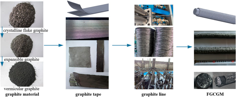
FIGURE 1. Preparation processes of flexible graphite composite electrical grounding material (FGCGM).
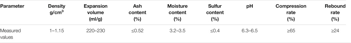
TABLE 1. Measured material parameter values of the vermicular graphite sample.
The basic characteristics of FGCGM include 1) Conductivity: The resistivity of FGCGM is 3.25 × 10⁻⁵ Ω m. And the resistivity can reach about 10–6 Ω m if conductive carbon fiber is used in FGCGM. This is approaching the resistivity of some steel. It can ensure that the lightning current and short-circuit current is dispersed timely into soil. 2) Reliable corrosion resistance: Graphite has a stable chemical property at normal temperature. It can not be corroded by any strong acid, strong alkali, or organic solvent. FGCGM has strong structure stability and reliable corrosion resistance. It can be applied to any geological condition with any resistance reducing agent (Huang et al., 2019) (Shuqi et al., 2010). 3) High flexibility: FGCGM is flexible. And it can be shaped according to practical geological conditions. When the geological condition is changed, the FGCGM will be changed together. It ensures that the soil and grounding grid join effectively. 4) Low skin effect and inductive effect: The relative permeability of FGCGM is less than 1.0. The relative permeability of steel is 636. Compared with steel, FGCGM has a lower skin effect and inductive effect under a high-frequency impulse current. On the one hand, it enhances FGCGM’S utilization rate. On the other hand, it reduces the grounding resistance (Alyami, 2019). 5) Wide range of applications: FGCGM is mainly used in electrical grounding projects, but it can be introduced into other fields, such as communication systems and petroleum systems. It is appropriate in different geological conditions. 6) Other characteristics: FGCGM is convenient for transport and use for it is flexible. The secondary use value is smaller, therefore, it can prevent grounding electrodes from being stolen. Besides, the production cost is controllable.
The physicochemical properties of FGCGM should be tested before it is utilized in practical projects. We conducted a series of performance tests in detail as follows Figure 2.
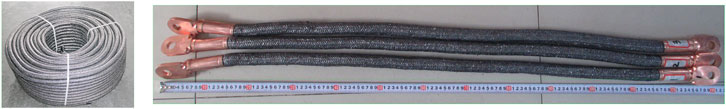
FIGURE 2. Test sample of flexible graphite composite electrical grounding material (FGCGM).
As mentioned in a previous report (He et al., 2011), material resistivity determines whether the non-metallic grounding material can be used as the most important parameter of a lightning protection grounding grid. The realization of the accurate measurement of grounding material resistivity is the primary problem of simulation calculation and simulation experiments.
The resistivity of FGCGM is measured by the four-terminal test method. It is shown in Figure 3. C1 and C2 are the current terminals; P1 and P2 are the voltage terminals; and Rx is the tested resistance. The line resistance R+ is ignored. Therefore, the resistivity of FGCGM is calculated as Eq. 1:
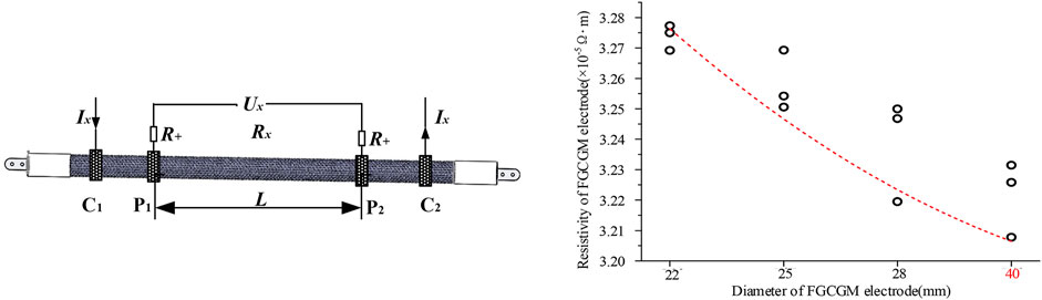
FIGURE 3. Resistivity of FGCGM with four different diameters.
In Eq. 1, r is the resistivity of FGCGM, Ω•m; Ux is the measured voltage, V; Ix is the measured current, A; d is the diameter of the FGCGM electrode, and L is the distance between the two voltage-measured positions, m.
Four types of FGCGM have been tested. Their diameters are 22, 25, 28, and 40 mm, respectively. And each type has three samples. The tested FGCGM has non-conducting fiber. The testing results are shown in Figure 3. The resistivity of FGCGM is 32.0–32.8 mΩ m. And it decreases slightly with increasing diameter. If the conducting fiber is chosen as the skeletal material, the resistivity will be much lower. According to the measurement results, the resistivity of the flexible graphite composite grounding material is one or two orders of magnitude higher than that of traditional metal steel material (Nor et al., 2005).
The connecting method between FGCGM and the tower is a noteworthy problem. Since FGCGM is a non-metallic material, welding is not appropriate. The ring crush method is proposed to connect FGCGM and the metal fitting. And the fitting is connected to the tower by a bolt or welding. The connection strength between FGCGM and the metal fitting is related to the fitting material and displacement and connecting area. The displacement rate of the metal fitting diameter is defined as Eq. 2:
Here, Φ0 is the metal ring diameter before compression, mm; Φj is the metal ring diameter after compression, mm; τ is the metal ring diameter displacement, %.
The splicing resistance is affected by metal fitting displacement. It includes the fitting resistance, ring crush resistance, and contact resistance between the ring crush and FGCGM. The four-terminal test method is employed to measure the connecting resistance Rs as shown in Figure 4. C1 and C2 are the current terminals; P1 and P2 are the voltage terminals; and Rj is the splicing resistance. Line resistance R+ is ignored. The splicing resistance is calculated as Eq. 3.
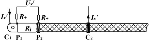
FIGURE 4. Diagram of splicing resistance measurement.
Here, r′ is the splicing resistance, Ω; Ux′ is the measured voltage, V; Ix′ is the measured current, A.
The copper ring diameter Φ0 is 32 mm. The wall thickness is 3 mm and the crush length is 80 mm. The diameter of FGCGM is 28 mm. The applied circumferential pressure is 6000 kN. Test results are shown in Figure 5. With the increasing diameter displacement rate, the splicing resistance decreases firstly, and then increases. If the diameter displacement is too large, the structure of FGCGM is damaged for inelastic deformation, resulting in a decreased crush strength between FGCGM and the metal fitting. The minimum splicing resistance is 1.7 mΩ when the diameter displacement rate is 6.25%. The proposed splicing resistance is 2 mΩ in practical use.
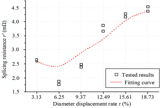
FIGURE 5. Splicing resistance of different diameter displacement rates.
The amplitude of the lightning current or short-circuit current reaches tens of kA, or even hundreds of kA. It is of high frequency. When it goes through a grounding electrode, it will produce a lot of heat and the grounding electrode temperature will be elevated dramatically. If the temperature exceeds a certain value, the mechanical property will be damaged. Besides, the mechanical property of the connect point is relatively weak, and it is easily injured by impulse currents. Therefore, the withstand impulse current level becomes an important index. Three typical impulse currents have been applied, including the lightning impulse current, oscillatory impulse current, and short-circuit impulse current (Manna and Chowdhuri, 2007) (Diaz and Silva, 2011). Three samples were used for each impulse current.
(1) Impulse withstand test with lightning impulse current
As shown in Figure 6A, the applied negative waveform of the lightning impulse current is 8/20 μs and its amplitude is 5 kA. Ten impulses are applied to each sample. The internal time between two tests is 20 min. The equivalent test circuit is shown as Figures 6B,C.
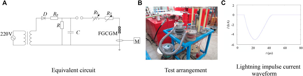
FIGURE 6. Test arrangement with lightning impulse currents.
The appearance of the testing sample was unchanged after 10 impulses. The resistance is summarized in Table 2. In Table 2, BZ1, BZ2, and BZ3 are the sample numbers; LP1P2 is the diameter of the sample; Rx1 and Rx2 are the FGCGM resistance values before and after testing; RAs1 and RAs2 are the splicing resistance values at terminal A before and after testing; RBs1 and RBs2 are the splicing resistance values at terminal B before and after testing; Δt1, Δt2, and Δt3 are the resistance change rates after testing. The FGCGM resistance and splicing resistance both increased slightly after testing. The resistance change rate was below 3%. Therefore, it is considered that a 5 kA lighting impulse current has little effect on the structure of the FGCGM electrode.
(2) Impulse withstand test with oscillatory impulse current
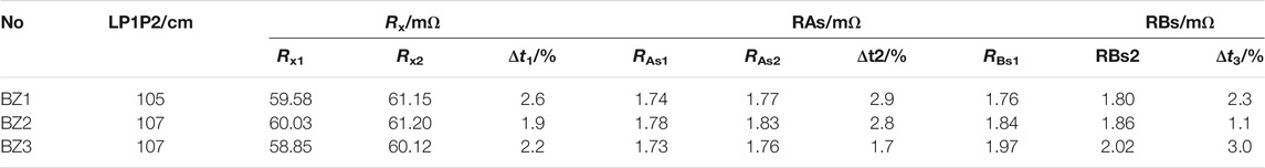
TABLE 2. Measured resistance values of the impulse withstand test with an 8/20 μs lightning current waveform.
The amplitude of the applied oscillatory impulse current is 127.5–205 kA. The internal time is 20 min. The waveform of applied impulse current is shown in Figure 7.
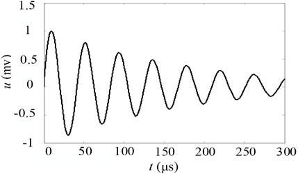
FIGURE 7. Applied oscillating impulse current (Imax = 127.5 kA, T1 = 18.4 μs in the first circle).
The measured resistance is summarized in Table 3. In Table 3, ZD1, ZD2, and ZD3 are the sample numbers; L is the length of the sample; Imax is the amplitude of the applied oscillating impulse current in the first circle; T1 is the first circle time; n is the number of applied impulse currents; Rx1 and Rx2 are the FGCGM resistance values before and after testing; RAs1 and RAs2 are the splicing resistance values at terminal A before and after testing; RBs1 and RBs2 are the splicing resistance values at terminal B before and after testing; and Δt1, Δt2, and Δt3 are the resistance change rates after testing.

TABLE 3. Measured resistance values of impulse withstand test with standard lightning current waveform.
When Imax = 127.5 kA, five impulses were applied to the FGCGM electrode. FGCGM resistance Rx was increased by 3.5%. The splicing resistance values of two terminals RAs and RBs were increased by 8.6 and 9.5%, respectively. It indicates that the applied oscillating impulse current has little influence on FGCGM. When Imax = 180kA, FGCGM resistance Rx was increased by 6.8%. The splicing resistance values of two terminals RAs and RBs were increased by 11.8 and 12.9%, respectively. When Imax = 205 kA, FGCGM resistance Rx was increased by 7.9%. The splicing resistance values of two terminals RAs and RBs were increased by 14.7 and 12.4%, respectively. The test results show that when the current amplitude is over 180 kA, the oscillating impulse current will affect the structure of the FGCGM electrode.
It should be noted that the lightning current applied is more serious than in practical cases. The above test results proved that FGCGM and the crush strength between FGCGM and the metal fitting can both withstand practical lighting impulse current.
(3) Impulse withstand test with short-circuit impulse current
The short-circuit impulse current amplitude was 26 kA. The wavelength time was 23 ms. The waveform is shown in Figure 8A. The FGCGM electrode was fixed on the Weil synthesis circuit test platform as shown in Figure 8B. The length of the FGCGM electrode was 165 cm. Two samples of DL1 and DL2 were used in tests. Each sample was tested three times. Before testing, FGCGM resistance and terminal splicing resistance were measured. The temperature of FGCGM was recorded by an infrared temperature instrument. Test results show that DL1 and DL2 resistance increased by 4.3 and 3.8% while their temperature reached 210°C. Though the splicing resistance of DL1 and DL2 increased, the increased resistance values were all less than 2.29 mΩ. Therefore, FGCGM and its fitting has appropriate stability under a short-circuit impulse current. And it meets the practical engineering requirement.
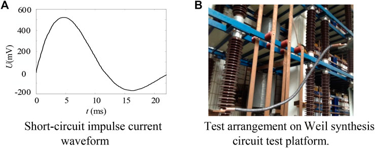
FIGURE 8. Impulse withstand test with short-circuit waveform.
A series of mechanical performance tests were conducted on FGCGM to analyze its mechanical property under external force quantitatively (Diaz and Silva, 2011). It contains bending, torsion, and tensile resistance. The diameter of FGCGM is 28 mm. The copper ring diameter is 32 mm and its wall thickness is 3 mm. Three samples were used in each test.
(1) Mechanical tests on FGCGM ontology
The bending test was arranged as shown in Figure 9A. The length of P1-P2 was 30 cm, P1-C1 and P2-C2 were of the same length: 10 cm. The neutral point of P1-P2 was selected as the bending point. One terminal of the FGCGM electrode was arranged horizontally. The other terminal was bent along the ±90° direction 10 times continuously. The three samples were numbered as 1#, 2#, and 3#. The resistance increment of P1-P2 was denoted as ΔRbend. Test results showed that ΔRbend < 0.2 mΩ. The torsion test was conducted as shown in Figure 9B. Firstly, the FGCGM electrode was placed horizontally. And then it was rotated in a clockwise direction by 720° and kept for 10 s. Finally, this was repeated in the counterclockwise direction. The resistance increment of P1-P2 was denoted as ΔRwarp. Test results showed that ΔRbend < 0.42 mΩ.
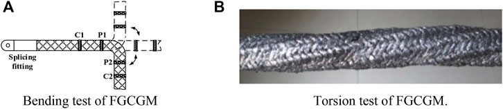
FIGURE 9. Bending and torsion tests of FGCGM.
Test results of the dynamic tensile test are shown in Figure 10A. The 1# and 2# resistance values increased with the dynamic tensile load. But 3# resistance decreased firstly and then increased. It is because the compactness of 3# is slightly poor. When the tensile load was applied, the outer layer graphite line was under axial tension. The compactness of 3# was enhanced firstly. However, the compactness enhancement was limited. With the increasing tensile load, the inner layer graphite lines were tensile to straight lines. Their distance was enlarged. Therefore, the 3# resistance increased with tensile load, which was of the same tendency as 1# and 2#. The resistance increment was below 1.6% under a 1.6 kN tensile load. The inner graphite lines were not fractured. The ultimate tensile strength of FGCGM was 23.77–24.68 kN as shown in Figure 10B. All the above results indicate that FGCGM has a good mechanical property and meets the practical engineering requirement.
(2) Mechanical tests on splicing fitting
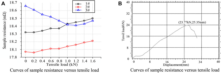
FIGURE 10. Mechanical performance test results of FGCGM.
A dynamic tensile test was conducted on the splicing fitting of different diameter displacement rates as shown in Figure 11A. Before testing, the splicing resistance was measured. The force-displacement curve is plotted in Figure 11B. The ultimate tensile strength of the connecting point is about 7.15 kN. As shown in Figure 11C, when the diameter displacement rate increased, the ultimate tensile strength increased firstly and then decreased. But the splicing resistance showed an inverse tendency which was consistent with Figure 6. Therefore, the splicing resistance is able to predict the tensile strength of splicing fitting. Test results indicate that the tensile strength of splicing fitting can exceed 7 kN with a proper diameter displacement rate.
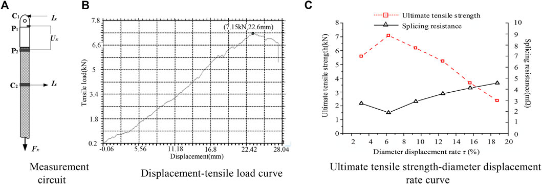
FIGURE 11. Mechanical performance test of splicing fitting.
When the lightning current or fault current goes through the FGCGM electrode, its temperature rises immediately (Sekioka et al., 2006). The large temperature rise has an effect on FGCGM resistance and the compression strength of the splicing fitting. Therefore, the high/low temperature withstand test was carried out in this section. Three FGCGM samples were used. The FGCGM diameter was 28 mm. The splicing fitting diameter was 32 mm with a wall thickness of 3 mm. The temperature coefficient of FGCGM resistance was measured by tests. And the relation between compression strength and thermal expansion coefficient was also studied by tests.
(1) Low-temperature withstand test
The three samples were numbered as L1, L2, and L3. Before testing, the FGCGM resistance and splicing resistance were measured. Temperature sensors were installed in their inner cores. The FGCGM electrodes had been placed in a low-temperature test box with a constant temperature of −40°C for 30 min. Then they were removed outside. The FGCGM dynamic resistance was recorded in real-time during their temperature return period, as shown in Figure 12. When the FGCGM temperature returned back to the primary temperature, the splicing resistance was tested again. When the FGCGM temperature was 34°C, resistance of L1 was the largest at 59.53 mΩ. It increased primary resistance by 5.1%. The splicing resistance increment was 0.02–0.04 mΩ with an increment rate of 1.1–2.2%. It reveals that the FGCGM can be applied in a low-temperature grounding grid.
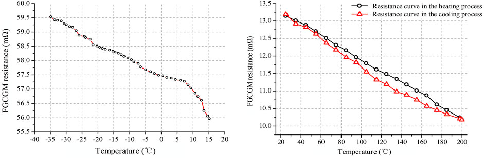
FIGURE 12. Resistance of FGCGM ontology in low and high-temperature tolerance tests.
As shown in Figure 12, FGCGM has a negative temperature characteristic, which is opposite to metal material. With the increasing temperature, the resistance of the L1 sample was decreased linearly. The resistance returned back to the primary value when L1 temperature rose up to the primary temperature. The temperature characteristic of FGCGM depends on electronic excitation and lattice thermal vibration. Electronic excitation reduces the graphite resistivity while lattice thermal vibration increases. When the graphite crystal is heated, the electron on the valence band can jump to the conduction band. The number of free electrons increases and the resistivity of graphite decreases. However, the temperature rise enlarges the lattice thermal vibration amplitude. It also increases electronic movement resistance, which increases the graphite resistivity. The effect of electronic excitation plays a leading role. Therefore, FGCGM resistance has a negative temperature characteristic in low-temperature withstand tests.
(2) High-temperature withstand test
Six testing FGCGM samples were used in the high-temperature withstand test: H1, H2, H3, H4, H5, and H6. The FGCGM resistance and splicing resistance were also measured before testing. Temperature sensors were installed in their inner cores. Two comparison experiments were developed.
a) Experiment Ι: The FGCGM electrodes H1, H2, and H3 were placed in a high-temperature test box with a constant temperature of +200°C for 30 min. And then removed. The FGCGM temperature decreased gradually from +200°C to the primary temperature.
The measured FGCGM resistance values are shown in Table 4. In Table 4, H1, H2, and H3 are the sample numbers; LP1P2 is the length of the sample; Rx1 and Rx2 are the FGCGM resistance values before and after testing; RAs1 and RAs2 are splicing resistance values at terminal A before and after testing; RBs1 and RBs2 are the splicing resistance values at terminal B before and after testing; and Δt1, Δt2, and Δt3 are the resistance change rates after the test. The resistance increment rate was less than 3%. Similar to the low-temperature withstand test results, FGCGM resistance and splicing resistance changed little before and after the high-temperature withstand test.
b) Experiment II: The FGCGM electrodes H4, H5, and H6 were placed in the high-temperature test box. The FGCGM temperature was increased gradually from primary temperature to +200°C. The electrodes were removed and their temperature decreased from +200°C to the primary temperature.
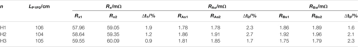
TABLE 4. Measured resistance in the high-temperature withstand experiment.
The FGCGM dynamic resistance is shown in Figure 12. When the temperature rose to +200°C, the FGCGM resistance decrement rate was about 20%. FGCGM resistance still had a negative temperature characteristic in high-temperature withstand tests. However, the dynamic resistance with increased temperature did not coincide with that of decreased temperature. The FGCGM exhibited a linear decreasing trend in the process of heating up, but increased gradually in the process of temperature decreasing, and approached the initial value. The two resistance curves were not a coincidence, on the one hand, because of the influence of measurement error. On the other hand, in the process of heating and cooling, the grounding body expands and contracts thermally and the structure of the grounding conductor subtly changes in density, which causes the deviation of the two measured curves.
In the above tests, because the grounding conductor was not smelted or press-molded, and FGCGM was made of more than 60 fine graphite wires through twisting and weaving, there were air gaps between the graphite wires, therefore under the action of tension, bending, and torsional force, subtle changes took place in the structure of the grounding conductor, these structure changes caused the contact resistance between the graphite lines. There were some measurement errors of resistance value, but the numerical value of the measurement error was very small, basically within 3%. The measurement results also shown that the structure of the test sample was stable enough under the high and low-temperature tests and mechanical properties tests. FGCGM could meet the requirements of practical grounding engineering.
In order to study the grounding characteristics of an FGCGM grounding grid, simulation experiments were carried out on a typical grounding grid (He and Zhang, 2015). The diameter of the applied FGCGM was 28 mm. There was no rain 5 days before and after the experiment. And no other grounding grid or metal pipeline was laid within 200 m. The soil resistivity was 32 Ω m.
A ditch was dug to lay a 13 m FGCGM grounding electrode. Its width was 0.8 m. Its length was 13.5 m. Its depth was 0.6 m. The FGCGM grounding electrode was placed horizontally under the ditch. Then the ditch was backfilled with uniform soil. The AC resistance of the FGCGM grounding electrode was measured by a ground resistance test set after 2 days. The average resistance was 3.27 Ω and the value was similar to the calculated value of 3.41 Ω.
The grounding grid of square frame with an extended line is shown in Figure 13A. Extended lines a, b, c, and d were of the same length at 3 m. The grid was laid down 0.6 m below the ground surface. The grounding resistance was tested from points A, B, C, and D. Each point was tested three times. The average value of grounding resistance was 2.05 Ω which was close to the simulated value of 2.32 Ω.
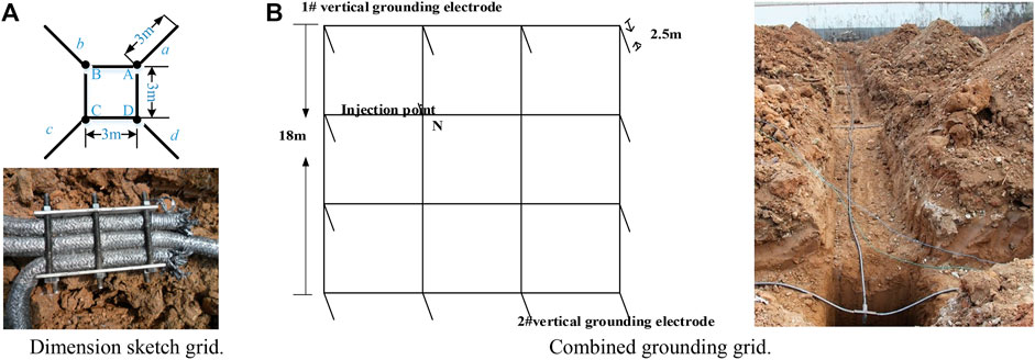
FIGURE 13. Actual grounding simulation experiments.
The combined grounding grid is shown in Figure 13B. Its embedded depth was 0.8 m. The injection point was fixed at point N. Its measured grounding resistance was 0.58 Ω while the calculated value was 0.68 Ω. The deviation was mainly caused by a tower grounding grid within 20 m of the testing site.
A scaled FGCGM grounding grid was adopted to study its impulse characteristics. The testing method was similar to metallic grounding grid in a previous research (Shuqi et al., 2010). The grounding grid was placed in a semi-sphere sand pond constructed of steel. The pond diameter was 8 m. The reflux pole on the pond surface was a flat copper strip and it was connected with a grounding grid outside. The soil in the pond was double-layered. The upper layer was sand. Its resistivity was 540 Ω m which can be changed by water content. The upper layer thickness was 0.35 m. The lower layer was red soil with resistivity of 167 Ω m. The grounding grid arrangement is shown in Figure 14A. The diameter of the FGCGM electrode was 28 mm. The embedded depth was 0.1 m. The power frequency current injection method was applied to measure its grounding resistance. The average resistance of multiple measurements was 66.72 Ω.
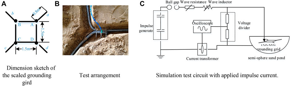
FIGURE 14. Diagram of simulation impulse test.
The circuit diagram of the simulation impulse grounding test is shown in Figure 14B. Typical impulse current and impulse voltage were measured as shown in Figure 15.
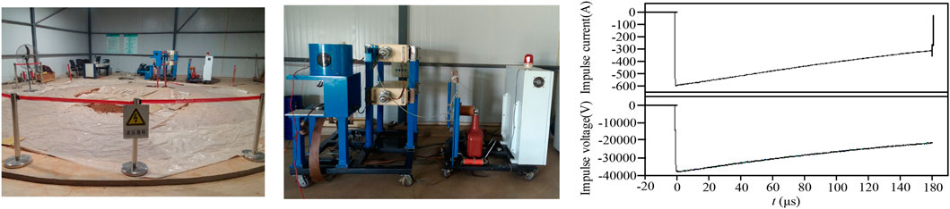
FIGURE 15. Measured waveform of impulse current and impulse voltage.
The impulse grounding resistance of the FGCGM grid was averaged as 61.89 Ω. Therefore, the impulse coefficient of the FGCGM grounding grid was 0.928. It reveals that spark discharge still occurs on FGCGM under a current of high amplitude. This is similar to metal material. The spark discharge effect is beneficial to evacuate lightning current and fault current.
A new non-metallic grounding material has been proposed in this paper. And a series of tests were conducted to study its performance. According to the above analysis, conclusions are made as follows:
(1) The resistivity of FGCGM is lower than 10–5 Ω m. And if the diameter displacement rate of splicing fitting is appropriate, the splicing resistance can be lower than 2 mΩ. The increment of FGCGM resistance and splicing resistance was lower than 3% under three typical impulse currents. The results indicate that FGCGM is stable under different impulse currents. However, when the lightning current was 180 kA, the largest resistance increment reached 12%. And this shows the structure of FGCGM was destroyed.
(2) The high/low-temperature withstand tests results show that FGCGM resistance is negatively correlated to temperature. The structure of FGCGM and the connecting point is stable under −40°C or +200°C.
(3) The mechanical property of FGCGM and the connecting point is stable, which meets the practical requirements.
(4) The simulation impulse test results of the FGCGM grounding grid show that there was a spark discharge phenomenon on FGCGM under a high impulse current. The impulse coefficient was 0.928. The test results show that the proposed FGCGM has good performance. And it is appropriate to be applied in electrical grounding engineering.
The original contributions presented in the study are included in the article/Supplementary Material, further inquiries can be directed to the corresponding authors.
TH: Conceptualization, writing-original draft preparation, and simulation; YH: Software and grounding tests; HX: Grounding test and theoretical analysis; CD: Grounding test; YA: Project administration and data arrangement; WS: Data arrangement; ZL: Grounding test; MC: Material test and data arrangement.
This manuscript was supported by Jiangsu Provincial Natural Science Foundation, China (SBK2020042717), Natural Science Foundation of China under grant (51807113), and Shandong Provincial Natural Science Foundation, China (ZR2021ME092).
Authors TH, HX, CD, WS and MC are employed by State Grid Jiangsu Electric Power Co., LTD.
The remaining authors declare that the research was conducted in the absence of any commercial or financial relationships that could be construed as a potential conflict of interest.
All claims expressed in this article are solely those of the authors and do not necessarily represent those of their affiliated organizations, or those of the publisher, the editors and the reviewers. Any product that may be evaluated in this article, or claim that may be made by its manufacturer, is not guaranteed or endorsed by the publisher.
Alyami, S. (2019). Grid Grounding Calculations for a 132-KV Substation Using Soil Backfilling. IEEE Access 7, 104933–104940. doi:10.1109/access.2019.2932447
Diaz, R., and Silva, J. (2011). Space Charge and Soil Ionization: an Electro-Kinetic Approach. IEEE Trans. Dielect. Electr. Insul. 18 (6), 2032–2039. doi:10.1109/tdei.2011.6118641
Datta, A., Taylor, R., Will, G., and Ledwich, G. (2015). An Investigation of Earth Grid Performance Using Graphene-Coated Copper. IEEE Access 3, 1042–1050. doi:10.1109/ACCESS.2015.2454295
Feng, Z., Wen, X., Tong, X., Lu, H., Lan, L., and Xing, P. (2015). Impulse Characteristics of Tower Grounding Devices Considering Soil Ionization by the Time-Domain Difference Method. IEEE Trans. Power Deliv. 30 (4), 1906–1913. doi:10.1109/tpwrd.2015.2425419
Gouda, O. E., El-Saied, T., Salem, W. A. A., and Khater, A. M. A. (2019). Evaluations of the Apparent Soil Resistivity and the Reflection Factor Effects on the Grounding Grid Performance in Three-Layer Soils. IET Sci. Meas. Tech. 13, 572–581. doi:10.1049/iet-smt.2018.5336
He, J., and Zhang, B. (2015). Progress in Lightning Impulse Characteristics of Grounding Electrodes with Soil Ionization. IEEE Trans. Ind. Applicat. 51 (6), 4924–4933. doi:10.1109/tia.2015.2427124
He, J., Zhang, B., Zeng, R., and Zhang, B. (2011). Experimental Studies of Impulse Breakdown Delay Characteristics of Soil. IEEE Trans. Power Deliv. 26 (3), 1600–1607. doi:10.1109/tpwrd.2011.2140403
Hu, Y., Ruan, J., Gong, R., Liu, Z., and Wen, W. (2014). Flexible Graphite Composite Electrical Grounding Material and its Application in Aurotower Grounding Grid of Power Transmission System. Power Syst. Technol. 38, 2851–2857. doi:10.13335/j.1000-3673.pst.2014.10.037
Huang, D., Xia, J., Ruan, J., Wu, Y., and Quan, W. (2019). Characteristics of the Flexible Graphite Grounding Material and its Engineering Application. IEEE Access 7, 59780–59787. doi:10.1109/access.2019.2913558
Li, J., Su, H., Chai, F., Xue, D.-m., Li, L., Li, X.-y., et al. (2018). Corrosion Behavior of Low-Carbon Cr Micro-Alloyed Steel for Grounding Grids in Simulated Acidic Soil. J. Iron Steel Res. Int. 25, 755–756. doi:10.1007/s42243-018-0108-1
Manna, T. K., and Chowdhuri, P. (2007). Generalised Equation of Soil Critical Electric Field EC Based on Impulse Tests and Measured Soil Electrical Parameters. IET Gener. Transm. Distrib. 1 (5), 811–817. doi:10.1049/iet-gtd:20060559
Nor, N. M., Haddad, A., and Griffiths, H. (2005). Determination of Threshold Electric Field$rm E _rm C$of Soil under High Impulse Currents. IEEE Trans. Power Deliv. 20 (3), 2108–2113. doi:10.1109/tpwrd.2005.848761
Nor, N. M., Haddad, A., and Griffiths, H. (2006). Characterization of Ionization Phenomena in Soils under Fast Impulses. IEEE Trans. Power Deliv. 21 (1), 353–361. doi:10.1109/tpwrd.2005.852352
Sekioka, S., Lorentzou, M. I., Philippakou, M. P., and Prousalidis, J. M. (2006). Current-Dependent Grounding Resistance Model Based on Energy Balance of Soil Ionization. IEEE Trans. Power Deliv. 21 (1), 194–201. doi:10.1109/tpwrd.2005.852337
Shuqi, W., Jian, L., Sen, W., and Li, Z. (2010). Grounding Grid Corrosion Diagnosis and Uncertainly Analysis of Branches. J. Comput. 5 (No.8), 1289–1295. doi:10.4304/jcp.5.8.1289-1295
Sima, W., Liu, S., Yuan, T., Luo, D., Wu, P., and Zhu, B. (2015). Experimental Study of the Discharge Area of Soil Breakdown under Surge Current Using X-Ray Imaging Technology. IEEE Trans. Ind. Applicat. 51 (6), 5343–5351. doi:10.1109/tia.2015.2448615
Wang, Y., Wang, S., Zhang, J., Li, Z., and Xu, L. (2019). Analysis of the Effect of Explosion Grounding Electrode on Grounding Resistance Reduction. J. Eng. 2019, 3251–3254. doi:10.1049/joe.2018.8407
Wen, X., Feng, Z., Lu, H., Tong, X., Lan, L., Chen, W., et al. (2016). Sparkover Observation and Analysis of the Soil under the Impulse Current. IET Sci. Meas. Tech. 10 (3), 228–233. doi:10.1049/iet-smt.2015.0082
Zhang, C., Liao, Y., Gao, X., Zhao, J., Yuan, Y., and Liao, R. (2021). Research Advances of Soil Corrosion of Grounding Grids. Micromachines 12 (5), 513. doi:10.3390/mi12050513
Keywords: flexible graphite composite electrical grounding material, resistance measurement, impulse characteristics, temperature tolerance property, mechanical property, scaled electrical grounding test
Citation: Huang T, Hu Y, Xie H, Du C, An Y, Shen W, Liu Z and Cheng M (2022) A New Flexible Graphite Composite Electrical Grounding Material. Front. Mater. 9:825694. doi: 10.3389/fmats.2022.825694
Received: 06 December 2021; Accepted: 03 February 2022;
Published: 04 March 2022.
Edited by:
Andrea Dorigato, University of Trento, ItalyReviewed by:
Yifei Wang, University of Connecticut, United StatesCopyright © 2022 Huang, Hu, Xie, Du, An, Shen, Liu and Cheng. This is an open-access article distributed under the terms of the Creative Commons Attribution License (CC BY). The use, distribution or reproduction in other forums is permitted, provided the original author(s) and the copyright owner(s) are credited and that the original publication in this journal is cited, in accordance with accepted academic practice. No use, distribution or reproduction is permitted which does not comply with these terms.
*Correspondence: Yuanchao Hu, aHV5dWFuY2hhbzMyMTFAMTI2LmNvbQ==; Yunzhu An, YW55dW56aHUyMDA2QDE2My5jb20=
Disclaimer: All claims expressed in this article are solely those of the authors and do not necessarily represent those of their affiliated organizations, or those of the publisher, the editors and the reviewers. Any product that may be evaluated in this article or claim that may be made by its manufacturer is not guaranteed or endorsed by the publisher.
Research integrity at Frontiers
Learn more about the work of our research integrity team to safeguard the quality of each article we publish.