 Meidan Liu
 Junfeng Nie
94% of researchers rate our articles as excellent or good
Learn more about the work of our research integrity team to safeguard the quality of each article we publish.
Find out more
ORIGINAL RESEARCH article
Front. Mater., 28 February 2022
Sec. Mechanics of Materials
Volume 9 - 2022 | https://doi.org/10.3389/fmats.2022.823539
In this study, 3.5 MeV Fe-ion irradiation experiments were conducted on F321 austenitic stainless-steel at different temperatures and doses. The nanohardness of the unirradiated and irradiated samples was characterized by performing nanoindentation experiments. Irradiation softening and hardening were clearly observed at 20, 100, and 300°C. However, at 300°C, after irradiation softening, the nanohardness first increased and then decreased, as opposed to the nanohardness at 20 and 100°C, which increased as the dose increased. In addition, a crystal plasticity model for a face-centered cubic single-crystal while considering irradiation-induced hardening has been proposed and numerically implemented in the user-material subroutine UMAT of ABAQUS. This was done to simulate the load-depth data of the nanoindentation experiment. The simulated results of the non-irradiated and irradiated F321 austenitic stainless-steel were compared with the experimental data. A good agreement was observed, which demonstrates the effectiveness and accuracy of the model.
F321 is an austenitic stainless-steel that is strengthened by the precipitation of TiC with the addition of Ti that is based on 304 austenitic stainless-steel. Enhanced properties, including a better ductility and resistance to intergranular corrosion, make it a structural material for nuclear reactors. The long-term exposure of nuclear reactor structural components to high temperatures and irradiation doses can result in the degradation of the mechanical properties. This includes irradiation hardening, softening, cavity swelling, and high-temperature helium embrittlement. The integrity and safety of a material affects the service life of a reactor; therefore, it is important to understand how degradation occurs.
A cascade reaction of atoms within the material is driven by the emission of neutrons, electrons, and ions. In addition, the various types of induced defects are the fundamental cause of irradiation hardening. Dislocation networks, loops, and precipitates strongly prevent the further advancement of dislocation lines on the slip surface, which act as barriers. Consequently, the greater the extended shear stress that is required to maintain the start or continued movement, the greater the hardness of the material (i.e., irradiation hardening).
Ion irradiation has also been proven to soften some materials with enhanced properties due to precipitation strengthening. Changizian et al. (2017) observed irradiation softening in a Ni-based alloy that was treated with Ni ions. The most important cause of the irradiation softening behavior of x750 Ni-based alloys, which is thought to be disordered or unstable
Nanoindentation is a simple and efficient technique for measuring the mechanical characteristics such as the nanohardness and Young’s modulus on ultra-thin samples. This is not possible with traditional measurement techniques such as uniaxial tensile, compression, torsion, and hardness tests (Oliver and Pharr, 1992). With the advantage of less damage to the measurement sample, nanoindentation techniques have recently gained a wide range of applications in metals (Schuh, 2006), ceramics (Krell and Schädlich, 2001), and nanomaterials (Díez-Pascual et al., 2015). Huang et al. (2014) adopted a nanoindentation technique to determine the mechanical properties of 316 stainless-steel that was irradiated by Xe26+ ions and identified irradiation hardening behavior in irradiated 316 SS in comparison to unirradiated 316 SS.
Numerical simulations incorporate physical mechanisms into the defect evolution based on the interaction between the defects and dislocations. This compensates for the difficulties that cannot be observed experimentally. Molecular dynamics (MD) and dislocation dynamics (DD) have studied defect-dislocation interactions at the atomic scale and mesoscopic dislocation scale, respectively, and they have derived the evolution laws of the microstructures. However, neither of these simulations can directly link the irradiation defects to the macroscopic mechanical behavior. The crystal plasticity theory integrates macroscopic plastic deformation and microscopic mechanisms to reveal the deformation of crystalline materials. An irradiation crystal plasticity finite-element method (CPFEM) was developed to simulate the mechanical properties of irradiated materials by combining the crystal plasticity model and finite element platform. Nie et al. summarized the crystal plasticity finite-element method (CPFEM) for body-centered cubic (BCC) crystals and successfully simulated the nano-indentation hardness of Chinese A508-3 steels with ion irradiation (Nie et al., 2019). Xiao et al. (2015) developed a theoretical model to determine the mechanical behavior of face-centered cubic (FCC) polycrystals with nanotwins from the perspective of crystal plasticity.
In this study, the nanoindentation technique is applied to measure the mechanical properties of F321 austenitic stainless-steel (F321 SS) that is irradiated with 3.5 MeV Fe ions at different temperatures and doses. In addition, a continuous stiffness measurement was used to obtain the depth-dependent nanohardness. We then developed a crystal plasticity model for the FCC crystals that considered the effects of the dislocations and irradiation hardening. Finally, this model was applied with the finite element platform ABAQUS (Hibbitt and Sorensen, 2005) to determine the nanohardness of F321 austenitic stainless-steel under different irradiation conditions.
Table 1 lists the chemical composition of the F321 austenitic stainless-steel. The specimens were cut into
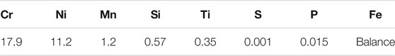
TABLE 1. Chemistry composition of F321 austenitic stainless steel (wt%).
The 3.5 MeV Fe-ion irradiation experiment was conducted on the polished specimens at 20, 100, and 300°C. The damage profiles were calculated by using the SRIM code as shown in Figure 1. The figure clearly shows that the peak damage and damage layer depth are approximately 1,000 nm and 1,600 nm, respectively. The irradiation damage level was set to 0.57, 1.71, and 2.85 dpa at every irradiation temperature. The unirradiated samples were annealed at 20, 100, and 300°C.
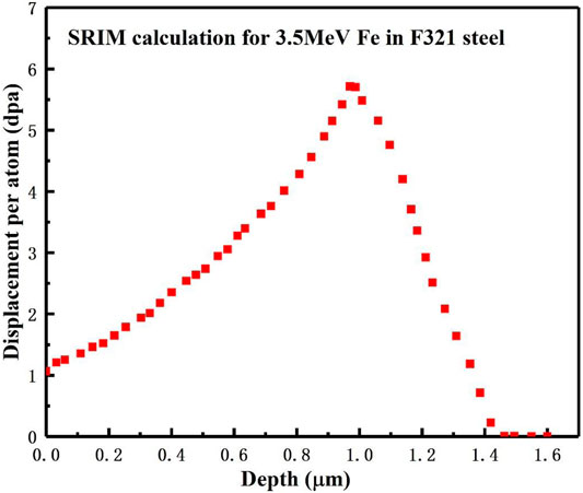
FIGURE 1. Displacement damage profile versus the depth that was calculated by the SRIM code.
A nano-indenter (G200) and Berkovoch-type indenter at Tsinghua University were applied to the irradiated specimens. The indenter was pressed in the same direction as the ion irradiation, as shown in Figure 2A. This was up to ∼2000 nm, and the irradiation region was at ∼1,600 nm. The depth dependence of the nanohardness was determined by the continuous stiffness measurement, with a strain rate and frequency of ∼0.05 s−1 and ∼45 Hz, respectively. In addition, five points were shot in each sample, followed by the average. Although the sample was irradiated at temperatures of 20, 100, and 300°C, all the nanoindentation experiments were conducted at room temperature (20°C).
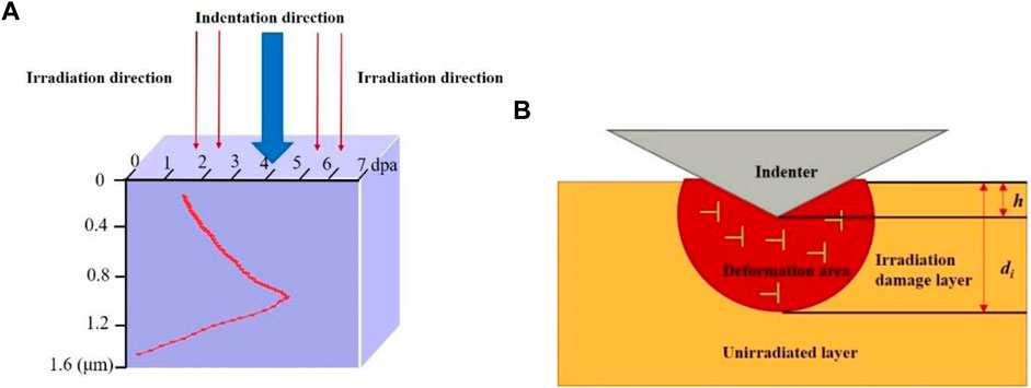
FIGURE 2. (A) Irradiation and indentation direction of the F321 austenitic stainless-steel specimen, and (B) schematic diagram of nanoindentation experiment with critical indentation depth (the area of deformation caused by the indenter being pressed into the substrate is located in the irradiation damage layer).
Figure 3 shows the nanoindentation hardness and the load that was applied by the indenter versus the depth curve by using the continuous stiffness measurement (CSM). A typical indentation size effect (ISE) of the nanoindentation can be seen in Figure 3A, in which the nanohardness decreases as the depth increases. In addition, there is another part of the
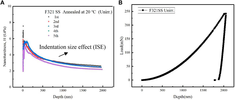
FIGURE 3. Depth dependence of (A) the nanoindentation hardness and (B) the load of the unirradiated F321 austenitic stainless steel.
The average nanohardness versus the indentation depth of F321 austenitic stainless-steel that was irradiated at different temperatures and doses is shown in Figure 4. Significant indentation size effects were also observed. It is evident that nanoindentation shows a higher nanohardness for irradiated F321 stainless-steel than the unirradiated stainless-steel, and the nanohardness increases with the dose. However, the true nanohardness is still not known due to the indentation size effects.
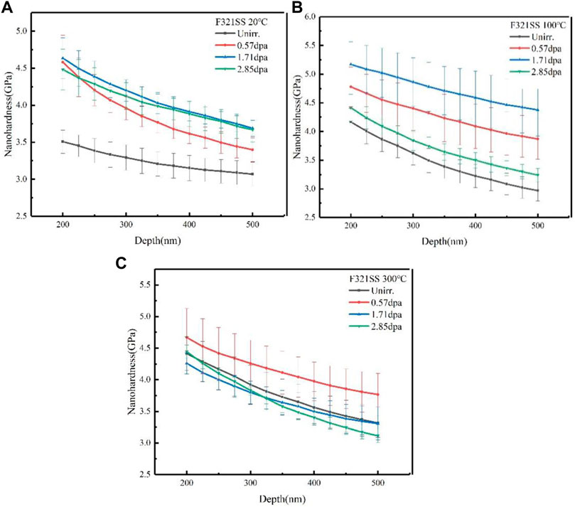
FIGURE 4. Average nanohardness versus the indentation depth of F321 austenitic stainless steel that was irradiated at (A) 20°C (B) 100°C, and (C) 300°C.
To explain the effect of ISE on the nanohardness in the continuous stiffness measurements, Nix and Gao (Kasada et al., 2011) developed a model that is based on geometrically necessary dislocations (i.e., dislocations introduced by the indentation of the indenter, and they are related to the indenter shape and indentation depth). The nanohardness depth profile that is based on the Nix-Gao model is as follows.
where H0 is the nanohardness of the material at an infinite depth, which is also known as the bulk equivalent nanohardness; h* indicates the feature depth, which is related to the shape and material of the indenter; H and h represent the nanohardness and depth, respectively, which was measured by the nanoindentation instrument. Consequently, the above equation is deformed to obtain H0.
Figure 5 shows the
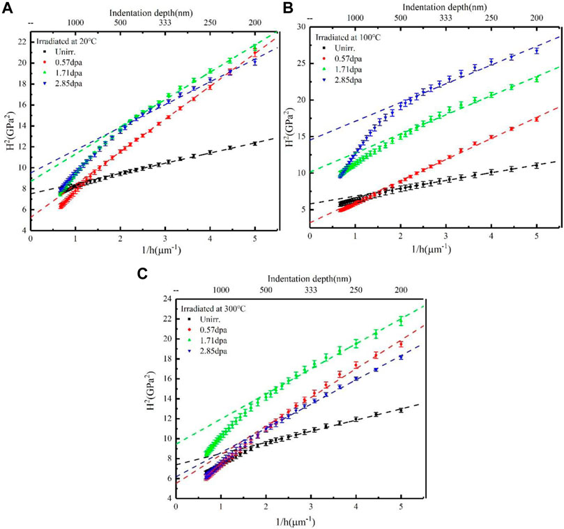
FIGURE 5.
We fitted the square of the nanohardness between 200 and 500 nm versus the reciprocal of the depth. As expected from Eq. 2, the square root of the intercept of the fitted equation was calculated as the bulk equivalent hardness H0. Table 2 shows the bulk equivalent hardness H0 for the different irradiation conditions.
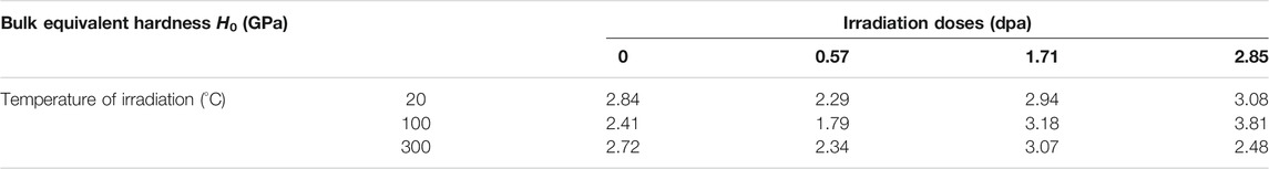
TABLE 2. Bulk equivalent hardness H0 of F321 stainless-steel at different irradiation temperatures and doses.
Figure 6 shows the irradiation dose dependence of the Bulk equivalent hardness H0 of F321 stainless-steel at different temperatures. Note that the nanohardness of the specimens that was irradiated at 0.57 dpa is lower than the unirradiated specimens, whether at 20, 100, or 300°C. Irradiation softening is interpreted as the precipitated phase TiC that is disrupted by incident iron ions, which strengthens the mechanical properties by blocking the dislocation expansion channels, such as the resistance to high temperature creep and corrosion resistance. Furthermore, the effect of a disordered TiC on the reduction of the hardness is greater than the hardening effect due to irradiation defects (Sencer et al., 2001; Changizian et al., 2017).
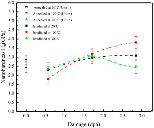
FIGURE 6. Irradiation dose dependence of the Bulk equivalent hardness H0 of F321 stainless-steel at different temperatures.
After the dose was increased, the nanohardness increased rapidly and then it decreased as the dose increased. This is described in the literature for gradual saturation (Zinkle et al., 1993). At a temperature of 100°C, the trend of increasing the nanohardness with an increasing dose was greater than that at 20°C. Vacancies and interstitials are more concentrated and diffuse at elevated temperatures, which increase the intensity of the point defects that are trapped at defect sinks, and increases the density and size of the dislocation loops (Was et al., 2002; Deo et al., 2008). However, the nanohardness increased and then decreased at 300°C, which may be due to the absorption of the point defects by the dislocations at higher temperatures; thus, resulting in dislocation creep that facilitates dislocation recovery. Meanwhile, high radiation doses promote the formation of Cr2C3 precipitates, which expand the intergranular chromium-poor zone (Liu et al., 2020).
The plasticity theory explains the deformation rules of the crystal materials by blending macroscopic plasticity with microscopic deformation. Rice (Hill and Rice, 1972) and Hill (Hill, 1966) developed a mathematical description of the geometry and kinematics of the crystal plasticity deformation. In the crystal plasticity theory, the gradient tensor
where
In this study, Hill and Rice (Hill and Rice, 1972)’s constitutive equation for the crystal elasticity was used.
where
In this study, the shear strain rate was obtained from the thermal activation theory (Busso, 1990), which was combined with the Orowan formula (Orowan, 1940).
According to the classical dislocation theory, the nature of plastic deformation in crystals is that the dislocations overcome the resistance to slip in the lattice under external forces. The decomposition of the shear stress from Schmid’s law is described as follows.
Similarly, the slip resistance is another important factor that affects the slip state of the slip systems. The dislocation lines are pinned by irradiation defects that are induced by incident particles during plastic deformation, which blocked the further movement of dislocations. As a result, the interaction between the irradiation defects and dislocations and the evolution of the defects are responsible for increasing the slip resistance, which results in irradiation hardening. Frank loops are only discussed in this study, and other irradiation defects, such as cavities or precipitates, were not considered for simplification.
By summarizing the above features, the slip resistance for the αth slip system can be expressed as follows (Taylor, 1938; Hüsken and Brouwers, 2008; Nie et al., 2017).
where G represents the shear modulus, b is the Burgers vector,
In our model, we considered the evolution of the dislocations, which includes the dislocation proliferation and annihilation, and capturing mobile dislocations into immobile dislocations (Essmann and Mughrabi, 1979; Arsenlis and Parks, 2002; Austin and McDowell, 2011).
where
The evolution of the dislocation loops and their interaction with dislocations, such as the irradiation dose, temperature, and chemical composition, are extremely complicated and are affected by several factors. Thus, this study only considers the influence of the irradiation dose on the density and size of the dislocation loops. The density and diameter of the dislocations are approximately proportional to the square root of the dose at a low dose level, and then they gradually saturate to a stable value (Deo et al., 2008).
where A and B are used to satisfy the simulated value and experimental observation of the density and diameter of the dislocation loops.
The number and diameter of the dislocation loops after irradiation can be determined by using Eqs 12, 13. However, a significant interaction occurs with the dislocation loop when the dislocation line plastically slips on the slip surface. Therefore, the evolution of dislocations and dislocation loops must be accounted for in this model. The annihilation rate of the dislocation loops was defined by Patra (Patra and McDowell, 2012) as follows.
where c is the annihilation index, and
In Figure 7, the established three-dimensional nanoindentation finite element geometric model is shown, which includes a variable deformation matrix and a rigid indenter, since the Berkovich indenter is made of diamond. In the matrix model, R and H are both equal to 10
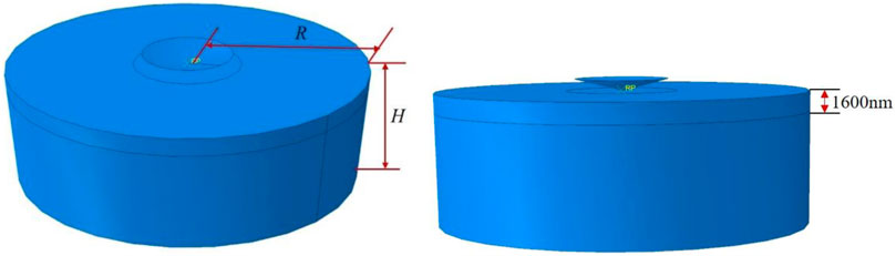
FIGURE 7. Model for the nanoindentation experiment.
In particular, the matrix model is divided into two layers: an irradiated layer with a thickness of 1,600 nm and an unirradiated layer at the bottom. The irradiation dose of the irradiated layer was determined as the average dose based on the results of the irradiation damage and the depth simulated by the SRIM code. As demonstrated in Figure 8, when the peak dose of the incident Fe ions is approximately 5.7 dpa, the average dose is approximately 2.64 dpa.
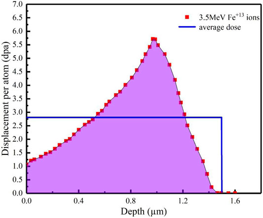
FIGURE 8. Peak irradiation damage dose of ∼5.7 dpa and the average dose calculated by the SRIM code.
A C3D8 mesh type was used to divide the matrix model and refine the local mesh of the contact area between the matrix and the indenter to represent the contact behavior and indentation morphology more accurately. As demonstrated from the comparison results in Figure 9B, there is a slight impact on the mesh number on the loading-depth curve. In the subsequent calculations, a 0.005
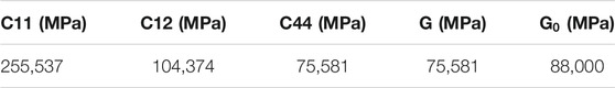
TABLE 3. Constitutive modulus.
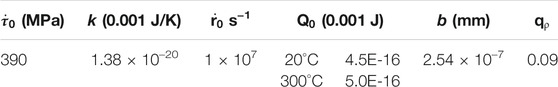
TABLE 4. Shear strain rate related parameters.
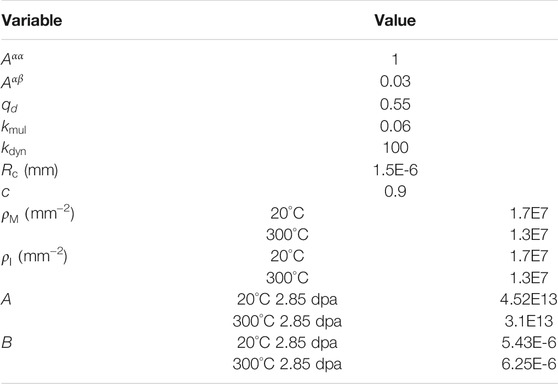
TABLE 5. Irradiation hardening parameters.
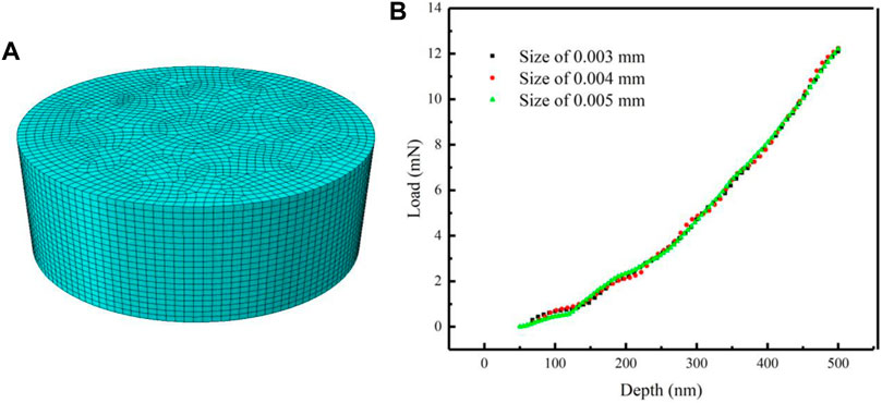
FIGURE 9. (A) Matrix model of the C3D8 mesh, and (B) the loading-depth curve of the different element sizes.
In summary, we developed a crystal plasticity model that fully incorporates irradiation-induced defects and is capable of describing the face-centered cubic crystal of F321 austenitic stainless-steel. This was successfully implemented through the subroutine UMAT in the finite element software program ABAQUS. The details of the numerical implementation are presented in the Appendix.
According to the results of the nanoindentation experiment that were mentioned above, the irradiated softening phenomenon occurs when the hardness of F321 austenitic stainless-steel decreases significantly in comparison to the 1.71 dpa irradiated sample and the unirradiated sample. In this study, irradiation softening was not considered, and the focus was on the re-realization of irradiation hardening. In addition, only two irradiation conditions at room temperature and a high temperature were studied to simplify the calculation. As a result, we only simulated the results of the nanoindentation experiments on a F321 austenitic stainless-steel sample that was irradiated at room temperature (20°C) and a high temperature (300°C) with a dose of 2.85 dpa.
The grain size of the F321 austenitic stainless-steel that was tested in the nanoindentation experiment was greater than three, and the grain size was ∼127
Figure 10 shows the load-depth curve of the nanoindentation experiment and a simulation of five crystal orientations under non-irradiated conditions at 20°C. It can be observed that there are differences between the crystal orientations, and the load of the [111] crystal orientation is the largest due to the close packing direction. The average load of the five crystal orientations is in good agreement with the experimental results.
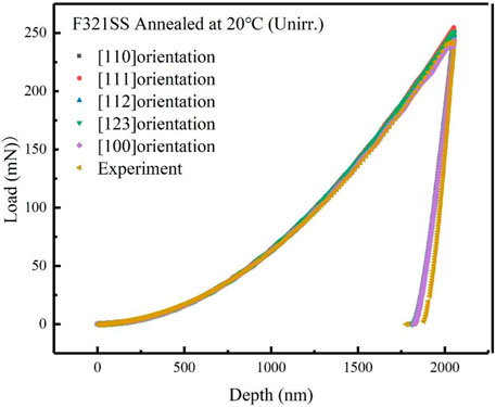
FIGURE 10. Depth dependence of the load for the simulation results of the five typical crystal orientations for unirradiated F321 austenitic stainless-steel at 20°C.
Due to the size effect, for the irradiated samples, only loads with a depth of 200–500 nm were considered. The simulation of the load distribution with a depth of F321 austenitic stainless-steel that was irradiated at 20 and 300°C was compared with the experimental result as demonstrated in Figures 11, 12. The simulated and experimental values are based on the average of the results of the five crystal orientations that are assigned to the model matrix and the five indentation points of the indenter on the surface of the F321 austenitic stainless-steel sample. As demonstrated, a good conformity is obvious. It is worth emphasizing that in our simulation, the number density and the diameter of the dislocation loops inside the F321 austenitic stainless-steel under an irradiation dose of 2.85 dpa at 20°C were set to 5.2E22 m−3 and 6.2 nm, respectively. This is consistent with the experimental observations. In addition, the number density of the dislocation loops at an irradiation temperature of 300°C was reduced in comparison to that at 20°C, while the diameter increased with an increase in the temperature, 3.6E22 m−3, 7.2 nm. The trend of the dislocation ring density and the diameter with the temperature is reasonable. According to the results that were presented by Jin (Jin et al., 2017), who analyzed radiation defects in austenitic stainless-steel that was irradiated with Fe ions at 200, 300, and 400°C, the density and size of the Frank loops decreased and increased, respectively, with the irradiation temperature. Furthermore, Was (Was, 1999) also found similar results, in which two iron-based alloys (Fe-20Cr-9Ni and Fe-20Cr-24Ni) were irradiated with 3.2 MeV H+. Was observed that the loop size increased sharply with the irradiation temperature and the number density dropped sharply.
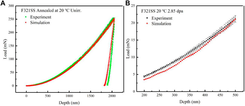
FIGURE 11. Result of the load distribution with the depth of (A) unirradiated F321 austenitic stainless-steel, (B) a 2.85 dpa dose for F321 austenitic stainless-steel that was irradiated at 20°C.
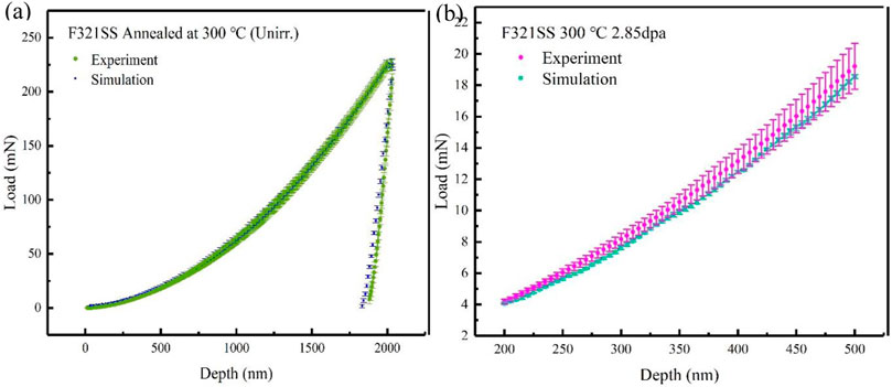
FIGURE 12. Comparison of the experiment and simulation for the load trend with a depth of (A) unirradiated F321 austenitic stainless-steel, and (B) irradiated F321 austenitic stainless-steel with a 2.85 dpa dose at 300°C.
Figure 13 shows the Mises stress contours when the indenter is pressed into the matrix material at a depth of 500 nm. A non-uniform deformation is observed in all five crystal orientations.
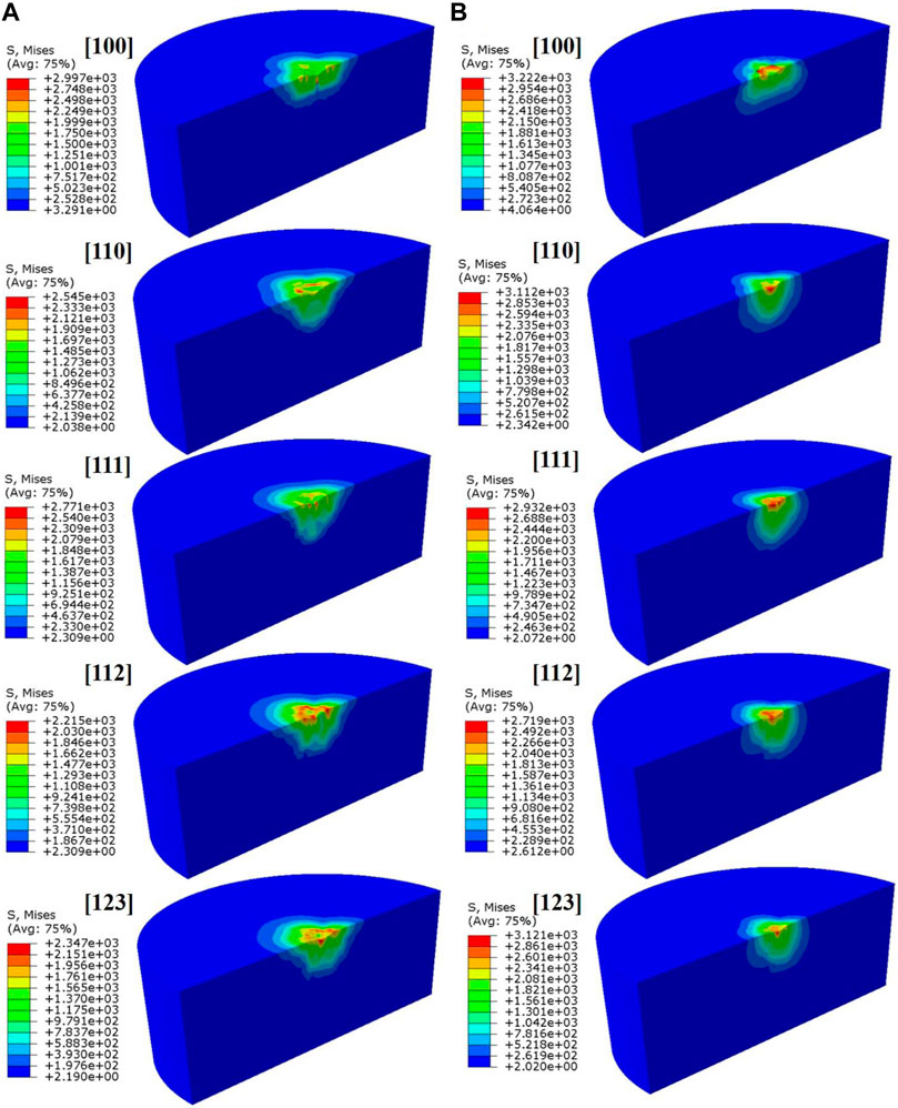
FIGURE 13. Mises stress contours with a dose of 2.85 dpa at (A) 20°C and (B) 300°C.
Typically, in the classical dislocation theory, dislocations are hindered by randomly distributed microstructure components produced by irradiation. These components act as barriers under shear stress and the dislocation is unable to continue moving. Therefore, extended shear stress is required to cause the change in mechanical properties. The nanohardness of the material is strongly related to the distribution of dislocations and dislocation loops. As Figure 14 shows, under different temperatures and irradiated conditions, dislocations, and dislocation loops changes. Although the increase in the concentration and diffusion of interstitials and vacancies promotes the formation of dislocations at higher temperatures, the faster annihilation rate results in the recovery of dislocations and the reduction of dislocation density. From Figures 14A,B, the dislocation density at 300°C is lower than 20°C. According to Eq. 10, the slip resistance is positively related to the dislocation density, and due to the recovery of dislocations, the nanohardness of F321 austenitic stainless steel decreases at 300°C. After irradiation, the diameter and density of dislocation loops are affected by temperature. Was et al. (Was, 1999) exposed several austenitic stainless steels to different radiation temperatures and doses and discovered that the diameter of dislocation loops increases with increasing temperature, but the density decreases. Figure 14C presents the product of the diameter and density of the dislocation loops at 20 and 300°C. At 300°C, the increase in dislocation loop diameter is not as large as the decrease in dislocation loop density, so the decrease in
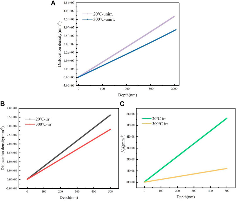
FIGURE 14. The dislocation density or dislocation loops changes with depth (A) under unirradiated conditions with the depth of 2000 nm (B) under irradiated conditions with the depth of 500 nm (C) the product of the diameter and density of the dislocation loops (
Here, F321 austenitic stainless-steel was irradiated by 3.5 MeV Fe ions at irradiation doses of 0.57, 1.71, and 2.85 dpa at 20, 100, and 300°C, respectively. The continuous stiffness measurement method of the nanoindentation experiment was applied to characterize the nanohardness of the unirradiated and irradiated samples. The main conclusions can be expressed as follows.
• The Nix-Gao model was used to analyze the nanohardness-depth data while excluding the influence of the size effect (ISE) from which the Bruker equivalent hardness H0 was calculated.
• It was observed that irradiation softening had occurred. The nanohardness of the specimens that were irradiated at 0.57 dpa was much lower than the unirradiated specimens, whether at 20, 100, or 300°C.
• Subsequently, with the increase in the dose, the nanohardness increased rapidly, and the phenomenon of irradiation hardening was obvious. However, higher irradiation doses resulted in a decrease in the nanohardness at 300°C.
In our manuscript, we focus on exploring the effects of irradiation dose on F321 austenitic stainless steel at the nanoscale. In the future, we will carry out TEM experiments to analyze the microscopic morphology after irradiation, and will further explore the relationship between the microscopic morphology and the macroscopic properties of irradiation (Maruschak et al., 2013).
In addition, we proposed a model that is based on the laws of physics that considers irradiation hardening that is caused by irradiation defects (dislocation loops) through the CPFEM.
• Our crystal plasticity model describes how the dislocation density and dislocation loops evolve in F321 austenitic stainless-steel with a FCC structure, and it was numerically implemented in the user-material subroutine UMAT of ABAQUS.
• The load-depth curve was successfully realized and verified with the experimental results for unirradiated and irradiated conditions at a low temperature and high temperature. A comparison of the results showed a good consistency.
• It is worth noting that the proposed model is a multi-scale model that combines mesoscale crystal plasticity and macroscopic mechanical properties. This is valuable for studying the irradiation-induced hardening of the structural components that belong to nuclear power plants.
The raw data supporting the conclusion of this article will be made available by the authors, without undue reservation.
ML was mainly responsible for the work and writing of the paper, JN launched the guidance work on the paper, and PL made relevant revisions.
The support of National Key R&D Plan of China under Grant No. 2020YFB1901600, National Science and Technology Major Project of China under Grant No. 2017ZX06902012 and No. 2017ZX06901024 are gratefully acknowledged.
The authors declare that the research was conducted in the absence of any commercial or financial relationships that could be construed as a potential conflict of interest.
All claims expressed in this article are solely those of the authors and do not necessarily represent those of their affiliated organizations, or those of the publisher, the editors and the reviewers. Any product that may be evaluated in this article, or claim that may be made by its manufacturer, is not guaranteed or endorsed by the publisher.
Arsenlis, A., and Parks, D. M. (2002). Modeling the Evolution of Crystallographic Dislocation Density in crystal Plasticity. J. Mech. Phys. Sol. 50 (9), 1979–2009. doi:10.1016/S0022-5096(01)00134-X
Austin, R. A., and McDowell, D. L. (2011). A Dislocation-Based Constitutive Model for Viscoplastic Deformation of Fcc Metals at Very High Strain Rates. Int. J. Plasticity 27 (1), 1–24. doi:10.1016/j.ijplas.2010.03.002
Busso, E. P. (1990). Cyclic Deformation of Monocrystalline Nickel Aluminide and High Temperature Coatings. Massachusetts Institute of Technology.
Changizian, P., Lu, C., Yao, Z., and Wang, L. M. (2017). Indentation Behaviour of Ion-Irradiated X-750 Ni-Based Superalloy. Phil. Mag. Lett. 97 (3), 101–109. doi:10.1080/09500839.2017.1288941
Deo, C., Tomé, C., Lebensohn, R., and Maloy, S. (2008). Modeling and Simulation of Irradiation Hardening in Structural Ferritic Steels for Advanced Nuclear Reactors. J. Nucl. Mater. 377 (1), 136–140. doi:10.1016/j.jnucmat.2008.02.064
Díez-Pascual, A. M., Gómez-Fatou, M. A., Ania, F., and Flores, A. (2015). Nanoindentation in Polymer Nanocomposites. Prog. Mater. Sci. 67, 1–94. doi:10.1016/j.pmatsci.2014.06.002
Essmann, U., and Mughrabi, H. (1979). Annihilation of Dislocations during Tensile and Cyclic Deformation and Limits of Dislocation Densities. Philosophical Mag. A 40 (6), 731–756. doi:10.1080/01418617908234871
Hashimoto, N., Hunn, J. D., Byun, T. S., and Mansur, L. K. (2003). Microstructural Analysis of Ion-Irradiation-Induced Hardening in Inconel 718. J. Nucl. Mater. 318, 300–306. doi:10.1016/S0022-3115(03)00013-8
Hill, R. (1966). Generalized Constitutive Relations for Incremental Deformation of Metal Crystals by Multislip. J. Mech. Phys. Sol. 14 (2), 95–102. doi:10.1016/0022-5096(66)90040-8
Hill, R., and Rice, J. R. (1972). Constitutive Analysis of Elastic-Plastic Crystals at Arbitrary Strain. J. Mech. Phys. Sol. 20 (6), 401–413. doi:10.1016/0022-5096(72)90017-8
Huang, H. F., Li, J. J., Li, D. H., Liu, R. D., Lei, G. H., Huang, Q., et al. (2014). TEM, XRD and Nanoindentation Characterization of Xenon Ion Irradiation Damage in Austenitic Stainless Steels. J. Nucl. Mater. 454 (1–3), 168–172. doi:10.1016/j.jnucmat.2014.07.033
Hüsken, G., and Brouwers, H. (2008). “Air Purification by Cementitious Materials: Evaluation of Air Purifying Properties,” in International Conference on Construction and Building Technology (Malaysia: Kuala Lumpur).
Jin, H.-H., Ko, E., Lim, S., Kwon, J., and Shin, C. (2017). Effect of Irradiation Temperature on Microstructural Changes in Self-Ion Irradiated Austenitic Stainless Steel. J. Nucl. Mater. 493, 239–245. doi:10.1016/j.jnucmat.2017.06.019
Kasada, R., Takayama, Y., Yabuuchi, K., and Kimura, A. (2011). A New Approach to Evaluate Irradiation Hardening of Ion-Irradiated Ferritic Alloys by Nano-Indentation Techniques. Fusion Eng. Des. 86 (9–11), 2658–2661. doi:10.1016/j.fusengdes.2011.03.073
Krell, A., and Schädlich, S. (2001). Nanoindentation Hardness of Submicrometer Alumina Ceramics. Mater. Sci. Eng. A. 307 (1–2), 172–181. doi:10.1016/S0921-5093(00)01818-9
Liu, X., Gigax, J. G., Poplawsky, J. D., Guo, W., Kim, H., Shao, L., et al. (2020). Radiation Response of a Fe-20Cr-25Ni Austenitic Stainless Steel under Fe2+ Irradiation at 500°C. Materialia 9, 100542. doi:10.1016/j.mtla.2019.100542
Liu, Y., Varghese, S., Ma, J., Yoshino, M., Lu, H., and Komanduri, R. (2008). Orientation Effects in Nanoindentation of Single crystal Copper. Int. J. Plasticity 24 (11), 1990–2015. doi:10.1016/j.ijplas.2008.02.009
Maruschak, P. O., Okipnyi, I. B., Poberezhnyi, L. Y., and Maruschak, E. V. (2013). Study of Heat-Resistant Steel Strain Hardening by Indentation. Metallurgist 56 (11), 946–951. doi:10.1007/s11015-013-9680-6
Narayanan, K. R., Subbiah, S., and Sridhar, I. (2011). Indentation Response of Single-crystal Copper Using Rate-independent crystal Plasticity. Appl. Phys. A. 105 (2), 453–461. doi:10.1007/s00339-011-6618-3
Nie, J., Liu, Y., Xie, Q., and Liu, Z. (2019). Study on the Irradiation Effect of Mechanical Properties of RPV Steels Using crystal Plasticity Model. Nucl. Eng. Tech. 51 (2), 501–509. doi:10.1016/j.net.2018.10.020
Nie, J., Tang, Z., and Zhang, H. (2017). Crystal Plasticity Constitutive Model for BCC Based on the Dislocation Density. J. Tsinghua Univ. (Natural Sci. Edition) 057 (007), 780–784. (in Chinese).
Oliver, W. C., and Pharr, G. M. (1992). An Improved Technique for Determining Hardness and Elastic Modulus Using Load and Displacement Sensing Indentation Experiments. J. Mater. Res. 7 (6), 1564–1583. doi:10.1557/JMR.1992.1564
Orowan, E. (1940). Problems of Plastic Gliding. Proc. Phys. Soc. 52 (1), 8–22. doi:10.1088/0959-5309/52/1/303
Patra, A., and McDowell, D. L. (2012). Crystal Plasticity-Based Constitutive Modelling of Irradiated Bcc Structures. Phil. Mag. 92 (7), 861–887. doi:10.1080/14786435.2011.634855
Peirce, D., Shih, C. F., and Needleman, A. (1984). A tangent Modulus Method for Rate Dependent Solids. Comput. Structures 18 (5), 875–887. doi:10.1016/0045-7949(84)90033-6
Schuh, C. A. (2006). Nanoindentation Studies of Materials. Mater. Today 9 (5), 32–40. doi:10.1016/S1369-7021(06)71495-X
Sencer, B., Bond, G. M., Garner, F. A., Hamilton, M. L., Maloy, S. A., Sommer, W. F., et al. (2001). Correlation of Radiation-Induced Changes in Mechanical Properties and Microstructural Development of Alloy 718 Irradiated with Mixed Spectra of High-Energy Protons and Spallation Neutrons. J. Nucl. Mater. 296 (1–3), 145–154. doi:10.1016/S0022-3115(01)00517-7
Wang, Y., Raabe, D., Klüber, C., and Roters, F. (2004). Orientation Dependence of Nanoindentation Pile-Up Patterns and of Nanoindentation Microtextures in Copper Single Crystals. Acta Materialia 52 (8), 2229–2238. doi:10.1016/j.actamat.2004.01.016
Was, G. S., Busby, J. T., Allen, T., Kenik, E. A., Jensson, A., Bruemmer, S. M., et al. (2002). Emulation of Neutron Irradiation Effects with Protons: Validation of Principle. J. Nucl. Mater. 300 (2–3), 198–216. doi:10.1016/S0022-3115(01)00751-6
Was, G. S. (1999). Microchemistry and Microstructure of Proton-Irradiated Austenitic Alloys: toward an Understanding of Irradiation Effects in LWR Core Components. J. Nucl. Mater. 270 (1–2), 96–114. doi:10.1016/S0022-3115(98)00897-6
Xiao, X., Terentyev, D., Yu, L., Song, D., Bakaev, A., and Duan, H. (2015). Modelling Irradiation-Induced Softening in BCC Iron by crystal Plasticity Approach. J. Nucl. Mater. 466, 312–315. doi:10.1016/j.jnucmat.2015.08.017
Zinkle, S. J., Maziasz, P. J., and Stoller, R. E. (1993). Dose Dependence of the Microstructural Evolution in Neutron-Irradiated Austenitic Stainless Steel. J. Nucl. Mater. 206 (2–3), 266–286. doi:10.1016/0022-3115(93)90128-l
Implementing subroutines in an incremental form are beneficial. An analysis of the rate-dependent solids by using the tangent modulus in this subroutine was adopted in Peirce’s work (Peirce et al., 1984). The shear strain increment over time is considered as follows.
The above expression is changed to a linear form as follows.
The value of the integral parameter
Moreover, the shear strain increment is obtained smoothly as shown below.
where
In addition,
Combining Eqs 14, A1–A3,
Therefore, by substituting Eqs A4–A9 into Eq. A3, the final shear strain increment expression
Keywords: F321 austenitic stainless-steel, nanoindentation experiments, irradiation softening, irradiation hardening, crystal plasticity model
Citation: Liu M, Nie J and Lin P (2022) Irradiation Effect on F321 Austenitic Stainless-Steel: Nanoindentation and Modeling With the Crystal Plasticity Method. Front. Mater. 9:823539. doi: 10.3389/fmats.2022.823539
Received: 27 November 2021; Accepted: 25 January 2022;
Published: 28 February 2022.
Edited by:
Dongchan Jang, Korea Advanced Institute of Science and Technology, South KoreaReviewed by:
Pavlo Maruschak, Ternopil Ivan Pului National Technical University, UkraineCopyright © 2022 Liu, Nie and Lin. This is an open-access article distributed under the terms of the Creative Commons Attribution License (CC BY). The use, distribution or reproduction in other forums is permitted, provided the original author(s) and the copyright owner(s) are credited and that the original publication in this journal is cited, in accordance with accepted academic practice. No use, distribution or reproduction is permitted which does not comply with these terms.
*Correspondence: Junfeng Nie, bmllamZAdHNpbmdodWEuZWR1LmNu
Disclaimer: All claims expressed in this article are solely those of the authors and do not necessarily represent those of their affiliated organizations, or those of the publisher, the editors and the reviewers. Any product that may be evaluated in this article or claim that may be made by its manufacturer is not guaranteed or endorsed by the publisher.
Research integrity at Frontiers
Learn more about the work of our research integrity team to safeguard the quality of each article we publish.