 Yaoming Li
 Huang Zhang
- North University of China, Taiyuan, China
A coupled finite-element genetic algorithm technique was used to optimize the arrangement order and layer thickness ratios of Ti-Al3Ti-Al laminated composites. Moreover, the damage evolution, energy conversion, and stress distribution of TC4-Al3Ti-Al laminated composites under impact were analyzed. The results showed that TC4-Al3Ti-Al laminated composites with a layer thickness ratio of 3:14:4 have optimum anti-penetration properties; the projectile kinetic energy is mainly converted into the internal energy of the bullet target system; during the penetration process of TC4-Al3Ti-Al targets, the TC4 layer is shear failure, the Al layer is a petal-like failure, the failure mode of Al3Ti layer is fragmentation; with the number of layer increases, the anti-penetration properties of TC4-Al3Ti-Al targets are gradually increasing. However, when the number of layers is more than 30 layers, the number of layers has little effect on the anti-penetration performance of these composites.
Introduction
As a new class of lightweight structural armor material, Ti-Al3Ti laminated composites have drawn significant attention recently due to their low density, high energy absorption, high stiffness, high hardness, etc. (Clemens and Kestler, 2000; Launey et al., 2010). At present, various methods have been developed to improve the mechanical properties of Ti-Al3Ti laminated composite. For example, Vecchio et al. (2005) increased the fracture toughness of Ti-Al3Ti laminated composite by reinforcement with alumina, Al2O3, and SiC fibers. Cao et al. (2015) improved the anti-penetration of Ti-Al3Ti laminated composite using structure optimization. Yuan et al. (2018), Yuan et al. (2019) used the endothermic semi-solid reaction to eliminate the defects of Ti-Al3Ti-Al laminated composites and improve the mechanical properties of this composites. Price et al. (2010), Konieczny (2013) reported that the residual Al maximizes the combined properties of strength, toughness, and stiffness of Ti-Al3Ti-Al laminated composites.
Compared to Ti-Al3Ti laminated composites, TC4-Al3Ti-Al laminated composites have a better anti-penetration properties and lower density. However, most research studies today is aimed at the optimization design of simple structures of composite materials, and some meaningful conclusions have been drawn, but the optimization design methods for large and complex structures of composite materials are not yet mature. Yuan et al. (2020a) established an optimization design method suitable for the large-scale composite material structure. This method optimizes the design of the composite material structure based on the finite-element analysis of the composite material structure and applies region division when establishing the finite-element model technology to optimize the structure in two levels. The genetic algorithm is a method to search for the global optimal solution by simulating the natural biological evolution process. It has strong versatility, good stability, and global convergence. In addition, the nature of genetic algorithm’s population search determines the genetic algorithm. There are special advantages in optimization problems. In this study, a method combining genetic algorithm with finite-element analysis was used to optimize the structure and analyze the anti-penetration properties of Ti-Al3Ti-Al laminated composites.
Finite-Element Model
Finite-Element Geometric Model
According to the characteristics of TC4-Al3Ti-Al laminated composites, an axisymmetric finite-element model was established, as shown in Figure 1. The diameter of the composite targets is 75 mm. The projectile is a tungsten alloy long warhead, with a length of 23 mm and a diameter of 6.15 mm. The TC4-Al3Ti-Al targets are regarded as a continuous and uniform medium, each layer exists independently, and tie-break contact is used between the layers to simulate the delamination failure (Ahn et al., 2010). The failure force can be based on normal. When the squared normalized radius of the circle is greater than 1, then failure is assumed and the tensile spring is immediately deactivated. The entire model uses the PLANE 162 unit, in which the projectile uses the ALE algorithm that can overcome the distortion of the unit, and the layers of the composite target plate use the Lagrange algorithm. In order to make the calculation more accurate and stable, the model uses a mapped mesh, and to ensure the projectile complex interaction with the target plate, the center area of the target plate uses a denser grid. The smallest grid size is 0.08 mm × 0.1 mm. The size of the projectile grid is similar to the center of the target plate, so that the contact algorithm runs well. The total number of elements in the model is about 19,600.
FIGURE 1. Finite-element model of TC4-Al3Ti-Al laminated composite target (model parameters and constraints).
Material Model and Parameters
Both the projectile and the titanium alloy are ductile materials, and Johnson–Cook constitutive model and Mie–Gruneisen equation of state are selected. The Al target plate uses the plastic-kinematic model (Johnson and Cook, 1985; Zheng, 2012), and the specific material parameters are shown in Table 1.
TABLE 1. Tungsten alloy, TC4, and Al material parameters.
Al3Ti uses JH-2 (Johnson–Holmquist–Ceramics) material constitutive model (Johnson and Holmquist, 1994), and the specific material parameters are shown in Table 2. The damage parameter D in Table 2 is used to describe the damage evolution, where D = 0 represents the integrity of the material and D = 1 represents the complete failure of the material.
TABLE 2. Al3Ti material parameters.
When the material is not damaged (D = 0), the equation of state in the JH-2 constitutive model can be expressed as follows:
Among them,
After the material begins to damage (D > 0), due to the radial expansion of the material, a correction term △P is added after the polynomial, which is expressed as follows:
Among them, △P can be obtained from the perspective of energy conversion. The reduction of elastic energy will be converted into the internal potential energy of the material through the increase in pressure. The equation of energy conversion can be expressed as follows:
In the formula, β is the conversion coefficient of elastic energy into potential energy and U is the internal energy.
The equation of state of the material in the JH-2 constitutive model can be expressed as follows:
Among them,
Like the Johnson–Cook model, the damage evolution of brittle materials such as ceramics can be defined as follows:
where
where D1 and D2 are material constants. The JH-2 material model parameters of Al3Ti intermetallic compound are shown in Table 2.
Results and Discussion
Optimized Design of TC4-Al3Ti-Al Laminated Composites
In practical applications, thick composite materials are mostly formed by stacking many sub-layers with the same layer. When this structure is subjected to large impact loads, not only bending stress but also large shear stress generates, causing interlaminar shear stress. However, the interlaminar strength of the composite material is relatively low, and interlaminar shear force is likely to cause interlaminar failure. Therefore, when optimizing the Al3Ti-Ti-TC4 laminated composites, not only the in-plane strength but also the interlaminar Shear strength should be considered (Cao et al., 2018). This study uses the genetic algorithm to optimize the anti-penetration performance and thermal protection performance of Al3Ti-Ti-TC4 laminated composites.
First, assume that the three materials TC4/Al3Ti/Al have the same thickness and optimize their arrangement. According to the principle of mutual reaction between materials, it can be determined that there are two different arrangements of the three materials, respectively, TC4/Al3Ti/Al and Al/Al3Ti/TC4.
The anti-penetration performance of the multilayer composite protective structure under two different arrangements was performed with LS-DYNA, respectively, and the results are shown in Figure 2.
FIGURE 2. Curves of impact velocity and residual velocity of TC4-Al3Ti-Al and Al-Al3Ti-TC4 targets.
From the impact velocity and residual velocity curves of the composite target in Figure 2, it can be seen that the trajectory limit velocities of TC4/Al3Ti/Al and Al/Al3Ti/TC4 are 911 m/s and 1032 m/, and in the range of 600–910 m/s, and the remaining speed of the composite materials of the two-layer configurations is the same. As the impact speed increases, the composite protective structure of the TC4/Al3Ti/Al configuration. The remaining speed is significantly reduced, indicating that its impact resistance is better.
Optimization of Layer Thickness Ratio
In order to optimize the design of the layer thickness ratios of TC4-Al3Ti-Al laminated composites, a multi-objective optimization model with the objectives of the anti-penetration performance and thermal protection performance of the materials was established, which was as follows:
where t* is the temperature of the outermost point of the structure after each iteration;
K1 is the elasticity coefficient as follows:
K2 is the elastic diameter coefficient as follows:
Kp is the penetration coefficient of the dielectric material as follows:
where
Figure 3 shows the impact and residual velocities of TC4-Al3Ti-Al laminated composites with 1:1:1 and 3:14:4 layers thickness ratio. From Figure 3, it can be seen that under low-velocity impact, the two curves basically coincide. However, as the velocity gradually increases, the difference between the residual velocity curves is caused by the increase in the Al3Ti content. The reason is that hardness is a key factor affecting the passivation and energy loss of the projectile in the stage of penetration, when the projectile penetrates at high speed (Abrate, 1994).
FIGURE 3. Curve of impact and residual velocities of TC4-Al3Ti-Al targets with different layer thickness ratios.
Calculate the change rule of the residual velocity of the TC4-Al3Ti-Al and TC4-Al3Ti target plates with the same thickness of the projectile impact with the initial velocity. The simulation results are shown in Figure 4. It can be seen that when the projectile velocity is less than 1200 m/s, the TC4-Al3Ti-Al target plate has better penetration resistance than the TC4-Al3Ti target plate. And because the density of the TC4-Al3Ti-Al target plate is less than that of TC4-Al3Ti target plate, it can better meet the demand for lightweight of current new armor materials. Xin et al. (2019) used finite-element analysis to demonstrate that when the projectile velocity is lower than 1000 m/s, Ti-Al3Ti-Al laminated composites have better anti-penetration properties than Ti-Al3Ti laminated composites.
FIGURE 4. Curve of impact and residual velocities of TC4-Al3Ti-Al and TC4-Al3Ti targets.
Effect of the Number of Layers
Figure 5 shows the penetration depth of TC4-Al3Ti-Al targets with different layer numbers impacted by a tungsten alloy projectile with an initial velocity of 900 m/s. As can be seen from Figure 5, as the number of layers increases, the penetration depth of the projectile gradually decreases. However, when the number of layers exceeds 30, the effect of the change in the number of layers on the penetration depth of the target almost disappears. This is due to the higher restraining pressure during the penetration process; the internal friction between the Al3Ti fragments, particles, and powders; and repeated grinding and pulverization, which are important forms of energy consumption (Abrate, 1994). As the number of layers increases, the constraints of the TC4 layer and the Al layer on the crushed Al3Ti particles increase. After smashing Al3Ti, the basic integrity of the smashing area can still be guaranteed. As a result, there is huge damping force between the Al3Ti particles in the pulverization area in front of the bomb body, resulting in pulverization fracture energy consumption, frictional heat consumption in the particles, and volume expansion energy consumption and other forms of energy consumption (Miao, 2018). At the same time, as the number of slayers increases, the material interface between the TC4 layer and the Al3Ti layer and the Al3Ti layer and the Al layer increases, resulting in the impact of generating more crack deflections and bifurcations, further increasing the energy consumption of the target plate; thus, in engineering practice, when the number of layers is low, to ensure that in the case where the thickness is not increased, the ballistic limit can be increased by increasing the laminate layers, strengthening the anti-penetration performance laminates.
FIGURE 5. Penetration depth of TC4-Al3Ti-Al targets.
Failure Mechanism of TC4-Al3Ti-Al Targets
As can be seen from Optimization of Layer Thickness Ratio and Effect of the Number of Layers, when the thickness ratio of TC4:Al3Ti:Al layer is 3:14:4 and the total number of layers is about 30, it has the best anti-penetration performance. In this study, the thickness of the laminated plate is 24.08 mm and the total number of layers is 35, among which the thickness of TC4 layer is 0.24mm, the thickness of Al3Ti layer is 1.12 mm, and the thickness of Al layer is 0.32 mm. Figure 6 is the damage evolution diagram of a tungsten alloy projectile penetrating the TC4-Al3Ti-Al targets at an initial velocity of 1,100 m/s. At t = 4 µs, the high-speed projectile impacted the TC4-Al3Ti-Al targets and a high-amplitude shock wave was generated in the targets, which caused Al3Ti to crack (Wilkins, 1978). At about t = 7 µs, the shock wave reached the back of the targets and reflected as a sparse wave on the free surface. At t = 16 µs, a large area of damage failure occurred on the back of the target board, and the delamination radius was about three times the projectile diameter. The failure mode of the target is about 120° cone.
FIGURE 6. Penetration simulation of TC4-Al3Ti-Al targets under 1100 m/s bullet velocity. (A) t = 4 µs, (B) t = 7 µs, (C) t = 16 µs, (D) t = 28 µs, (E) t = 50 µs, (F) t = 105 µs.
As the projectile continued to penetrate, the cracks in the targets further expanded under the action of interlayer shear and lateral stress; and at about t = 28 µs, the penetration depth of the projectile was about 1/2 of the thickness of the target. At t = 50 µs, only several layers of Al3Ti on the back of the target have not been broken, the stiffness of the composite material has been reduced, and obvious protrusions have been produced on the back of the target. At 105 µs, the Al layer fails, and the port is petal-shaped.
Based on the previous analysis, the TC4-Al3Ti-Al targets have a very complicated deformation and damage failure process. The TC4 layer is a local tensile and shear failure, the Al layer is a petal-like tensile failure, and the failure mode of the Al3Ti layer is fragmentation under repeated stress and repeated grinding and pulverization between particles. Yuan MN (Yuan et al., 2020b) analyzed the damage modes of the targets in order to explore the anti-penetration mechanisms of Ti-Al3Ti-Al targets. It shows that due to the low tensile strength and hardness of the target, petal-shaped deformation will occur at the rear of the target, resulting in the enhanced penetration resistance of the composite, and hence the validity of the finite-element model is verified.
Stress Distribution
The stress state of TC4-Al3Ti-Al targets under the ballistic impact load is very complicated and seriously affects the energy absorption and the ballistic resistance mechanism (Abrate, 1994). The schematic diagram of the stress wave propagation in the TC4-Al3Ti-Al three-layer structure is shown in Figure 7 (Yuan et al., 2020b). When the projectile impacted the surface I of TC4-Al3Ti-Al targets, a compression wave generates at the surface of the targets. When the compression wave reaches interface II, the reflection and transmission would occur at interface Ⅱ, and when the tensile wave reflected at interface Ⅱ reaches surface Ⅰ, it again reflects to form a compression wave. So the first layer of laminated composites generated large internal stress and underwent bending deformation. The compression wave transmitted at interface Ⅲ also reflects and transmits at interface IV, causing the backplate to undergo bending deformation. Generally, the impedance of the middle layer is smaller than the wave impedance of the front panel and the back panel, so the stress wave will be continuously reflected at the interface of Ⅱ and Ⅲ, and both are compression waves. The stress wave is continuously deformed and deformed until the panel and back panel are bent through continuous reflection and transmission.
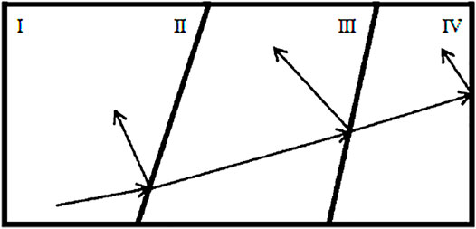
FIGURE 7. Schematic diagram of stress wave propagation in a three-layer structure.
Figure 8 shows the stress wave propagation inside the TC4-Al3Ti-Al laminated plate structure, when the bullet with a speed of 1100 m/s penetrates the target.
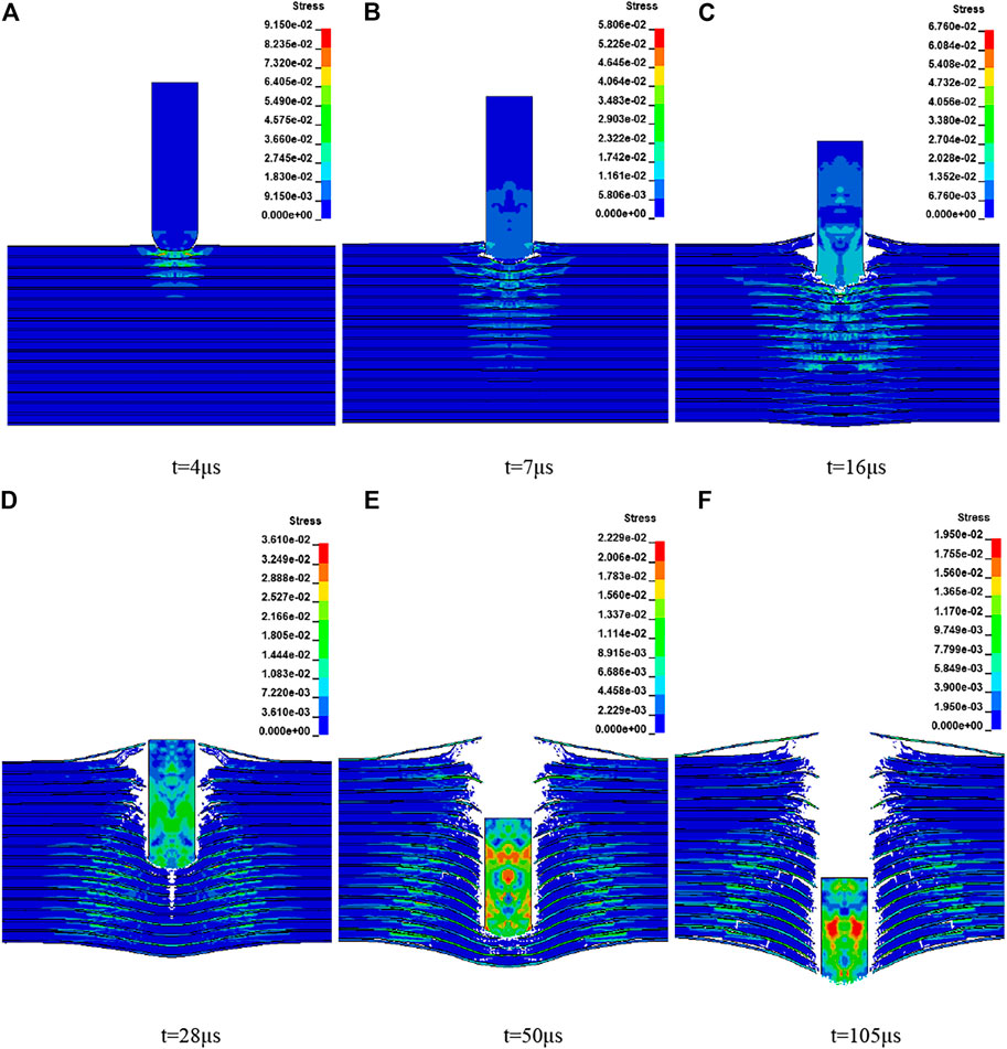
FIGURE 8. Stress nephogram of TC4-Al3Ti-Al targets under 1100 m/s bullet velocity. (A) t = 4 µs, (B) t = 7 µs, (C) t = 16 µs, (D) t = 28 µs, (E) t = 50 µs, (F) t = 105 μs.
When t = 4 µs, the projectile first impacts the surface of the plate target structure and forms stress waves inside the structure. The stress waves are reflected and transmitted continuously at the interlayer interface, which causes continuous bending of each layer material. The stress distribution inside the structure is roughly conical at the moment. The cone top position is about 1/3 of the structure, and the bottom width is about 2 times the diameter length of the projectile.
When t = 7 µs, the projectile completes the initial stage of penetration and cratering on the surface of the plate target. At this time, the stress inside the structure still presents a conical distribution, the conical top position is about 2/3 of the structure, and the bottom width is about 3 times the diameter length of the projectile. At this time, there are tensile waves reflected inside the projectile, and the wave front position is about 1/2 of the projectile.
Then the projectile stably penetrates the plate target, resulting in the fracture failure of each layer of the plate target. At the same time, as the stress wave reaches the free end on the back of the plate target, the stress wave is reflected as a tensile wave at the free end. Under the action of the tensile wave, cracks of varying degrees occur between layers that have not penetrated, which can be observed from Figure 8D,E. At the same time, it is found that the tensile stress in the structure is symmetrically distributed with the centerline of the projectile as the axis of symmetry. Finally, when T = 105 µs, the projectile penetrates the plate target.
According to the analysis of the interface propagation characteristics of the stress wave in the TC4-Al3Ti-Al targets, the stress wave produced a complex projection and reflection process at the TC4-/Al3Ti and Al3Ti/Al interface, which is basically the same as the three-layer material stress wave propagation diagram described in the literature (Miao, 2018), indicating that the stress distribution in the composite target is very complicated. Combining with the damage process of the composite target, it can be found that the stress distribution in the composite target has no effect on the composite target. The process has a significant impact.
Energy Conversion
Figure 9 shows the change in the total energy, kinetic energy, and internal energy of the projectile–target system with time, when the projectile had a velocity of 1,100 m/s. It is found that when there is the ballistic impact, the system’s kinetic energy decreases and the internal energy increases. More than 85% of the kinetic energy of the projectile is converted into the system’s internal energy. So, the increase in the internal energy of the system is the main form of the projectile’s kinetic energy dissipation. After the target plate is penetrated, the remaining kinetic energy of the system is mainly the kinetic energy of the projectile and the plug body, and the kinetic energy of some Al3Ti particles, which accounts for about 10% of the initial impact kinetic energy. At the initial stage of the penetration process, the total energy of the system slightly decreased mainly because of mass loss due to erosion of some units during impact.
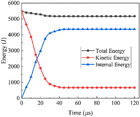
FIGURE 9. Projectile–target system energy vs time.
Conclusion
This study first optimized the arrangement order and layer thickness ratio of TC4-Al3Ti-Al laminated composites by the coupled finite-element genetic algorithm technique and then analyzed the anti-penetration performance of the optimized composites. The following conclusions can be drawn:
1) TC4-Al3Ti-Al laminated composites with a layer thickness ratio of 3:14:4 have the best anti-penetration performance.
2) The TC4 layer of TC4-Al3Ti-Al targets is a local tensile and shear failure, the Al layer is a petal-like tensile failure, and the Al3Ti layer is grinding and pulverization between particles.
3) The projectile kinetic energy is mainly converted into the internal energy of the TC4-Al3Ti-Al targets.
4) As the number of layers increases, the anti-penetration performance of TC4-Al3Ti-Al targets gradually increases. However, when the layer numbers are more than 30 layers, the increase in the layer numbers has little effect on the anti-penetration performance of the composites.
Data Availability Statement
The original contributions presented in the study are included in the article/Supplementary Material, further inquiries can be directed to the corresponding author.
Author Contributions
MY contributed to conceptualization; YL framed the methodology; HZ helped with validation; YL contributed to writing—original draft preparation; MY assissted with project administration and writing—review and editing; and HZ acquired funding. All authors have read and agreed to the published version of the manuscript.
Funding
This research was funded by the Foundation of Equipment Pre-Research Area (grant number 80923010401), the Natural Science Foundation for Young Scientists of Shanxi Province (grant number 201901D211203), and the Scientific Research Selected Foundation for Returned Scholars of Shanxi Province (grant numbers 20200022 and 20210040).
Conflict of Interest
The authors declare that the research was conducted in the absence of any commercial or financial relationships that could be construed as a potential conflict of interest.
Publisher’s Note
All claims expressed in this article are solely those of the authors and do not necessarily represent those of their affiliated organizations, or those of the publisher, the editors, and the reviewers. Any product that may be evaluated in this article, or claim that may be made by its manufacturer, is not guaranteed or endorsed by the publisher.
References
Abrate, S. (1994). Impact on Laminated Composites: Recent Advances. Appl. Mech. Rev. 47 (11), 517–544. doi:10.1115/1.3111065
Ahn, J.-H., Nguyen, K.-H., Park, Y.-B., Kweon, J.-H., and Choi, J.-H. (2010). A Numerical Study of the High-Velocity Impact Response of a Composite Laminate Using LS-DYNA. Int. J. Aeronaut. Space Sci. 11 (3), 221–226. doi:10.5139/IJASS.2010.11.3.221
Cao, H., Wang, Z., Xiao, Y., Han, Y., and Hou, T. (2018). Multi-level Optimization Design Method for Thick Composite Structures Considering Interlayer Stress. Adv. Aeronaut. Eng. 02, 199–208. doi:10.16615/j.cnki.1674-8190.2018.02.008
Cao, Y., Zhu, S., Guo, C., Vecchio, K. S., and Jiang, F. (2015). Numerical Investigation of the Ballistic Performance of Metal-Intermetallic Laminate Composites. Appl. Compos. Mater. 22 (4), 437–456. doi:10.1007/s10443-014-9416-1
Clemens, H., and Kestler, H. (2000). Processing and Applications of Intermetallic γ-TiAl-Based Alloys. Adv. Eng. Mater. 2 (9), 551–570. doi:10.1002/1527-2648(200009)2:9<551:aid-adem551>3.0.co;2-u
Johnson, G. R., and Cook, W. H. (1985). Fracture Characteristics of Three Metals Subjected to Various Strains, Strain Rates, Temperatures and Pressures. Eng. fracture Mech. 21 (1), 31–48. doi:10.1016/0013-7944(85)90052-9
Johnson, G. R., and Holmquist, T. J. (1994). “An Improved Computational Constitutive Model for Brittle Materials,” in AIP conference proceedings, Colorado Springs, Colorado, USA, June 28-July 02, 1993 (American Institute of Physics), 981–984. doi:10.1063/1.46199
Konieczny, M. (2013). Relations between Microstructure and Mechanical Properties in Laminated Ti-Intermetallic Composites Synthesized Using Ti and Al Foils. Kem 592-593, 728–731. doi:10.4028/www.scientific.net/kem.592-593.728
Launey, M. E., Munch, E., Alsem, D. H., Saiz, E., Tomsia, A. P., and Ritchie, R. O. (2010). A Novel Biomimetic Approach to the Design of High-Performance Ceramic-Metal Composites. J. R. Soc. Interf. 7 (46), 741–753. doi:10.1098/rsif.2009.0331
Miao, Y. (2018). Research on Al2O3/TC4/Kevlar Multilayer Lightweight Composite Armor and its Penetration Resistance. Master’s thesis. Nanjing(China): Nanjing University of Science and Technology.
Price, R. D. (2010). Effects of Ductile Phase Volume Fraction on the Mechanical Properties of Titanium-Aluminum Titanium alloy Metal-Intermetallic Laminate (MIL) Composites. Doctoral dissertation. San Diego(USA): University of California.
Vecchio, K. S. (2005). Synthetic Multifunctional Metallic-Intermetallic Laminate Composites. Jom 57 (3), 25–31. doi:10.1007/s11837-005-0229-4
Wilkins, M. L. (1978). Mechanics of Penetration and Perforation. Int. J. Eng. Sci. 16 (11), 793–807. doi:10.1016/0020-7225(78)90066-6
Xin, L., Yuan, M., Yao, Y., Yao, L., and Han, F. (2019). Numerical Study the Effects of Defects on the Anti-penetration Performance of Ti6Al4V-Al3Ti Laminated Composites. Mater. Res. Express 6 (8), 0865f8. doi:10.1088/2053-1591/ab2695
Yuan, M. N., Li, L., and Wang, Z. J. (2018). Study of the Microstructure Modulation and Phase Formation of Ti Al3Ti Laminated Composites. Vacuum 157, 481–486. doi:10.1016/j.vacuum.2018.09.002
Yuan, M., Wang, Z., Yao, Y., and Li, L. (2019). Finite Element Analysis of thermal Stresses in Ti-Al3Ti Metal-Intermetallic Laminated Composites. Results Phys. 15, 102706. doi:10.1016/j.rinp.2019.102706
Yuan, M., Yao, Y., Han, F., and Wang, Z. (2020). Evaluation of the Compressive and Anti-penetration Properties of Ti-Al3Ti-Al Laminated Composites. Adv. Composites Lett. 29, 2633366X2092187. doi:10.1177/2633366X20921874
Yuan, M., Yao, Y., Han, F., Xin, L., and Shen, X. (2020). Effects of Ductile Al on the Anti-penetration Performance of the Ti-Al3Ti Laminated Composites. Results Phys. 18, 103308. doi:10.1016/j.rinp.2020.103308
Keywords: genetic algorithm, anti-penetration properties, intermetallics, TC4-Al3Ti-Al laminated composites, structure optimization
Citation: Li Y, Zhang H and Yuan M (2022) Based on Genetic Algorithm to Analyze the Anti-Penetration Properties and Optimize the Structure of Ti-Al3Ti-Al Laminated Composites. Front. Mater. 9:806020. doi: 10.3389/fmats.2022.806020
Received: 31 October 2021; Accepted: 03 January 2022;
Published: 31 January 2022.
Edited by:
Xing Zhou, Xi’an University of Technology, ChinaReviewed by:
Bo Li, Case Western Reserve University, United StatesChang Yan, Xi’an University of Technology, China
Copyright © 2022 Li, Zhang and Yuan. This is an open-access article distributed under the terms of the Creative Commons Attribution License (CC BY). The use, distribution or reproduction in other forums is permitted, provided the original author(s) and the copyright owner(s) are credited and that the original publication in this journal is cited, in accordance with accepted academic practice. No use, distribution or reproduction is permitted which does not comply with these terms.
*Correspondence: Meini Yuan, bW55dWFuQG51Yy5lZHUuY24=