 Nina Graupner
 Jörg Müssig
- The Biological Materials Group, Department of Biomimetics, Faculty 5, HSB—City University of Applied Sciences, Bremen, Germany
In this study, the apparent interfacial and interlaminar shear strength (IFSS and ILSS) of single fibres and unidirectional (UD) viscose fibre-reinforced epoxy composites were characterised using different test methods. Microbond and pull-out tests were used to analyse the IFSS of single fibres embedded in epoxy and the transverse tensile test was applied to measure the IFSS of UD fibre-reinforced composites. The short beam shear test, single edge notched bending test (SENB), double-notched tensile test and double-notched compression test were applied to characterise the ILSS. The composites were produced from continuous tows with fibre mass fractions of 20%, 30% and 40% and fibres of different fineness (1.7, 3.3 and 28.0 dtex). The results showed that the different test procedures led to different trends of ILSS depending on the fibre mass fraction and fibre fineness used. The transverse tensile test revealed that the IFSS decreased with increasing fibre mass fraction and fibre diameter. A different trend was found with the short beam shear test and the SENB test for the ILSS. Here, higher values were detected with increasing fibre mass content, and the influence of the fineness was less noticeable. The double-notched shear tests (tensile and compression) showed a different trend: the ILSS increased with increasing fibre mass fraction from 20% to 30%. With a further increase to 40%, the ILSS tend to decrease slightly. An influence of the fibre fineness on the ILSS could not be statistically proven. The different trends of the test methods are attributed to the constitution of the composite and the different load application caused by the test procedures.
1 Introduction
To evaluate the quality of a composite material, the interaction between fibre and matrix plays an essential role (Gent and Liu, 1991; Piggott and Dai, 1991; Herrera-Franco and Drzal, 1992; Müssig and Graupner, 2020). Among other things, the mechanical properties can be influenced considerably. Good fibre/matrix adhesion results in a respectable load transfer from the matrix to the fibre. If the fibre/matrix adhesion is very strong, the strength and stiffness are usually positively influenced. However, depending on the material combination, toughness is reduced, especially in the case of tough fibres in a brittle matrix [e.g., regenerated cellulose fibres in a polylactide (PLA) matrix (Graupner et al., 2014)]. A strong adhesion prevents the energy-absorbing fibre pull-outs, which are responsible for a good energy dissipation. Weaker fibre/matrix adhesion, on the other hand, usually leads to increasing toughness, but the strength is reduced. If the adhesion is extremely poor, the strength and, the toughness, are negatively affected because almost no load transfer can take place from the matrix to the fibre (Müssig and Graupner, 2020).
A good fibre/matrix adhesion is essential for short fibre-reinforced plastics. In a previous study, it could be shown that surface treatment of regenerated cellulose fibres with lignin positively influences the fibre/matrix adhesion in both long fibre-reinforced PLA and short fibre-reinforced PLA. However, the improved fibre/matrix adhesion had a noteworthy effect on the short fibre-reinforced composite, which showed a significant increase in tensile strength. Improved fibre/matrix adhesion reduces the critical fibre length that must be present in a composite to achieve a reinforcing effect (Miwa and Horiba, 1994). Therefore, the influence of improved fibre/matrix adhesion on the properties of short fibre-reinforced composites with fibre lengths around the critical fibre length is generally higher (Graupner et al., 2014). That means the adjustment of the fibre/matrix adhesion can considerably influence the mechanical composite characteristics. For this reason, an analysis of the fibre/matrix adhesion is often mandatory. Various tests are available to determine the fibre/matrix adhesion. Individual elements (single fibres or individual fibre bundles from plants) can be embedded into the matrix and analysed concerning their apparent interfacial shear strength (IFSS). Composites can be tested for their apparent interfacial or interlaminar shear strength (ILSS) using different test methods (Gent and Liu, 1991; Piggott and Dai, 1991; Herrera-Franco and Drzal, 1992; Müssig and Graupner, 2020). The most common tests to determine the IFSS of single fibres or single fibre bundles are the fragmentation test, the microbond test, the pull-out test or the microindentation test. Composites are often analysed regarding their IFSS by using the the transverse tensile or bending test. The short beam shear test, the Iosipescu shear test or double-notched shear tests may be applied to determine the ILSS (Herrera-Franco and Drzal, 1992; Drzal and Madhukar, 1993; Olsson, 2011; Almeida et al., 2015; Müssig and Graupner, 2020).
Depending on the test method used, the results of the IFSS can differ significantly from single element tests (Müssig and Graupner, 2020), but also from composite tests to determine the IFSS or ILSS (Keusch et al., 1998; Almeida et al., 2015). However, even when using similar test methods, different studies often show different trends, e.g., depending on the fibre mass fraction or fibre fineness. For example, Woods and Ward (1994) found that the ILSS of a unidirectional high-modulus polyethylene fibre-reinforced epoxy resin, measured using a short-beam shear test, increases when the fibre has been plasma treated but decreases with increasing fibre content or fibre diameter. In contrast, Esnaola et al. (2016) observed no influence of fibre volume fraction on ILSS of glass fibre-reinforced polyester with fibre volume fractions between 40% and 60%, and Shanker Singh et al. (1991) determined for glass/epoxy composites an increase in ILSS with higher fibre content in the range between 32 and 57 vol.-% with a short beam shear test.
Nevertheless, by modifying the fibre surface to improve fibre/matrix adhesion, the same trend can often be observed with different test methods, which is frequently associated with increased characteristic values. However, the absolute values determined, often vary considerably. Drzal and Madhukar (1993), for example, investigated surface treatment and fibre finish of carbon fibres for epoxy composites. The authors used the single fibre fragmentation test, the microbond test, the micro indentation technique, a ±45° tension test, the Iosipescu shear test and the short beam shear test. The results of the untreated fibre-reinforced composites varied for the ILSS between 23.4 and 55.5 MPa from method to method. If the measured values of the composites with treated fibres are set in relation to values of untreated fibre composites, improvement factors between 1.3 and 2.1 were obtained (Drzal and Madhukar, 1993). Wang et al. (2019) also showed a similar trend for flax yarn modified with nanoclay for improved fibre/matrix adhesion with pull-out and short beam shear test results. The surface modification resulted in an increase of 18% for the ILSS measured with the short beam shear test and 71% for the IFSS measured with the pull-out test compared to untreated fibres (Wang et al., 2019). It can be concluded that a modification of the fibre/matrix interface can be detected with different methods, but the absolute values may differ significantly as well as the relationship between values of a modified and unmodified interface. In contrast to this, Teuber et al. (2013) showed that the results of a fibre pull-out test and a short beam shear test of untreated and enzyme-treated lyocell fibres are much more differentiated and provide significant differences in apparent ILSS for the fibre/matrix combinations (Teuber et al., 2013).
The previous discussion illustrates the problem regarding the comparison of results from different measuring methods (Pahr et al., 2002). However, even if the same measuring methods are used to analyse individual cellulose fibres or plant fibre bundles in different matrices or composites, considerable deviations in the measurement results are evident. Furthermore, the authors are not aware of any study comparing the results of off-axis tensile tests, short beam shear tests, SENB-tests and double-notched shear tests for cellulose fibre-reinforced plastics. Therefore, the influence of different methods for the analysis of fibre/matrix adhesion of regenerated cellulose fibre-reinforced epoxy will be investigated in this study. Regenerated cellulose fibre-reinforced composites are currently mainly used as tyre cord or as reinforcements in brake hoses (Einsiedel, 2017). Furthermore, there are applications in small series such as protective covers for smartphones or notebooks. Otherwise the authors are only aware of prototype applications such as the outer shell for a racing car developed by a team of students (formular student), a motorbike tank or a kayak (Graupner et al., 2022). Nevertheless, regenerated cellulose fibres have a high potential, in particular for applications that are subject to impact loads, due to their high tenacity (Bax and Müssig, 2008; Ganster et al., 2006). In contrast to natural fibres, regenerated cellulose fibres can be produced in a reproducible quality and are therefore particularly suitable for the intended comparison of methods for determining fibre/matrix adhesion. Thus, varying characteristic values due to a wide range of fibre properties can be excluded. The results of single fibre methods like microbond or pull-out tests and the before-mentioned composite tests will be compared. UD viscose fibre-reinforced composites with fibre mass contents of 20%, 30% and 40% and fibres of different fineness are produced for the different tests. Based on data available in the literature, it is expected that different test methods may lead to different results as a function of the fibre mass fraction or fibre fineness.
2 Materials and Methods
2.1 Fibre and Matrix
Danufil® KK viscose fibres were supplied with different fineness values of 1.7, 3.3 and 28.0 dtex by Kelheim Fibres GmbH (Kelheim, Germany) as continuous tows (135 ktex) with a bright/matt lustre. The equivalent diameter (theoretical diameter of a circular area corresponding to the cross-sectional area) of the fibres was calculated with the fibre density which was determined to be 1.521 ± 0.088 g/cm³ (Graupner et al., 2018), and the linear density of the different fineness values. An equivalent diameter of 11.9, 16.6 and 48.4 µm was calculated for Danufil 1.7, 3.3 and 28.0 dtex, respectively. Epikote RIMR 135 epoxy resin was used in combination with the hardener Epikure RIMH 137 as a matrix (Momentive Specialty Chemicals B.V., Rotterdam, Netherlands; mixing ratio 100:30; density 1.15 g/cm³).
2.2 Fibre Tensile Test
Before characterisation, fibres were conditioned according to DIN EN ISO 139 (Deutsches Institut für Normung, 2005). Fibre tensile characteristics were determined with a Fafegraph M testing machine (Textechno, Mönchengladbach, Germany) working with a pneumatic clamping system (PVC clamps). Eighty fibres of each fineness were investigated with a load cell of 100 cN at a gauge length of 20 mm and a strain rate of 50% (strain rate 10 mm/min).
2.3 Single Fibre Pull-Out Test and Microbond Test
The pull-out and microbond tests were performed on the coarsest fibres with a fineness of 28 dtex as handling of the very fine fibres is very difficult. It was not possible to realise such a small embedding length that allowed the fibre to be pulled out of the epoxy matrix. Silicone moulds were manufactured for the production of the pull-out samples from TFC Silikon Kautschuk (type 1 Abformsilikon weich 1:1 NV, Troll Factory RTV, Habekost Troll Factory Rainer Habekost e.K., Riede, Germany). For this purpose, Teflon® foils (PTFE-coated glass fibre fabric; thickness: 0.25 mm; Böhme Kunststofftechnik GmbH & Co. KG, Schwarzenbek, Germany) with the dimensions of about 8 cm2 × 8 cm2 were fixed upright in a rectangular mould, which was then filled with the silicone matrix to about 1 mm below the upper edge of the Teflon sheets. After curing, the Teflon® sheets were removed. The silicone mould was then slit on the long side, as shown in Figure 1A. The mould was unfolded, a fibre was inserted, and the cavity created by the Teflon foil was filled with epoxy resin. After curing of approx. 48 h at ambient conditions, the pull-out samples were demoulded (Figure 1B). The thickness of the polymer sheets of 18 valid specimens was, on average, 449 ± 229 µm.
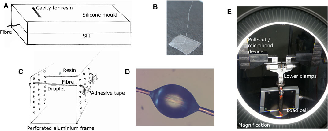
FIGURE 1. (A) Preparation set-up for pull-out test specimens and (B) prepared specimen, (C) preparation of microbond samples and (D) prepared microbond sample under a light microscope in polarised light, (E) testing device for pull-out and microbond tests (view through a magnifying glass).
For the microbond samples’ production, the fibres were placed over an aluminium frame made of perforated sheet metal and were fixed with adhesive tape. The epoxy resin was carefully dripped onto the fibre with a 0.9 mm glass cannula (Figure 1C). After curing, the samples were removed from the aluminium frame. The embedding length of 13 valid microbond samples was, on average, 335 ± 92 μm. A typical microbond specimen is shown in Figure 1D.
Before testing, the samples were conditioned according to DIN EN ISO 291 (Deutsches Institut für Normung, 2006). Pull-out and microbond specimens were tested on a self-manufactured testing device for a Zwick/Roell Z020 universal testing machine (Zwick/Roell GmbH, Ulm, Germany) equipped with a 5 N load cell (Figure 1E). The clamping length was 5 mm, and the test speed was set to 1 mm/min. The IFSS was evaluated by dividing the maximum pull-out force in N by the fibre’s embedded surface area in mm2.
2.4 Composite Production
Endless UD fibre-reinforced composites were produced from Danufil fibres with different fineness and fibre mass fractions of 20%, 30% and 40% in combination with the epoxy matrix. Fibre collectives were weighed with a scale (Kern 440–35 M, D = 0.01 g, Kern and Sohn GmbH, Balingen, Germany) for different specimen geometries [dog-bone shape tensile test specimen type 1 A according to DIN EN ISO 527-2 (Deutsches Institut für Normung, 1996), rectangular rods with the dimensions of 200 × 10 × 4 mm³, 200 × 10 × 3 mm³ and 200 × 15 × 4 mm³] and different fibre loads as described in (Graupner et al., 2018). The moulds were brushed with a mould release agent (Trennwachs, Standard 04.01A, Lange + Ritter GmbH, Gerlingen, Germany) prior using. The length of the sliver corresponds to twice the length of the specimen length. A nylon thread was attached to the middle of the 300 or 400 mm long sliver, which halved the sliver’s length and corresponded to the sample lengths of the composite material (150 mm for the production of tensile test specimens and 200 mm for the production of rectangular rods). The fibres were then impregnated in epoxy resin for at least 10 min, according to (Mader et al., 2012; Graupner et al., 2018). Then, the sliver was pulled through the mould with the nylon thread. The mould was closed, and the demoulding took place after 48 h curing at room temperature. The composites were tested at the earliest 2 weeks after manufacture.
2.5 Composite Tests
Before composite testing, samples were conditioned according to DIN EN ISO 291 (Deutsches Institut für Normung, 2006). All tests were carried out with a universal testing machine type Zwick Z 020 (Zwick/Roell GmbH, Ulm, Germany) working with a load cell of 20 kN. At least six specimens were tested per sample variety and test series.
2.5.1 Composite Tensile Test
Composites were tested for their tensile strength with the universal testing machine equipped with a pneumatic clamping system (clamping pressure: 1–2 bar). Test specimens type 1A were tested at a crosshead speed of 2 mm/min according to DIN EN ISO 527-2 (Deutsches Institut für Normung, 1996). The gauge length was set to 115 mm. The work at break in tension was determined with the load-displacement curves. Hull and Clyne (1996) state that “the work done in a tension or bending test is given by the area under a load–displacement plot and, provided this energy is all permanently absorbed in the specimen, the fracture energy is then found by simply dividing by the sectional area through which failure has occurred.” The load–displacement plot is given in N * m = 1 J or in our case in N * mm = 0.001 J.
2.5.2 Short Beam Shear Test
Short beam shear tests were carried out to determine the apparent interlaminar shear strength (ILSS) under mode II shear failure according to the standard DIN EN ISO 2377 (Deutsches Institut für Normung, 1989) for glass fibre-reinforced composites with a bearing distance of 15 mm and a testing speed of 1 mm/min. The radius of the pressure fin and the bearings was 5 mm and 2 mm, respectively. The specimens with dimensions of 20 × 10 × 3 mm³ were cut from the rectangular samples. The evaluation of test results was carried out according to the standard (Deutsches Institut für Normung, 1989).
2.5.3 Single Edge Notched Bending Test
SENB tests were carried out to determine the fracture toughness of the different composites. According to ASTM D 5045–99 (ASTM International, 1999) the fracture toughness is defined as the the critical-stress-intensity factor KIc which is a toughness property indicative of the resistance of a material to fracture. A pressure fin of 5 mm radius and bearings of a radius of 2 mm were used in combination with the universal testing machine Z 020. The span length (L) was set to 20 mm, and the testing speed to 1 mm/min. Test specimens were produced from rectangular samples with a length of 25 mm, a width (W) of 10 mm, a thickness (T) of 4 mm and a notch depth (a) of around 4.5 mm. Results were evaluated as described, e.g., in (Kobayashi and Kitagawa, 2016; Pickering et al., 2011). The critical load was defined as the onset of non-linear behaviour in the curve (see Figure 2, corrected curve, continuous line). The condition “2B < W < 4B” as specified in the standard ASTM D 5045–99 (ASTM International, 1999) is fulfilled, but the span length is lower, which may significantly affect the results. Therefore, the calculated KIc factors were normalised by showing the highest value as 100%, as in this case, it is only a matter of comparing the different composites within a test series.
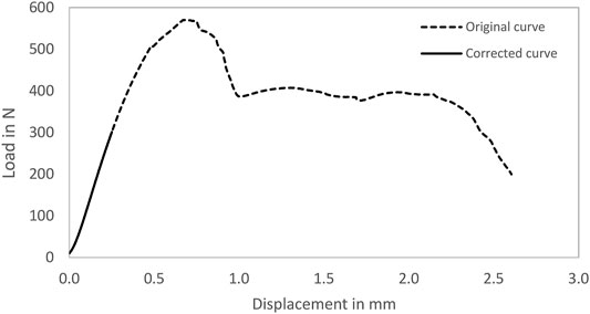
FIGURE 2. Exemplary original (dotted line) and corrected load-displacement curve (continuous line; onset of non-linear behaviour) of a SENB test specimen (30% Danufil 3.3 dtex/epoxy).
The apparent ILSS (mode II) from SENB tests was calculated according to Bader and Ellis (1974) with Eq. 1. σc is the critical stress from the SENB test in MPa, W the specimen width in mm, a the notch depth in mm and L the span length in mm.
2.5.4 Double-Notched Compression Test
Double-notched compression tests were carried out to determine the apparent ILSS (mode II) in compression of the composites. Test specimens were prepared from the rectangular samples measuring 25 × 10 × 4 mm³ according to the ceramic standard (Deutsches Institut für Normung, 2003). Two opposing notches with a depth of 2 mm and a width of 0.8 mm were inserted at a distance of 10 mm. The load was applied with a testing speed of 2 mm/min and was related to the shear area for the calculation of the apparent ILSS. The test was terminated with compression of max. 50%. Following the initiation of the shear failure and the force drop, a new force increase occurred after the notch width was reduced to 0 mm by the pressure load (compare Figure 3). Therefore, the force values before the first force drop were used. This force value in N was related to the shear area in mm2 to calculate the apparent ILSS.
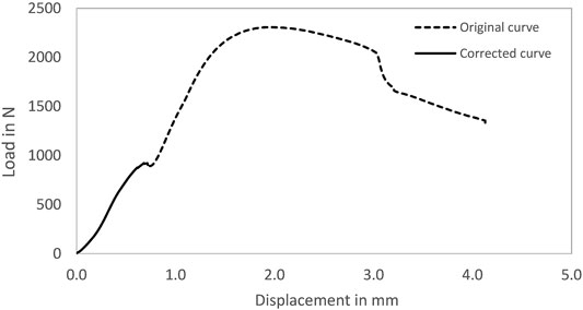
FIGURE 3. Exemplary original (dotted line) and corrected load–displacement curve (continuous line; first force drop) of a double-notched compression test specimen (30% Danufil 3.3 dtex/epoxy).
2.5.5 Double-Notched Tensile Test
According to DIN EN ISO 65148 (Deutsches Institut für Normung, 1989), double-notched tensile tests were used to determine the apparent shear failure in tension (ILSS, mode II). Specimen dimensions of 60 × 15 × 4 mm³ (deviation from the standard) were produced from the rectangular samples. Two opposing notches with a depth of 2.2 mm and a width of 0.8 mm were inserted at a distance of around 12.5 mm. To prevent the specimens from buckling at the notches, two rectangular steel plates with the same specimen width and a thickness of 4 mm were also clamped. The steel plates were clamped in opposite directions, so that one steel plate spanned one notch on each side and thus prevents buckling. Tensile tests with the universal testing machine (pneumatic clamping system; clamping pressure: 1–2 bar) were carried out at a gauge length of 40 mm and a testing speed of 2 mm/min. The maximum force in N was related to the shear area in mm2 to calculate the apparent ILSS.
2.5.6 Transverse Tensile Test
Small test specimens with a fibre orientation perpendicular to the test direction were produced from the rectangular samples with dimensions of 15 × 10 × 4 mm³. The universal test machine Z 020 operating with a 2 mm/min crosshead speed was used with the pneumatic clamping system (clamping pressure: 1–2 bar). The gauge length was set to 5 mm. The maximum force in N was related to the cross-sectional area in mm2. This transverse tensile strength is considered as the apparent IFSS.
2.6 Scanning Electron Microscopy
Fracture planes from tensile and double-notched tensile test specimens were examined with scanning electron microscopy (SEM type JSM 6510, Jeol, Eching, Germany) operating with emission electrons. Before SEM investigations, the samples were sputtered with gold for 60 s under a current of 56 mA with a Bal-Tec sputter coater type SCD 005 (Bal-Tec, Liechtenstein).
2.7 Statistics
The statistical evaluation of test results was carried out with the open-source software R version 3.5.1 (http://www.r-project.org/). Results were investigated regarding a normal distribution with a Shapiro test. To prove whether there are significant differences between the data of variable samples, for normally distributed data with homogenous variances the Tukey-test and for data which are not distributed normally the Wilcoxon test was chosen. All tests were performed with a level of significance α = 0.05. Results are shown as Box-Whisker-plots with the mean values as rhombuses. Significant differences are designated with different letters, and an asterisk identifies results which are not distributed normally.
3 Results and Discussion
3.1 Fibre and Composite Characteristics
The fibres used, differ in their fineness and fibre cross-sectional area. Due to the influence of size effects and the higher probability of defects with a larger cross-sectional area, the fibres’ tensile strength decreases, as shown in Figure 4 and discussed in an earlier study (Graupner et al., 2018).
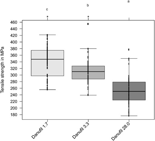
FIGURE 4. Tensile strength of Danufil viscose fibres having a fineness of 1.7, 3.3 and 28.0 dtex. Results are shown as Box-Whisker Plots. Different letters indicate significant differences, a * marks results which do not follow a normal distribution.
The same slight trend is also visible for the composites (compare Figure 5): the coarser fibres lead to a lower tensile strength. Compared to the neat matrix, all fibre types have been able to achieve a significant reinforcing effect. Composites with a higher fibre mass fraction show a significantly higher tensile strength than composites with lower fibre content. From a statistical point of view, no significant differences could be found for composites produced from Danufil 1.7 dtex and 3.3 dtex, despite the higher tensile strength of Danufil 1.7 dtex.
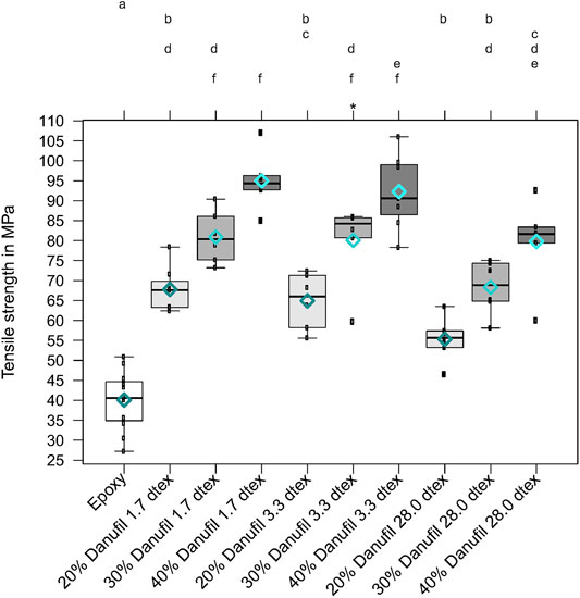
FIGURE 5. Tensile strength of Danufil fibre-reinforced composites. Results are shown as Box-Whisker‐Plots with the mean values as rhombuses. Different letters indicate significant differences, a * marks results that do not follow a normal distribution.
As shown in Figure 6, the fracture surfaces of the composites show clear differences. Composites reinforced with finer fibres show a relatively brittle fracture behaviour with a fibre mass fraction of 20%. The matrix is broken smoothly, and the fibres have barely been pulled out of the matrix. With fibre mass proportions of 30% and 40%, the fracture surfaces become more fissured. In some cases, entire fibre collectives were pulled out. It is also evident that composites reinforced with Danufil 1.7 dtex have a higher number of voids in the fracture surface. The determination of density and void volume could confirm this observation. Table 1 shows a higher void volume for composites reinforced with Danufil 1.7 dtex fibres than composites with Danufil 3.3 dtex. The coarse 28 dtex fibres, on the other hand, tend to have the lowest porosity. The higher void volume of composites reinforced with the fine fibres may have been caused by the larger specific fibre surface, making it more difficult for the matrix to penetrate and wet the fibres. It is assumed that the higher strength of the Danufil 1.7 dtex fibres compared to the 3.3 dtex fibres compensates for this, and comparable strength of the composites is the result. Ashir et al. (2019) showed that the influence of voids on the reduction in tensile strength of carbon fibre-reinforced epoxy is particularly pronounced when the percentage of voids increases from 0 to about 2.5%. If the void volume increases up to approx. 6.3%, the influence is significantly lower but still present. For composites with the coarse 28 dtex fibres, it can be seen that the fibres were pulled out of the matrix. Compared to the fine fibres, the lower specific fibre surface is assumed to be the reason for a lower apparent adhesion between fibre and matrix, resulting in fibre pull-outs.
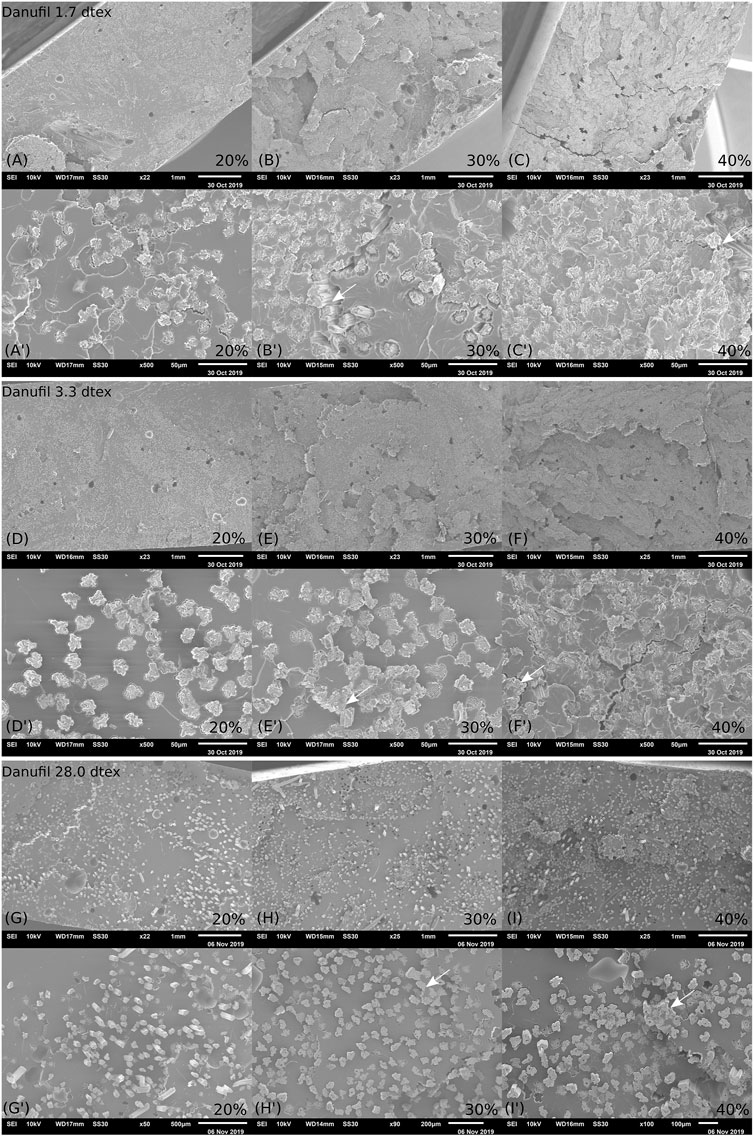
FIGURE 6. SEM micrographs of composites reinforced with different fine Danufil fibres and fibre mass fractions: (A–C) Danufil 1.7 dtex, (D–F) Danufil 3.3 dtex, (G–I) Danufil 28.0 dtex). A few places where whole fibre collectives were pulled out are marked with an arrow.
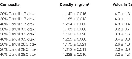
TABLE 1. Density and voids of the different Danufil fibre-reinforced composites (mean values ± SD).
The work at break determined as area under the force-displacement curves obtained from the tensile tests and the normalised data of the fracture toughness from the SENB tests are shown in Figure 7. Both methods show the same trend: higher fibre mass proportion leads to an increased work at break and fracture toughness. Besides, a slight trend can be seen that both values decrease when using coarser fibres with a lower tensile strength. From a statistical point of view, the composites reinforced with Danufil 1.7 dtex and 3.3 dtex do not differ significantly, and therefore, a comparable work at break and fracture toughness can be assumed. Merely the composite made of Danufil 28 dtex shows significantly lower values. The increased work at break and fracture toughness with increasing fibre content can be explained by the significantly higher elongation at break of the fibres (>16%) compared to the matrix (1.4%). Although the finer fibres (1.7 dtex and 3.3 dtex) have a significantly lower elongation at break of 16.7% and 22.6%, the composites with the 28 dtex fibres show lower work at break and normalised fracture toughness values despite an elongation at break of the fibres of 34.4%. This means that this significantly increased elongation of the coarse Danufil fibres cannot be transferred to the composite. The elongation of composites reinforced with the different fine fibres and a fibre mass fraction of 30% ranged between 1.8% and 2.4%. Due to the smaller specific fibre surface of the coarse fibres, less energy is absorbed by fibre pull-outs during breakage. Because of the significantly higher elongation of the fibres compared to the matrix, the full reinforcement effect of the fibres in the composite cannot be utilised, as described in a previous study (Graupner et al., 2019).
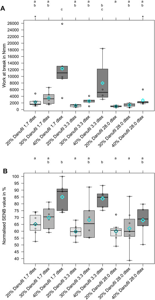
FIGURE 7. Work at break determined from force-displacement curves of tensile tests (A) and SENB value normalised to the highest value obtained by a single edge notched bending test. (B) Results are shown as Box-Whisker‐Plots with the mean values as rhombuses. Different letters indicate significant differences. A * marks results which do not follow a normal distribution.
3.2 Interfacial Shear Strength From Single Fibre Pull-Out and Microbond Methods
The results of the apparent IFSS determined with single fibre methods (pull-out test and microbond test) do not differ significantly (see Figure 8). Yang and Thomason (2010) also found a good correlation between the results of IFSS of individual glass fibres in a polypropylene (PP) matrix determined with pull-out and microbond tests. In a previous review, we were able to show that IFSS values depend very much on the preparation method, the execution of the tests and the evaluation of the results. A direct comparison of results is only possible if the same methodology is used (Müssig and Graupner, 2020). In this case, the pull-out and microbond specimens were prepared similarly apart from the specimen geometry. The main difference between the tests performed is that one end of the fibre was cut off from the pull-out specimen at the level of the matrix, whereas the fibre end was left in place at the microbond specimens. This allows the friction between fibre and matrix to be measured over a more extended period. Nevertheless, comparable results could be achieved with both methods for the IFSS.
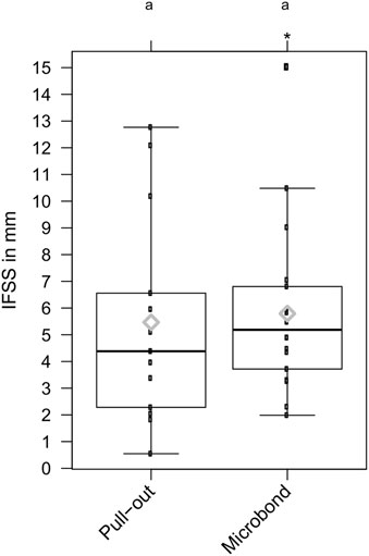
FIGURE 8. Interfacial shear strength (IFSS) of Danufil 28 dtex fibres embedded in an epoxy matrix determined by pull-out and microbond tests. Results are shown as Box-Whisker‐Plots with the mean values as rhombuses. No significant differences were found. A * marks results which do not follow a normal distribution.
3.3 Interfacial Shear Strength From Transverse Tensile Tests
The transverse tensile strength, which is often used as an indicator for the apparent IFSS (Jang, 1992), shows an opposite trend (Figure 9) to the longitudinal tensile strength (compare Figures 5): an increase in the fibre mass fraction leads to a decrease in the transverse tensile strength or IFSS, respectively (Figure 9). The composites reinforced with Danufil 3.3 dtex show a slightly higher IFSS but do not differ statistically from the composites’ results made of Danufil 1.7 dtex. As discussed for the longitudinal tensile strength, the higher void ratio of the finer 1.7 dtex fibre-reinforced composites compared to the 3.3 dtex fibre-reinforced composites can be the reason for the slightly lower characteristic values since defects such as voids have a stronger influence on the properties measured in the transverse direction to the fibre orientation (Madhukar and Drzal, 1991). Dong (2016) has found that the critical void content for carbon fibre-reinforced composites is around 2%. For void contents above this critical value, transverse strength decreases with increasing void content, and the strength reduction decreases with increasing fibre volume fraction. It has been shown that voids have minor effects on the longitudinal tensile strength of UD endless fibre-reinforced composites (Madhukar and Drzal, 1991; Dong, 2016), whereby a certain influence is still present (Ashir et al., 2019). As shown in Table 1, the void content in the composites decreases as a function of fibre fineness from fine to coarse. Therefore, it can be concluded that the lower IFSS of the composites with Danufil 28 dtex is mainly due to the lower specific surface area.
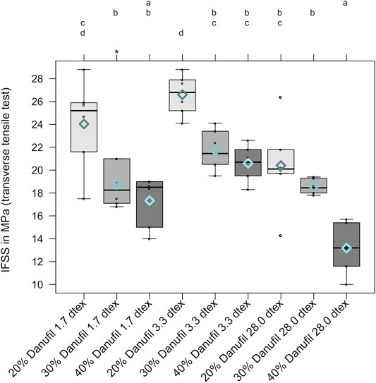
FIGURE 9. Interfacial shear strength (IFSS) determined by a transverse tensile test. Results are shown as Box-Whisker-Plots with the mean values as rhombuses. Different letters indicate significant differences. A * marks results which do not follow a normal distribution.
The matrix properties dominate the transverse tensile strength. With a non-optimal fibre/matrix adhesion, the fibres tend to act as defects, so the transverse tensile strength of fibre composites is often lower than that of the pure matrix (Bunsell and Renard, 2005). The same trend was demonstrated in a study by Le Duigou et al. (2014). Flax fibre-reinforced polylactide (PLA) with 20%, 30%, and 40% fibre mass fraction showed a significantly lower transverse tensile strength than the pure matrix and a significant reduction with increasing fibre mass fraction (Le Duigou et al., 2014). Additionally, voids in the interface promote early failure. Due to the significantly lower specific fibre surface of the coarse fibres, a smaller bonding surface of the fibre is available for the matrix leading to lower transverse tensile strength. In the overall consideration, the transverse tensile test was found to be one of the more sensitive techniques to assess the IFSS in composites [(Fitzer and Weiss, 1987) cited in (Jang, 1992)].
3.4 Interlaminar Shear Strength From Bending Methods
In contrast to the transverse tensile test, the results from the bending methods (short beam shear test and SENB test) rather represent the trend of the longitudinal tensile tests. As the proportion of fibre mass increases, the composites’ apparent ILSS values increased clearly (see Figure 10). However, from a statistical point of view, no influence of fibre fineness on the ILSS can be determined, leading to the assumption that these methods are less sensitive to fibre fineness, and the different tensile strength of the fibres has a minor influence. However, the ILSS values of the short beam shear test and SENB test are of a similar order of magnitude. It is assumed that the different trends in the transverse tensile test and the bending test results are based on the different type of load. While the fibres in the transverse tensile test tend to act as defects, they may act as reinforcement under bending loads due to the longitudinal fibre orientation. However, it is assumed that the reason is mainly to be found in the constitution of the composites. For glass and carbon fibre-reinforced laminates, the functionality of the short beam shear test could be proven (Cui et al., 1994; Hoecker et al., 1995; Keusch et al., 1998; Davies et al., 2005; Selmy et al., 2012; Almeida et al., 2015; Esnaola et al., 2016) and the influence of voids on the apparent ILSS could also be demonstrated (Zhan-Sheng Guo et al., 2009) as well as the influence of fibre orientation (Almeida et al., 2015). Nevertheless, it should also be noted that the short beam shear test also displays problems such as complex stress states in the specimen, compressive stresses present underneath the load applicator and the strong dependence of the results on the failure modes, flexural stresses increasing towards the top and bottom surface and the span to specimen thickness ratio (Feraboli et al., 2004; Olsson, 2011).
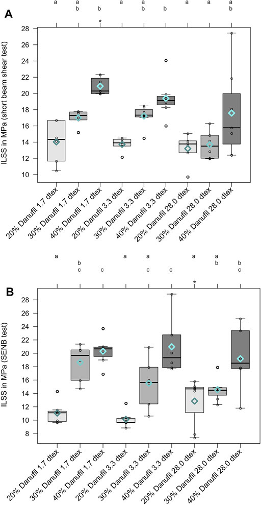
FIGURE 10. Interlaminar shear strength (ILSS) determined by a short beam shear test (A) and ILSS determined by a SENB test (B). Results are shown as Box-Whisker-Plots with mean values as rhombuses. Different letters indicate significant differences. A * marks results which do not follow a normal distribution.
It must be taken into account that the samples examined are not multi-layer composite laminates; they can be considered as single layers with individually distributed fibres (compare Figure 6). It cannot be excluded that other failure modes than pure shear failure led to the failure of the test specimens. It is presumed that the specimens also failed to a certain extent due to tensile and compressive stresses. In this case, it is suspected that the flexural rather than the shear strength was measured. Compston and Jar (1999) showed for glass fibre-reinforced vinylester that cracks in laminates are initiated in the matrix-rich layer between individual fabric layers. Since there are no matrix-rich layers in our composites, crack branching is assumed to occur rather than pure in-plane shear failure. Ahmed and Vijayarangan (2008) state that interlaminar shear failure may not also take place at the laminate midplane. It is challenging to ensure pure shear failure along with the interface, which makes it difficult to interpret the short-beam shear test data.
It seems that the influence of voids plays a minor role in the investigated composites. In our case, it could be shown that the proportion of voids, which harms the apparent adhesion between fibre and matrix, does not increase significantly with increasing fibre mass (see Table 1). Nevertheless, the composites with the finest 1.7 dtex fibres showed a higher void ratio. Therefore, the transverse tensile strength of composites with Danufil 1.7 dtex is comparable to composites reinforced with Danufil 3.3 dtex. In contrast, these materials tended to show the highest ILSS values from the short beam shear test, and an influence of fibre fineness with decreasing ILSS was generally obvious when using coarser fibres. This indicates that the material properties in the short beam shear test are more fibre-dominated than defect-dominated. Ashir et al. (2019) confirm for carbon fibre-reinforced epoxy that the influence of voids on the bending properties is less pronounced than on the tensile properties. However for multilayer composite laminates, a clear influence of the voids on the ILSS could be proven with a short beam shear test. The ILSS decreases with an increased proportion of voids. The reason for this phenomenon is the reduction of the sliding resistance between individual fibre layers by increasing void content (Ashir et al., 2019). In the overall consideration, it seems that the short beam shear test is less sensitive to voids compared to the transverse tensile test and the properties of the reinforcing fibres are more apparent. The ILSS from the SENB test, on the other hand, shows no sensitivity to fibre fineness. However, both methods show an opposite trend to the results from the transverse tensile test.
For comparing our results with data from the literature, some trends from other studies are listed here. Roe and Ansell (1985) also show an increase in ILSS between fibre volume fractions of 10% and 60% for jute fibre-reinforced unsaturated polyester (UP) with a simultaneous increase in tensile strength and Young’s modulus. A similar trend was observed by Lee et al. (2009) for a lyocell fabric-reinforced PBS matrix. The authors found an increasing ILSS up to a fibre mass fraction of 50% and a decrease at a fibre content of 60%. Arulmurugan and Narayananan (2019) showed, in contrast, for jute fibre-reinforced UP that the ILSS measured with a short beam shear test increases with increasing jute fibre content from 5% to 25%. With a further increasing fibre mass fraction up to 30%, the ILSS decreased. The authors reported the same trend for the flexural strength, but the tensile strength decreased significantly from a fibre mass fraction of 20%. It can be concluded that the tensile characteristics are much more sensitive against a weaker fibre/matrix adhesion than the bending properties. A study by Malaba and Wang (2015) displays a reverse trend for a viscose fibre-reinforced furan resin. A reduction of ILSS was shown with an increasing fibre mass fraction from 51% to 75%. However, these fibre mass fractions are significantly higher than those used in the present study and the authors simultaneously determined a reduction in flexural strength with an increasing fibre mass fraction. They observed by microscopy a decreasing fibre/matrix adhesion with increasing fibre content. Another controversial trend was reported by Wood and Ward (1994). The ILSS of a unidirectional high-modulus polyethylene fibre-reinforced epoxy, measured using a short-beam shear test, decreases with increasing fibre content. The authors concluded that the shear failure is controlled by the adhesion between fibre and matrix for fibre volume fractions above 30%. At a fibre volume below 30%, the failure is increasingly dominated by the shear failure of the resin. However, analogous to our study, the authors observed a reduction in ILSS with increasing fibre diameter.
3.5 interlaminar Shear Strength From Double-Notched Tensile and Compression Tests
Another trend compared to the before-mentioned results was determined by double-notched tensile and compression tests. Double-notched shear tests were developed for materials that do not yield acceptable data, e.g., with the short beam shear test (Almeida et al., 2015) and display a more uniform state of interlaminar shear stress in the gauge area (Shokrieh and Lessard, 1998; Lijun et al., 2008). However, there are also criticisms that the shear stress is not uniformly distributed in the gauge section (Olsson, 2011). A stress concentration occurs close to the notches initiating the shear failure (Weidenmann et al., 2015). It should be noted that the shear stress distribution becomes more uniform for increased material anisotropy and small notch-distance to thickness ratios of the specimens. The notch size and the distance from the notches to the specimen’s loaded ends seem not to influence the stress distribution significantly (Dadras and McDowell, 1990). The SEM micrograph in Figure 11 shows an example of a fracture surface after a double-notched tensile test of a 40% Danufil 3.3 dtex-reinforced epoxy composite. Shear failure is clearly visible. The sample fractured parallel to the fibres. Particles of matrix residues can be seen on the surface of the fracture plane.
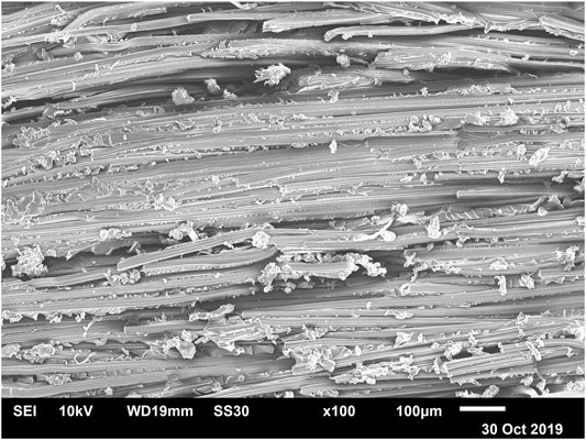
FIGURE 11. SEM micrograph of a fracture surface of a 40% Danufil 3.3 dtex reinforced epoxy after the double-notched tensile test.
When comparing the results from the double-notched tensile test (Figure 12A) and the compression test (Figure 12B), it becomes clear that the absolute IFSS values differ significantly, but the trend is the same. The highest ILSS was measured in trend with a fibre mass fraction of 30%. An influence of fibre fineness cannot be proven from a statistical point of view. Even if the composites with the coarse Danufil 28 dtex fibres show slightly lower values overall, the difference to the composites with the finer fibres is not significant.
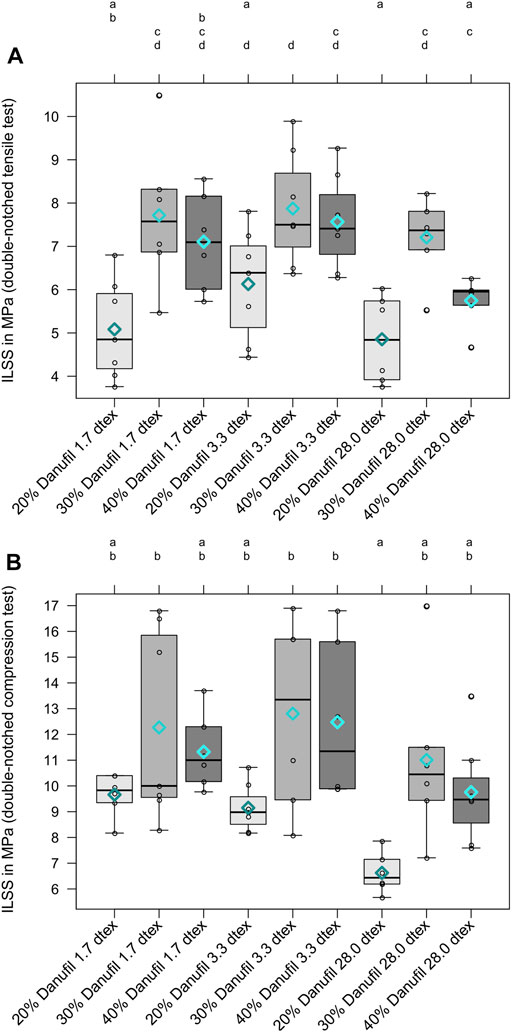
FIGURE 12. Interlaminar shear strength (ILSS) determined by a double-notched tensile test (A) and ILSS determined by a double-notched compression test (B). Results are shown as Box-Whisker-Plots with the mean values as rhombuses. Different letters indicate significant differences.
Under tensile and compressive loading of the double-notched test specimens along with the fibre orientation, it is assumed that shear failure occurs mainly at the matrix level in the specimens with low fibre content (20%). Wood and Ward (1994) have shown that shear failure is controlled by the adhesion between fibre and matrix for fibre volume fractions above 30%. However, at a fibre volume below 30%, the failure is increasingly dominated by the resin’s shear failure. It is assumed that this phenomenon also occurs in double-notched tension and compression tests. By loading along the longitudinal axis of fibre orientation, the fibres act less as defects compared to a transverse tensile test. However, by increasing the fibre mass fraction to 30%, higher ILSS is achieved. Even if the fibres are cut in the plane by the notches, the critical fibre length is exceeded due to the large spacing of the notches. Under shear load, the fibre/matrix adhesion seems to be sufficiently good to transfer stress from the matrix to the fibre. However, by further increasing the fibre mass fraction to 40%, no further increase in ILSS could be found; the characteristic values tend to be slightly lower. It is assumed that fibre-fibre interactions also play a role (Almeida et al., 2013). The shear forces can still be transferred to the fibres, but shear failure also occurs between individual fibres. It is assumed that the ILSS would be further reduced if the proportion of fibre mass continued to increase. This aspect should be investigated in future research work.
3.6 Comparison of Different Methods
In the present study, a total of seven methods for measuring fibre/matrix adhesion of regenerated cellulose fibre-reinforced epoxy were investigated. Both single fibre methods, pull-out and microbond test provided comparable apparent IFSS values due to similar parameters during sample preparation, testing and evaluation. However, single fibre methods are often limited. For the tests, a sufficiently small embedding length below the critical fibre length must be realised. The preparation of pull-out and microbond samples when using very fine fibres and fibres with low strength is challenging and, in some cases, hardly possible. Single fibre methods are often accused of not reflecting the load case in a composite material (Beckert and Lauke, 1997). Effects, such as differently shaped fibre ends, interconnected fibres, and their interaction in the entire composite (Fan and Hsu, 1989) cannot be reproduced with single fibre methods. Besides, inhomogeneities of the fibre surface or small voids lead to different stress distributions along the interface, especially at the fibre ends, where stress concentrations already exist. The shorter the embedding length in the pull-out or microbond specimen, the higher the influence of the stress concentrations. It is almost impossible to reproduce the same stress state in different samples (Beckert and Lauke, 1997).
In contrast to single fibre methods, the methods for measuring the apparent IFSS and ILSS of UD composites (transverse tensile test, short beam shear test, double-notched tensile test and double-notched compression test) showed completely different trends in the results as a function of fibre load and fibre fineness (see Figure 13). According to the current state of knowledge, we assume that the different trends are due to the different test procedures and loading cases, as all samples were manufactured under exactly the same conditions.
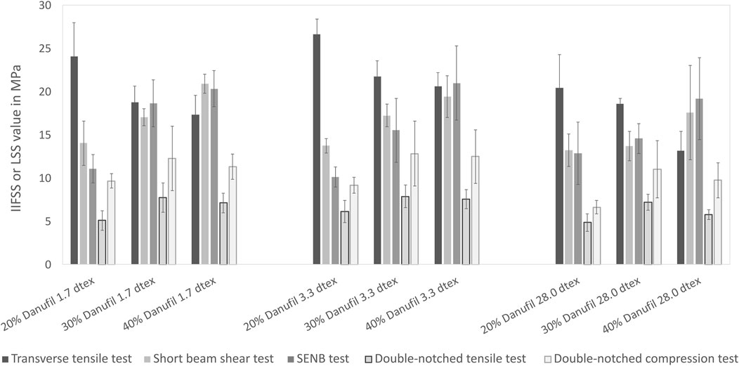
FIGURE 13. Comparison of apparent IFSS data from transverse tensile and ILSS data obtained by short beam shear, SENB, double-notched tensile and double-notched compression tests. Results are shown as mean values with standard deviations as error bars.
Table 2 provides an overview of published data on regenerated cellulose fibre-reinforced plastics that were examined with regard to their IFSS and ILSS. It can be seen that the characteristic values of different materials with the same fibre content, which were examined with the short beam shear test, differ significantly due to the mentioned reasons.
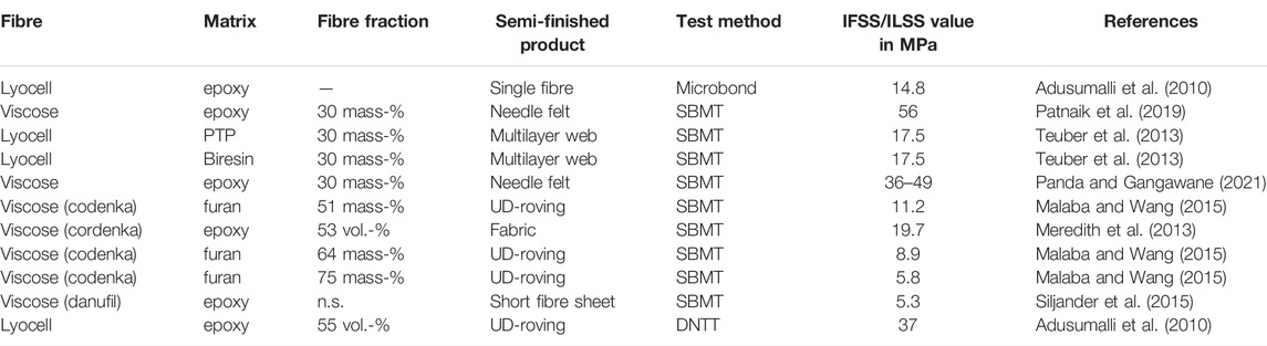
TABLE 2. IFSS and ILSS values of regenerated cellulose fibre-reinforced thermosetting matrices presented in literature (IFSS measured by microbond-tests, ILSS measured by short beam shear tests–SBMT or double-notched tensile tests–DNTT).
The transverse tensile test showed a clear trend of decreasing IFSS with increasing fibre mass. The test appears to be sensitive to the influence of fibre fineness and the proportion of voids in the composite. Despite the lower specific fibre surface of Danufil 3.3 dtex fibres, a slightly higher IFSS was measured compared to Danufil 1.7 dtex-reinforced composites. It is assumed that the higher void content of Danufil 1.7 dtex-reinforced composites led to this result, as the tensile properties of a composite transverse to the fibre orientation are strongly influenced by the presence of voids (Dong, 2016). The IFSS of composites reinforced with Danufil 28 dtex was significantly lower due to the lower specific fibre surface available for the fibre/matrix bond. Overall it has been shown that the transverse tensile test is one of the more sensitive techniques for assessing the apparent IFSS in composites [(Fitzer and Weiss, 1987) cited in (Jang, 1992)]. It is assumed that the influence of fibre fineness can be demonstrated for the same void content of different composite materials.
The determination of ILSS from bending methods (short beam shear test and SENB test) shows a reverse trend to the transverse tensile test results. With increasing fibre content, the ILSS increases with both methods. In the short beam shear test, a slight influence of the fibre fineness with decreasing ILSS can be seen using coarser fibres. This trend is not visible in the SENB test results. Although the bending properties are less affected by an increasing void content than the tensile properties, the reinforcing effect of the finer fibres is more pronounced, and the voids may harm the ILSS (Ashir et al., 2019). Since the materials used are not laminates, it cannot be completely excluded that the specimens only failed under shear stress. Failure could also have occurred under tensile and bending loads, which is why the short beam shear test is not to be preferred for this kind of materials used. Compared with single fibre methods the ILSS values are clearly higher. A similar trend was confirmed by Adusumalli et al. (2010) who determined a 50% higher ILSS value by the short beam shear test for lyocell/PP than their respective IFSS values measured with a microbond test.
A third trend was determined by the double-notched tensile and compression test: the apparent ILSS increased from a fibre mass fraction of 20%–30% and was then slightly reduced at a fibre mass fraction of 40%. No significant differences were found between composites reinforced with Danufil 1.7 dtex and 3.3 dtex. There was a tendency to show a slightly lower ILSS for composites reinforced with Danufil 28 dtex. The hypothesis is formulated that composites’ shear failure with a fibre mass fraction of 20% takes place predominantly at the matrix level. At a fibre mass fraction of 40%, fibre-fibre interactions could cause the ILSS to drop slightly. In addition to this, the proportion of voids in all composites investigated is rather higher with 40% fibres. In the case of shear failure, it is assumed that voids’ have a considerable impact on the failure of double-notched specimens. However, these hypotheses should be verified in future research work.
It can be summarised that fibre fineness, fibre mass fraction and void content have different influences on the results of different IFSS and ILSS measuring methods (Figure 13). The magnitude of the characteristic values also varies. The structure and composition of the composite material seem to have a significant influence on the results. For the materials investigated here, the transverse tensile test seems to provide the best information as the influence of fibre fineness, fibre mass fraction and voids can be represented. However, it should be noted that the use of other material pairings, e.g., based on thermoplastic matrices or fibres with significantly different mechanical properties and different fibre/matrix adhesion could lead to different trends.
4 Conclusion
This study investigated the influence of fibre fineness and fibre mass content on mechanical properties and fibre/matrix adhesion of viscose fibre-reinforced epoxy composites. The tensile strength of the fibres showed lower characteristic values for fibres with increasing fibre diameters due to the higher probability of defects. This trend was found to a certain extent in the composites, where an increased fibre mass proportion leads to a significant increase in tensile strength. Due to the high ductility of viscose fibres, the work at break determined with tensile tests and the normalised fracture toughness measured with SENB tests also increased compared to the pure matrix with increasing fibre mass fraction and fibre fineness. The results also showed that the wetting of the finer fibres with the matrix is more complicated so that the void volume tends to increase with the use of finer fibres. The voids had different effects on the five test methods investigated to determine the IFSS or ILSS. In contrast to the comparable results obtained with the pull-out and microbond test to determine the apparent IFSS, no consistent trends and results could be achieved with the five different tests as a function of fibre fineness and fibre mass fraction. While the transverse tensile test was found to be sensitive to detect the influence of fibre fineness, fibre mass fraction and the presence of voids, the short beam shear test and the SENB test seem to be less suitable for the investigated materials, as they are not available as laminates and no clear shear failure in the neutral plane can be guaranteed. In contrast, the loading of double-notched test specimens under tensile and compressive loading showed that shear failure is more initiated in the matrix at a fibre mass fraction of 20%. The highest ILSS was measured at a fibre mass fraction of 30%, which slightly decreased at a higher fibre mass fraction of 40%. Depending on the material used, it is necessary to check, on a case-by-case basis, which test leads to meaningful results. In the case of our UD fibre-reinforced composites, we currently consider the transverse tensile test to be the most meaningful for determining the IFSS. Further work should be carried out on different tests with composites reinforced with different fibre types, fibre semi-finished products, fibre mass and volume proportions to be able to make a meaningful recommendation for the most suitable material-specific test procedure.
Data Availability Statement
The raw data supporting the conclusion of this article will be made available by the authors, without undue reservation upon request.
Author Contributions
NG prepared the original manuscript, the graphics and evaluated the results. JM reviewed the manuscript, made additions and analysed the results. NG and JM discussed the results together.
Conflict of Interest
The authors declare that the research was conducted in the absence of any commercial or financial relationships that could be construed as a potential conflict of interest.
Publisher’s Note
All claims expressed in this article are solely those of the authors and do not necessarily represent those of their affiliated organizations, or those of the publisher, the editors and the reviewers. Any product that may be evaluated in this article, or claim that may be made by its manufacturer, is not guaranteed or endorsed by the publisher.
Acknowledgments
The authors would like to thank Tim Dunker and Simon Schmidt, who were great help with sample preparation during their student work in The Biological Materials Group at HSB—City University of Applied Sciences, Bremen, Germany. We would also like to thank Sebastian Basel from Kelheim Fibres (Kelheim, Germany) for providing the fibres and Heike Grunholz (HSB, Bremen, Germany) for manufacturing the moulds.
References
Adusumalli, R.-B., Reifferscheid, M., Weber, H. K., Roeder, T., Sixta, H., and Gindl, W. (2010). Shear Strength of the Lyocell Fiber/polymer Matrix Interface Evaluated with the Microbond Technique. J. Compos. Mater. 46 (3), 359–367. doi:10.1177/0021998310382312
Ahmed, K. S., and Vijayarangan, S. (2008). Tensile, Flexural and Interlaminar Shear Properties of Woven Jute and Jute-Glass Fabric Reinforced Polyester Composites. J. Mater. Process. Technol. 207 (1), 330–335. doi:10.1016/j.jmatprotec.2008.06.038
Almeida, J. H. S., Angrizani, C. C., Botelho, E. C., and Amico, S. C. (2015). Effect of Fiber Orientation on the Shear Behavior of Glass Fiber/epoxy Composites. Mater. Des. 65, 789–795. doi:10.1016/j.matdes.2014.10.003
Almeida, J. H. S., Amico, S. C., Botelho, E. C., and Amado, F. D. R. (2013). Hybridization Effect on the Mechanical Properties of Curaua/glass Fiber Composites. Compos. Part B Eng. 55, 492–497. doi:10.1016/j.compositesb.2013.07.014
Arulmurugan, S., and Venkateshwaran, N. (2019). Effect of Nanoclay Addition and Chemical Treatment on Static and Dynamic Mechanical Analysis of Jute Fibre Composites. Polimeros 29 (4), 1–8. doi:10.1590/0104-1428.08619
Ashir, M., Nocke, A., Bulavinov, A., Pinchuk, R., and Cherif, C. (2019). Influence of Defined Amount of Voids on the Mechanical Properties of Carbon Fiber‐reinforced Plastics. Polym. Compos. 40 (S2), E1049–E1056. doi:10.1002/pc.24820
ASTM International (1999). Astm D5045 - 99 – Standard Test Methods for Plane-Strain Fracture Toughness and Strain Energy Release Rate of Plastic Materials. West Conshohocken, PA, United States: American Society for Testing and Materials (ASTM), West Conshohocken, Pennsylvania, United States.
Bader, M. G., and Ellis, R. M. (1974). The Effect of Notches and Specimen Geometry on the Pendulum Impact Strength of Uniaxial Cfrp. Composites 5, 253–258. doi:10.1016/0010-4361(74)90365-6
Bax, B., and Müssig, J. (2008). Impact and Tensile Properties of PLA/Cordenka and PLA/flax Composites. Compos. Sci. Technol. 68 (7-8), 1601–1607. doi:10.1016/j.compscitech.2008.01.004
Beckert, W., and Lauke, B. (1997). Critical Discussion of the Single-Fibre Pull-Out Test: Does it Measure Adhesion? Compos. Sci. Technol. 57 (12), 1689–1706.
Bunsell, A. R., and Renard, J. (2005). Fundamentals of Fibre Reinforced Composite Materials. Bristol, UK: IOP Institut of Physics Publishing.
Compston, P., and Jar, P.-Y. B. (1999). The Influence of Fibre Volume Fraction on the Mode I Interlaminar Fracture Toughness of a Glass-Fibre/Vinyl Ester Composite. Appl. Compos. Mater. 6 (6), 353–368. doi:10.1023/a:1008973211347
Cui, W., Wisnom, M. R., and Jones, M. (1994). Effect of Specimen Size on Interlaminar Shear Strength of Unidirectional Carbon Fibre-Epoxy. Compos. Eng. 4 (3), 299–307. doi:10.1016/0961-9526(94)90080-9
Dadras, P., and McDowell, J. S. (1990). Analytical and Experimental Evaluation of Double-Notch Shear Specimens of Orthotropic Materials. Exp. Mech. 30 (2), 184–189. doi:10.1007/bf02410246
Davies, P., Casari, P., and Carlsson, L. A. (2005). Influence of Fibre Volume Fraction on Mode II Interlaminar Fracture Toughness of Glass/Epoxy Using the 4ENF Specimen. Compos. Sci. Technol. 65 (2), 295–300. doi:10.1016/j.compscitech.2004.07.014
Deutsches Institut für Normung (1989). DIN EN 2377:1989 – Luft- und Raumfahrt; Glasfaserverstärkte Kunststoffe; Prüfverfahren zur Bestimmung der scheinbaren interlaminaren Scherfestigkeit. Beuth Verlag, Berlin, Germany. German version.
Deutsches Institut für Normung (2003). DIN EN658-4 –Hochleistungskeramik - mechanische Eigenschaften von keramischen Verbundwerkstoffen bei Raumtemperatur Teil: Bestimmung der Scherfestigkeit Von gekerbten Proben bei Druckbeanspruchung. Berlin, Germany: Beuth Verlag.
Deutsches Institut für Normung (1996). Plastics–Determination of Tensile Properties – Part 2: Test Conditions for Moulding and Extrusion Plastics. Berlin, Germany: Beuth Verlag.
Deutsches Institut für Normung (2006). Plastics–Standard Atmospheres for Conditioning and Testing. Berlin, Germany: Beuth Verlag.
Deutsches Institut für Normung (2005). Textiles - Standard Atmospheres for Conditioning and Testing. Berlin, Germany: Beuth Verlag.
Dong, C. (2016). Effects of Process-Induced Voids on the Properties of Fibre Reinforced Composites. J. Mater. Sci. Technol. 32 (7), 597–604. doi:10.1016/j.jmst.2016.04.011
Drzal, L. T., and Madhukar, M. (1993). Fibre-Matrix Adhesion and its Relationship to Composite Mechanical Properties. J. Mater Sci. 28, 569–610. doi:10.1007/bf01151234
Einsiedel, R. (2017). “Advanced Rayon Brake Hose Reinforcement,” in Hose Manufacturers Conference. (Akron, Ohio, USA: 24.10.2017).
Esnaola, A., Tena, I., Aurrekoetxea, J., Gallego, I., and Ulacia, I. (2016). Effect of Fibre Volume Fraction on Energy Absorption Capabilities of E-Glass/Polyester Automotive Crash Structures. Compos. Part B Eng. 85, 1–7. doi:10.1016/j.compositesb.2015.09.007
Fan, C. F., and Hsu, S. L. (1989). A Spectroscopic Analysis of the Stress Distribution along the Reinforcement Fibers in Model Composites: End Effects. Macromolecules 22 (3), 1474–1479. doi:10.1021/ma00193a078
Feraboli, P., Kiefer, S. A., and Kedward, K. T. (2004). A New Approach to an Old Problem: Testing for Interlaminar Shear Strength. 36th Int. SAMPE Tech. Conf. p. 75-85, (San Diego, Canada), 15.-18.11.2004.
Fitzer, E., and Weiss, R. (1987). Effect of Surface Treatment and Sizing of C-Fibres on the Mechanical Properties of CFR Thermosetting and Thermoplastic Polymers. Carbon 25 (4), 455–467. doi:10.1016/0008-6223(87)90186-2
Ganster, J., Finck, H.-P., and Pinnow, M. (2006). High-tenacity man-made cellulose fibre reinforced thermoplastics - injection moulding compounds with polypropylene and alternative matrices. Compos. A Appl. Sci. Manuf. 37 (10), 1796–1804. doi:10.1016/j.compositesa.2005.09.005
Gent, A. N., and Liu, G. L. (1991). Pull-out and Fragmentation in Model Fibre Composites. J. Mater. Sci. 26, 2497–2476. doi:10.1007/bf01130197
Graupner, N., Huber, T., and Müssig, J. (2022). “Composites Made from Regenerated Cellulose Fibres – from Durable Applications to Rapidly Degradable Materials,” in International Conference on Cellulose Fibres, (Cologne, Germany: nova Institute, 02.-03.02.2022).
Graupner, N., Basel, S., and Müssig, J. (2018). Size Effects of Viscose Fibres and Their Unidirectional Epoxy Composites: Application of Least Squares Weibull Statistics. Cellulose 25, 3407–3421. doi:10.1007/s10570-018-1819-y
Graupner, N., Fischer, H., Ziegmann, G., and Müssig, J. (2014). Improvement and Analysis of Fibre/Matrix Adhesion of Regenerated Cellulose Fibre Reinforced PP-, MAPP- and PLA-Composites by the Use of Eucalyptus globulus Lignin. Compos. Part B Eng. 66, 117–125. doi:10.1016/j.compositesb.2014.05.002
Graupner, N., Narkpiban, K., Poonsawat, T., Tooptompong, P., and Müssig, J. (2019). Toddy Palm (Borassus Flabellifer) Fruit Fibre Bundles as Reinforcement in Polylactide (Pla) Composites: An Overview about Fibre and Composite Characteristics. J. Renew. Mater. 7 (8), 693–711. doi:10.32604/jrm.2019.06785
Herrera-Franco, P., and Drzal, L. (1992). Comparison of Methods for the Measurement of Fibre/Matrix Adhesion in Composites. Composites 23 (1), 1–27. doi:10.1016/0010-4361(92)90282-y
Hoecker, F., Friedrich, K., Blumberg, H., and Karger-Kocsis, J. (1995). Effects of Fiber/Matrix Adhesion on off-axis Mechanical Response in Carbon-Fiber/Epoxy resin Composites. Compos. Sci. Technol. 54 (3), 317–327. doi:10.1016/0266-3538(95)00058-5
Hull, D., and Clyne, T. W. (1996). An Introduction to Composite Materials. 2 edition. Cambridge, UK: Cambridge University Press.
Jang, B. Z. (1992). Control of Interfacial Adhesion in Continuouscarbon and Kevlar Fiber Reinforced Polymercomposites. Compos. Sci. Technol. 44, 1992. doi:10.1016/0266-3538(92)90070-j
Keusch, S., Queck, H., and Gliesche, K. (1998). Influence of Glass Fibre/Epoxy Resin Interface on Static Mechanical Properties of Unidirectional Composites and on Fatigue Performance of Cross Ply Composites. Compos. Part A Appl. Sci. Manuf. 29 (5-6), 701–705. doi:10.1016/s1359-835x(97)00106-1
Kobayashi, S., and Kitagawa, J. (2016). Effect of Fine Particle Incorporation into Matrix on Mechanical Properties of Plain Woven Carbon Fiber Reinforced Plastics Fabricated with Vacuum Assisted Resin Transfer Molding. Compos. Part B Eng. 85 (Suppl. C), 31–40. doi:10.1016/j.compositesb.2015.09.020
Le Duigou, A., Baley, C., Grohens, Y., Davies, P., Cognard, J.-Y., Créach’cadec, R., et al. (2014). A Multi-Scale Study of the Interface between Natural Fibres and a Biopolymer. Compos. Part A Appl. Sci. Manuf. 65, 161–168. doi:10.1016/j.compositesa.2014.06.010
Lee, J. Y., Kim, J. M., Cho, D., and Park, J. K. (2009). Fiber Loading Effect on the Interlaminar, Mechanical, and Thermal Properties of Novel Lyocell/Poly(butylene Succinate) Biocomposites. J. Adhesion Interface 10, 106–112.
Lijun, Z., Zhang, F., and Bao-Zong, H. (2008). Study on Interlaminar Shear and Damage Behavior of Carbon Fiber Composites with Short Fiber Interleaves: 1. The Comparative Test. Adv. Mater. Res. 41, 335–340. doi:10.4028/www.scientific.net/AMR.41-42.335
Mader, A., Volkmann, E., Einsiedel, R., and Müssig, J. (2012). Impact and Flexural Properties of Unidirectional Man-Made Cellulose Reinforced Thermoset Composites. J. Biobased Mat. Bioenergy 6 (4), 481–492. doi:10.1166/jbmb.2012.1229
Madhukar, M. S., and Drzal, L. T. (1991). Fiber-Matrix Adhesion and its Effect on Composite Mechanical Properties: II. Longitudinal (0°) and Transverse (90°) Tensile and Flexure Behavior of Graphite/Epoxy Composites. J. Compos. Mater. 25 (8), 958–991. doi:10.1177/002199839102500802
Malaba, T., and Wang, J. (2015). Unidirectional Cordenka Fibre-Reinforced Furan resin Full Biocomposite: Properties and Influence Of high Fibre Mass Fraction. J. Compos. 2015, 1–8. doi:10.1155/2015/707151
Meredith, J., Coles, S. R., Powe, R., Collings, E., Cozien-Cazuc, S., Weager, B., et al. (2013). On the Static and Dynamic Properties of Flax and Cordenka Epoxy Composites. Compos. Sci. Technol. 80 (0), 31–38. doi:10.1016/j.compscitech.2013.03.003
Miwa, M., and Horiba, N. (1994). Effects of Fibre Length on Tensile Strength of Carbon/Glass Fibre Hybrid Composites. J. Mater. Sci. 29 (4), 973–977. doi:10.1007/bf00351419
Müssig, J., and Graupner, N. (2020). Test Methods for Fibre/Matrix Adhesion in Cellulose Fibre-Reinforced Thermoplastic Composite Materials: A Critical Review. Reviews of Adhesion and Adhesives. Rev. Adhesion Adhesives 8 (2), 68–129. doi:10.1002/9781119846703.ch4
Olsson, R. (2011). A Survey of Test Methods for Multiaxial and Out-Of-Plane Strength of Composite Laminates. Compos. Sci. Technol. 71 (6), 773–783. doi:10.1016/j.compscitech.2011.01.022
Pahr, D. H., Rammerstorfer, F. G., Rosenkranz, P., Humer, K., and Weber, H. W. (2002). A Study of Short-Beam-Shear and Double-Lap-Shear Specimens of Glass Fabric/Epoxy Composites. Compos. Part B Eng. 33 (2), 125–132. doi:10.1016/s1359-8368(01)00063-4
Panda, D., and Gangawane, K. M. (2021). Physical, Mechanical and Dry Sliding Wear Properties of Non-woven Viscose Fabric Epoxy-Based Polymer Composites: An Optimization Study. Proc. Institution Mech. Eng. Part J J. Eng. Tribol. 0, 13506501211068943. doi:10.1177/13506501211068943
Patnaik, P. K., Swain, P. T. R., and Biswas, S. (2019). Investigation of Mechanical and Abrasive Wear Behavior of Blast Furnace Slag‐filled Needle‐punched Nonwoven Viscose Fabric Epoxy Hybrid Composites. Polym. Compos. 40 (6), 2335–2345. doi:10.1002/pc.25090
Pickering, K. L., Sawpan, M. A., Jayaraman, J., and Fernyhough, A. (2011). Influence of Loading Rate, Alkali Fibre Treatment and Crystallinity on Fracture Toughness of Random Short Hemp Fibre Reinforced Polylactide Bio-Composites. Compos. Part A Appl. Sci. Manuf. 42 (9), 1148–1156. doi:10.1016/j.compositesa.2011.04.020
Piggott, M. R., and Dai, S. R. (1991). Fiber Pull Out Experiments with Thermoplastics. Polym. Eng. Sci. 31 (17), 1246–1249. doi:10.1002/pen.760311703
Roe, P. J., and Ansell, M. P. (1985). Jute-reinforced Polyester Composites. J. Mater Sci. 20, 4015–4020. doi:10.1007/bf00552393
Selmy, A. I., Elsesi, A. R., Azab, N. A., and Abd El-baky, M. A. (2012). Interlaminar Shear Behavior of Unidirectional Glass Fiber (U)/random Glass Fiber (R)/Epoxy Hybrid and Non-hybrid Composite Laminates. Compos. Part B Eng. 43 (4), 1714–1719. doi:10.1016/j.compositesb.2012.01.031
Shanker Singh, K., Singh, P. N., and Rao, R. M. V. G. K. (1991). Hygrothermal Effects on Chopped Fibre/Woven Fabric Reinforced Epoxy Composites. Part B: Degradation Studies. J. Reinf. Plastics Compos. 10 (5), 457–462. doi:10.1177/073168449101000502
Shokrieh, M. M., and Lessard, L. B. (1998). An Assessment of the Double-Notch Shear Test for Interlaminar Shear Characterization of a Unidirectional Graphite/Epoxy under Static and Fatigue Loading. Appl. Compos. Mater. 5 (5), 289–304. doi:10.1023/a:1008816122371
Siljander, S., Lehmonen, J., Tanaka, A., Ketoja, J., Heikkilä, P., Putkonen, M., et al. (2015). “The Effect of Physical Adhesion Promotion Treatments on Interfacial Adhesion in Cellulose-Epoxy Composite,” in ICCM20 – 20th International Conference on Composite Materials (Copenhagen, Denmark: Bella Center), 19.-24.07.2015.
Teuber, L., Fischer, H., and Graupner, N. (2013). Single Fibre Pull-Out Test versus Short Beam Shear Test: Comparing Different Methods to Assess the Interfacial Shear Strength. J. Mater Sci. 48 (8), 3248–3253. doi:10.1007/s10853-012-7107-6
Wang, A., Xia, D., Xian, G., and Li, H. (2019). Effect of Nanoclay Grafting onto Flax Fibers on the Interfacial Shear Strength and Mechanical Properties of Flax/Epoxy Composites. Polym. Compos 40 (9), 3482–3492. doi:10.1002/pc.25210
Weidenmann, K. A., Baumgärtner, L., and Haspel, B. (2015). The Edge Shear Test - an Alternative Testing Method for the Determination of the Interlaminar Shear Strength in Composite Materials. Mater. Sci. Forum 825-826, 806–813. doi:10.4028/www.scientific.net/MSF.825-826.806
Woods, D. W., and Ward, I. M. (1994). Study of the Interlaminar Shear Strength of Unidirectional High-Modulus Polyethylene Fibre Composites. J. Mater. Sci. 29 (10), 2572–2578. doi:10.1007/bf00356805
Yang, L., and Thomason, J. L. (2010). Interface Strength in Glass Fibre-Polypropylene Measured Using the Fibre Pull-Out and Microbond Methods. Compos. Part A Appl. Sci. Manuf. 41 (9), 1077–1083. doi:10.1016/j.compositesa.2009.10.005
Keywords: interfacial shear strength, interlaminar shear strength, short beam shear test, SENB-test, double-notched shear test, transverse tensile test, microbond test, pull-out test
Citation: Graupner N and Müssig J (2022) Interfacial and Interlaminar Shear Strength of Unidirectional Viscose Fibre-Reinforced Epoxy Composites—an Overview of the Comparability of Results Obtained by Different Test Methods. Front. Mater. 9:709845. doi: 10.3389/fmats.2022.709845
Received: 14 May 2021; Accepted: 13 April 2022;
Published: 11 May 2022.
Edited by:
Robert Li, City University of Hong Kong, Hong Kong SAR, ChinaReviewed by:
Giulia Fredi, University of Trento, ItalySanjay Mavinkere Rangappa, King Mongkut’s University of Technology North Bangkok, Thailand
Copyright © 2022 Graupner and Müssig. This is an open-access article distributed under the terms of the Creative Commons Attribution License (CC BY). The use, distribution or reproduction in other forums is permitted, provided the original author(s) and the copyright owner(s) are credited and that the original publication in this journal is cited, in accordance with accepted academic practice. No use, distribution or reproduction is permitted which does not comply with these terms.
*Correspondence: Nina Graupner, bmluYS5ncmF1cG5lckBocy1icmVtZW4uZGU=; Jörg Müssig, am11ZXNzaWdAYmlvbmlrLmhzLWJyZW1lbi5kZQ==