 Zhang Baofeng1,2,3
 Wang Guojun
95% of researchers rate our articles as excellent or good
Learn more about the work of our research integrity team to safeguard the quality of each article we publish.
Find out more
ORIGINAL RESEARCH article
Front. Mater. , 11 January 2023
Sec. Structural Materials
Volume 9 - 2022 | https://doi.org/10.3389/fmats.2022.1117959
This article is part of the Research Topic Advanced Materials and Techniques for Structural Monitoring, Analysis and Control View all 16 articles
The single pile offshore wind turbine foundation is a typical flexible structure, and the dynamic interac-tion between ice and structure is complex. Ice-induced vibrations can affect the normal operation of the upper motor and the safety of the foundation structure. This paper takes the interaction between ice and offshore platform in the Bohai Sea as the research object and discusses the strategies to mitigate the ice- induced vibrations of offshore wind turbine foundation. Through a simplified mechanical model of a damping vibration isolation system, the relationship between the parameters of the damping isolation layer and the structural damping ratio was analyzed. Based on the numerical simulation results, it was found that the damping isolation layer with a damping ratio of 0.2 can play a better role in controlling structural displacement and acceleration response under the action of steady-state and random ice forces. It provides a reference for the design of ice-resistant and safe operation of the offshore wind turbine.
As a renewable and pollution-free clean energy, wind energy can effectively solve the energy shortage problem of human development. Therefore, the wind power industry has attracted the attention on countries in the world. The development of offshore wind turbine in China is relatively late, but China has a vast territory, with a coastline of 18,000 km, and offshore wind energy reserves of approximately 750 million kilowatts (Yang and Gui, 2010), which has huge development potential. The Bohai Sea and the Yellow Sea in China have higher latitudes and are affected by cold air. Compared with other sea areas, the air density and the wind energy density is higher respectively. Therefore, the Yellow Sea and the Bohai Sea are also the key sea areas for the development of offshore wind power in China. However, the intrusion into cold waves and cold air in winter will cause serious ice conditions in these sea areas. The continuous and strong vibration of marine structures caused by sea ice will cause structural damage, collapse and other catastrophic accidents (Clough and Vinson, 1986). Therefore, development in icy sea areas wind power must fully consider the impact on sea ice (Sacki et al., 1986). In addition, offshore wind turbine towers and foundations are simultaneously coupled with three structural features: high-rise structures, large power equipment foundations and marine engineering (Zhang et al., 2018). The vibration of wind turbines has a significant impact on the safe operation of supporting structures and power generation equipment, and therefore it is necessary to use vibration reduction technology. To control the ice-induced vibration of the offshore wind turbine infrastructure.
At present, the research on wind turbine foundation vibration control is mainly based on wind, wave and seismic loads. Balendra proposed a U-shaped tuned liquid damper (TLCD) to control the vibration of the wind turbine tower formed by the wind load (Balendra et al., 1995); Murtagh proposed a tuned mass damper (TMD) to control the vibration of the wind turbine structure (Murtagh et al., 2008); Woude and Narasimhan pointed out that the vibration isolation device can effectively reduce the vibration response of the wind turbine structure (Woude and Narasimhan, 2014); Colwell and Basu pointed out the tuned liquid column damper (TLCD) can reduce the vibration of the offshore single-pile wind turbine under the action of wave load (Colwell and Basu, 2009); Cui Qiong used a suspended tuned mass damper device to reduce the vibration of the wind turbine structure under seismic load (Cui, 2011). The research on ice-induced vibration control is mainly for the Bohai Sea oil and gas platform structure. Ou Jinping proposed to use the concentrated deformation of the structural damping vibration isolation layer to reduce the ice-induced vibration of the platform (Ou et al., 2002); Chen Xing investigated the design of the tank size of the tuned liquid damper (TLD), and experimented and analyzed its ice vibration reduction effect (Chen et al., 1995); Wei Jinsheng pointed out that adding a viscoelastic energy dissipation diagonal brace structure to the structure can achieve a vibration reduction effect similar to springs and dampers (Wei et al., 1997); Yue et al. (2009), Zhang et al. (2009) studied the application of tuned mass damper for ice vibration control, proposed related vibration control algorithms, and experimentally verified that the tuned mass damper strategy can effectively control platform ice-induced vibration (Zhang et al., 2007; Zhang et al., 2010); Wang Yanlin et al. based on on-site monitoring, analysis showed that the ice-induced upper decks vibration control effect of JZ20-2NW platform after adopting damping vibration isolation measures is obvious (Wana et al., 2012). It can be seen that there are few researches on ice vibration control design of offshore wind turbine foundation.
This paper takes the offshore single-pile wind turbine as the research object, proposes a damping vibration isolation scheme and calculates its ice vibration control effect, which provides a theoretical reference for the anti-icing vibration design and safe operation of wind turbines in ice areas.
The single-pile wind turbine has a simple structure, the main structure was composed of a tower and a single-pile foundation to support the upper nacelle and wind blades.
The diameter of the single-pile wind turbine foundation structure is generally about 3∼6 m, which is suitable for the water depth range of 10–40 m. The disadvantage is that, the flexibility of the single-pile is obvious when the water is deep, and the excessive relative displacement and vibration of the upper end of the support structure are the limiting conditions for its development. The finite element model is established based on ANSYS software. The mass of the upper unit is 220 t, with the horizontal plane as the coordinate origin. The tower structure is about 90 m above the water surface, 5.5 m in diameter at the waterline (upper section of foundation), 6.7 m in diameter at the lower section of foundation and 0.065–0.07 m in wall thickness. Beam188 unit is adopted. The diameter of the tower is 3.3–5.5 m, the wall thickness is 0.014–0.039 m, and beam188 unit is adopted. According to the mass of blade and nose, the position of the upper center of mass is: x = 3.37 m, y = 0, z = 2.06 m, which is simulated by MASS21 mass unit and fixedly connected with the top of tower. By adjusting the model grid, the grid of the foundation part with the same diameter is divided into four parts, and the grid size of the tower tube is set to 0.2 m to meet the requirements of calculation accuracy and efficiency. The foundation below the mud surface of the fan is established by the method of 6 times of pile diameter, and the bottom of the foundation is fully constrained, with the ice force acting at the coordinate origin, as shown in Figure 1.

FIGURE 1. The finite element model of single pile wind turbine.
Based on the modal analysis, the first four frequencies of the structure was obtained, as shown in Table 1.

TABLE 1. The first four natural vibration frequencies of wind turbine.
Since the overall structure of the single-pile wind turbine foundation is basically symmetrical, the first and second vibration frequencies of the structure are almost equal, and the third and fourth vibration frequencies of the structure are almost equal. The first-order frequency of the structure is consistent with the given first-order fundamental frequency of the whole machine (0.240Hz–0.287 Hz), and the numerical model can reflect the dynamic characteristics of the structure.
When the ice speed was slow, the action of ice and structure will cause strong steady-state vibration. Kärnä (Karna et al., 2007) gave a simplified triangular wave time-domain function based on the measured ice force time history of self-excited vibration in the Bohai Sea, which shows the characteristics of ice force change in time for self-excited vibration, as shown in Figure 2.
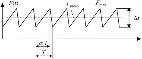
FIGURE 2. The model of steady-state ice force.
Among them, Fmax is the extreme value of ice force, which can be taken as the extreme value of static ice force; ΔF = qFmax,q is 0.1–0.5, where 0.4 is taken here; Fmean is the average value of ice force; T is the ice force period, which can be approximated as the natural period of the structure of the calculation; α is the loading stage coefficient, where 0.8 is taken here.
The calculation of the extreme static ice force uses the formula given in the API RP-2N specification:
Among them, k is the reduction factor, where 0.7 is taken here; D and h represent the diameter of the structural leg and the ice thickness; σc represents the uniaxial compressive strength of the ice.
When the ice speed was fast, irregular and random ice forces were formed, causing structural vibration.
Use ANSYS transient dynamics analysis, the displacement and acceleration time history curves of the structure under steady state (extreme ice thickness 45 cm) and random dynamic ice force was obtained, as shown in Figures 3, 4.
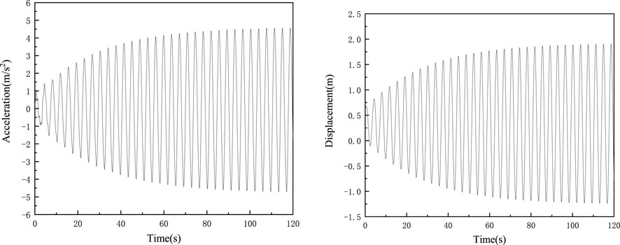
FIGURE 3. The acceleration and displacement response of wind turbine room under steady-state ice force.
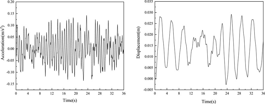
FIGURE 4. The acceleration and displacement response of wind turbine room under random ice force.
The results show that, compared with the steady-state ice force, the structural response under random ice force (10 cm ice thickness) is smaller, but it cannot be ignored. Under extreme steady-state ice forces, the vibration acceleration on top of the foundation reached 4.198 m/s2 and the displacement reached 1.801 m, Large vibration and upper deformation pose a greater threat to the structure itself and electromechanical equipment, and control measures need to be taken.
Based on the structural vibration control theory, and considering the towering and flexible structural characteristics of offshore wind turbines, a damping layer vibration isolation control scheme suitable for offshore wind power structures was proposed, and the structural model was simplified.
A damping and vibration isolation layer was set between the top of the wind turbine tower and the wind turbine head, the specific location was to replace a section of the tower connecting the tower with the unit on the top, and use a flange to connect it. The damping vibration isolation layer was mainly composed of a flexible vibration isolation support and a damping energy dissipation device, as shown in Figure 5. Among them, 1 is connected flange, 2 is spherical hinge, 3 is viscous damper, and 4 is flexible vibration isolation support, the device connects the lower part of the nose to the wind turbine foundation tower by bolts. When the wind turbine tower vibrates, the flexible vibration isolation support and viscous damper will swing 360° with the tower axis as the center. Because the lateral stiffness of the vibration isolation support was relatively small, the vibration isolation layer of the structure was vibrated horizontally. The relative deformation between the layers was larger, so the deformation of the vibration isolation support was limited by setting the damping energy dissipation device.
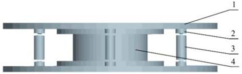
FIGURE 5. The schematic diagram of damping vibration isolation layer.
The concentrated deformation of the vibration isolation layer and the damping energy dissipator dissipated the input energy of the structure, achieve the purpose of reducing the vibration response to the structure, and protect the upper machine head equipment and reduce the fatigue damage to the structure. In the analysis, the damping and stiffness was mainly considered, and the combin14 spring element was used for simulation.
According to the calculation in Section 2.1, the first and second frequencies of the fan structure are 0.2717Hz and 0.2719 Hz respectively, and the offset of the center of mass mainly affects the first and second vibration modes and frequencies. Because the difference between the first and second frequencies is very small, it shows that the offset of the center of mass of the nose has little influence on the whole. Therefore, the structure of the fan is simplified to two degrees of freedom, without considering the influence of the offset of the center of mass of the nose, so as to calculate the stiffness and damping of the damping vibration isolation system.
After the damping isolation layer is applied, the structure is simplified into a three-degree-of-freedom energy dissipation and vibration reduction system, as shown in Figure 6. The lower foundation part of the structure is simplified into a mass point m1, its stiffness and damping coefficient are k1 and c1 respectively; a damping vibration isolation layer is set between the tower top and the wind turbine head, the stiffness and damping coefficient of the vibration isolation layer are k3 and c3 respectively; the wind turbine tower was simplified to a concentrated mass m3, its stiffness and damping coefficients are k2 and c2 respectively; the wind turbine head was simplified to a concentrated mass m3.
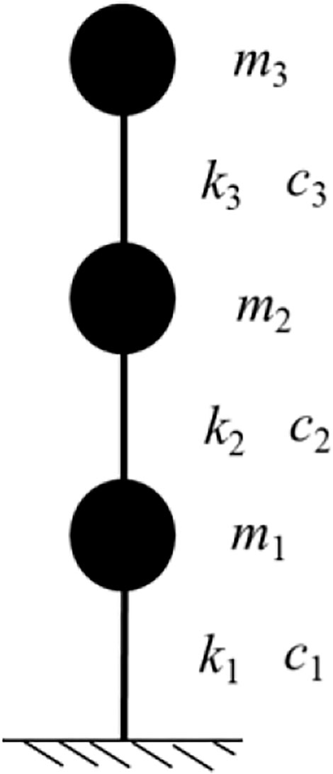
FIGURE 6. The simplified model of damping vibration isolation system.
The parameters of the simplified model are shown in Table 2.
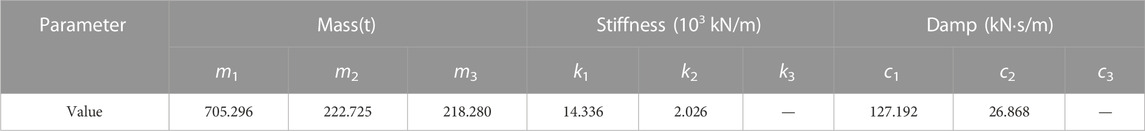
TABLE 2. The parameters of vibration isolation system simplified model.
The diaphragm stiffness k3 and damping coefficient c3 need to be analyzed and designed according to the control conditions of the vibration isolation system of the structure.
The damping ratio is an important parameter for dynamic calculations of structures, and it is also an important index to measure the energy dissipation of structures. Therefore, it is also regarded as an important metric to characterize the effect of vibration reduction schemes. The equivalent system of the structural damping and vibration isolation system model for offshore wind turbine is shown in Figure 7.

FIGURE 7. The equivalent system of damping vibration isolation simplified model.
The vibrational differential equations for multi-degrees of freedom systems can be expressed as:
Among them, M is the mass matrix, C is the damping matrix, K is the stiffness matrix, and F(t) is the external load on the structure. Isolate each mass point and perform force analysis to obtain the following matrix form:
The linear vibration of the structure can be obtained by the superposition of the various modes, so the real mode vibration type matrix of the structure Φ is introduced:
Among them, ϕi is the order i vibration type of the system.
Order:
Among them, Mn, Kn, Cn, and Fn(t) represent the generalized mass, generalized stiffness, generalized damping, generalized load of the order n vibration type respectively.
Introduced the damping ratio:
In formula
The eigenvalue expression of the structural vibration differential equation is:
Based on MATLAB programming, the expression of structural vibration mode and its frequency can be found, because the vibration pattern and frequency expression is not listed here. From Eq. 11, the first vibration type damping ratio of the system is expressed as:
The relative displacement between the damping and vibration isolation layers should not be too large. If the relative displacement between the layers is too large (the stiffness is too small), it will cause a large horizontal deformation between the nose of the offshore wind turbine structure and the wind turbine tower, which is not conducive to the safe operation of the offshore wind turbine structure. The stiffness k3 and damping coefficient c3 of the damped vibration isolation layer are the two key parameters for the design of the vibration isolation layer.
According to Eq. 13, the first mode damping ratio ξ1 can be obtained as the expression of the damping coefficient c3 and the stiffness coefficient k3 of the damping vibration isolation layer. In order to facilitate calculation and analysis, while considering that the stiffness design of the vibration isolation layer should match the stiffness of the tower at the location of the vibration isolation layer, the stiffness coefficient k3 of the damping vibration isolation layer was expressed as a multiple of the wind turbine tower stiffness coefficient k2 for analysis.
Figure 8 shows the variation law between the first mode damping ratio ξ1 of the structure and the damping coefficient c3 of the damping vibration isolation layer under different damping vibration isolation layer stiffness.
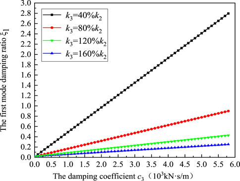
FIGURE 8. The relation between damping ratio and damping coefficient of vibration isolation layer.
The change of ξ1 with c3 shows a linear relationship, and when k3 increases, the rate of change of ξ1 decreases.
When the modal damping ratio of the structure is greater than 0.2, the damping stiffness of the structure was increased, and the damping coefficient increases significantly, which is difficult to achieve, and the damping effect of the damping vibration isolation layer will no longer be obvious (LONG et al., 2001). Therefore, the first mode damping ratio ξ1 of the damping vibration isolation system is taken as .2 in the analysis.
The first order natural frequency of the flexible wind turbine structure should meet the passing frequency P-3P of the wind turbine blade (p = r/60, r is the blade speed, the unit is r/min, here is 12 r/min), Table 3 shows the first order fundamental frequency corresponding to different stiffness coefficients of the wind turbine damping vibration isolation system and the relative difference with the fundamental frequency of the original structure are obtained.
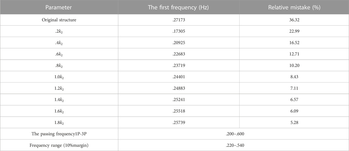
TABLE 3. The first frequency of damping vibration isolation system under different stiffness coefficients.
It can be seen that with the increase in the damping coefficient k3, the first-order fundamental frequency of the wind turbine damping vibration isolation system increases and continues to approach the original structure; when k3≧0.6 k2, the first-order fundamental frequency satisfies the passage frequency range of the structural blade and was compared with the original structure base frequency, the relative frequency difference is small; therefore, considering that the dynamic characteristics of the overall structure meet the requirements, the stiffness coefficient of the damping isolation layer should be at least 0.6 times the stiffness coefficient of the tower.
When k3 and ξ1 are determined, the values of c3 are obtained.
Figure 9 shows the relationship between the damping coefficient c3 and the stiffness ratio. With the increasing stiffness ratio, c3 increases accordingly.
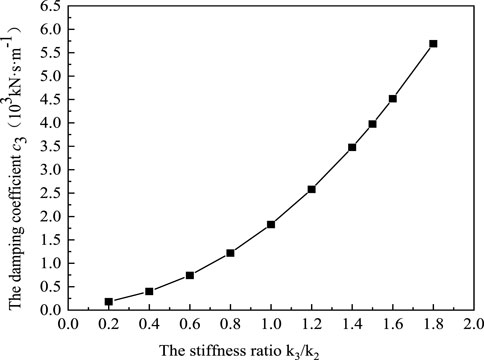
FIGURE 9. The relation between damping coefficient and stiffness ratio of vibration isolation layer.
Meanwhile, in order to clarify the effect of the stiffness parameter k3 on the damping effect of the offshore structure, choose k3 at 0.6 k2(Case1), 0.8 k2(Case2), 1.0 k2(Case3), 1.2 k2(Case4), 1.4 k2(Case5), 1.6 k2(Case6), analyses the damping effect under different parameters, and the calculation parameters of the simplified model are shown in Table 4.

TABLE 4. The calculation parameters of damping vibration isolation system simplified model.
Analyze and calculate the dynamic response to the single pile offshore wind turbine structure under steady ice force and random ice force after adding the damping vibration isolation layer, and use ηi to evaluate the vibration control effect under different parameters, and further clarify the relevant parameters of the vibration isolation layer, among them, ηi = 1-iAfter control/iBefore control, i represents the root mean square value of acceleration and displacement response. The larger the value, the better the control effect.
Figure 10 shows the acceleration and displacement response time history of the wind turbine head before and after the addition of the vibration isolation layer under the action of steady-state ice force. The analysis shows that after adding the damped vibration isolation layer, the top displacement and acceleration response amplitude of the structure is greatly reduced, and the vibration isolation system has a good control effect.
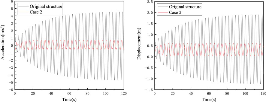
FIGURE 10. The acceleration and displacement control effectiveness when stiffness ratio is .8 under steady-state ice force.
Figure 11 shows the control effect of different parameters under the action of steady-state ice force.
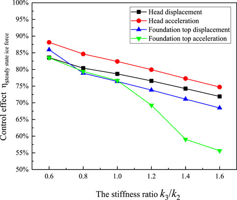
FIGURE 11. The control effectiveness of different stiffness ratios under steady-state ice force.
When under the steady state ice, the damping vibration isolation layer stiffness coefficient k3 is greater than .6 k2, a good control effect can be achieved, and the control effect is greater than 50%; the larger the k3 is, the worse the control effect. At the same time, considering that the inter-layer displacement of the damping vibration isolation layer should not be too large, the stiffness should not be too small.
Figure 12 shows the acceleration and displacement response time history of the wind turbine head before and after the addition of the vibration isolation layer under the action of random ice force. The analysis shows that after adding the damped vibration isolation layer, the top displacement and acceleration response amplitude of the structure decreases, and the vibration isolation system has a better control effect.
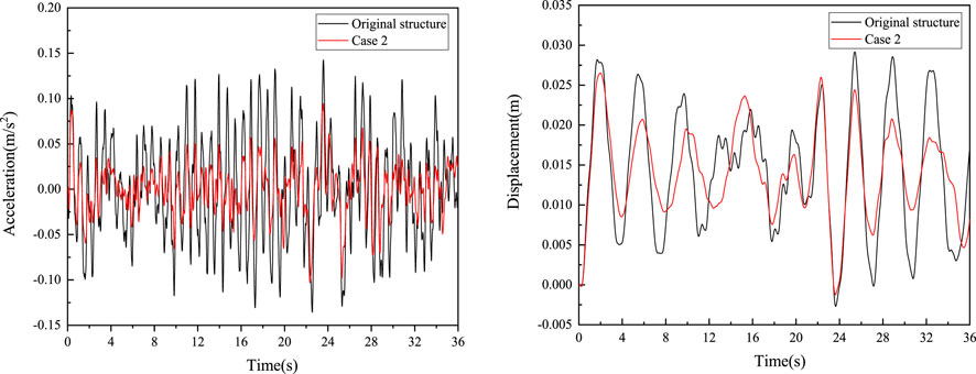
FIGURE 12. The acceleration and displacement control effectiveness when stiffness ratio is .8 under random ice force.
Figure 13 shows the control effectiveness of different parameters under the action of random ice force.
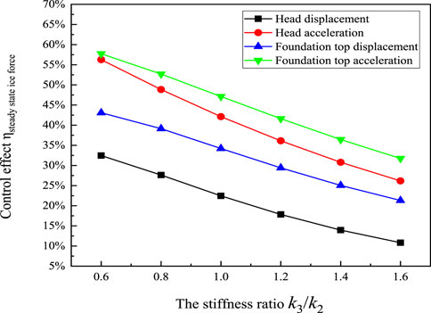
FIGURE 13. The control effectiveness of different stiffness ratios under random ice force.
Compared with the steady state ice, the damping vibration isolation layer under random ice force has a lower control effect on the structure response, and the control effect is less than 60%; the displacement control effect is lower than the acceleration control effect; and the larger the k3, the worse the control effect. Therefore, the stiffness coefficient k3 should not be too large; but at the same time, considering that the inter-layer displacement of the damping vibration isolation layer should not be too large and the stiffness should not be too small, it is recommended to select the damping vibration isolation layer stiffness k3 to be 1.0–1.4 times the tower stiffness k2.
Based on the above analysis, considering the effects of steady state and random ice forces, it is recommended to select the stiffness k3 of the damping vibration isolation layer to be with in this 1.0–1.4 range of times the tower stiffness k2, and the corresponding damping coefficient c3 is 1828.78–3476.98 (kN·s/m).
Offshore wind turbine in cold regions faced the greater threat of sea ice and under the action of sea ice the structure will have obvious ice-induced vibration. Therefore, which is not conducive to the safe operation of wind turbines and it is essential to take corresponding control measures to achieve structural ice vibration control. In this paper, facing the offshore single-pile wind turbine structure in cold regions and the ice vibration control scheme of damping vibration isolation was proposed. Based on numerical calculation, the vibration control effect under different ice force excitation was analyzed, and the relevant parameters of the damping vibration isolation layer was clarified. The main conclusions are as follows:
1) The single-pile wind turbine has a simple structure, the tower and upper nacelle are supported on the upper part of the single-pile foundation. Compared with the traditional marine engineering structure, the wind turbine structure has a larger diameter at the waterline, a higher height, and a mass concentration on the top with the small fundamental frequency, and it is a typical high-rise flexible structure. The structure produces a relatively obvious dynamic response under the action of sea ice, which poses a non-negligible threat to the structural safety and normal operation of the wind turbine. Especially under the action of steady-state ice force, the large vibration and displacement of the nose position poses a greater threat to the structure and the electromechanical equipment, and it is necessary to take relevant control measures.
2) Damping vibration isolation could effectively reduce the influence of external excitation on the structure, aiming at the towering and flexible structural characteristics of offshore wind turbines. So that, a damping layer vibration isolation control scheme suitable for offshore wind power structures is proposed. A damping isolation layer is set between the top of the wind turbine tower and the wind turbine head, and based on the vibration control theory, a simplified calculation model of the wind turbine three-degree-of-freedom damping isolation system was established.
3) The analysis shows that when the stiffness coefficient of the vibration isolation layer is at least 0.6 times to the tower stiffness coefficient, the dynamic characteristics of the damping vibration isolation system are similar to the original structure and meet the design requirements. The first mode damping ratio ξ1 of the damping vibration isolation system and the change of layer damping coefficient showed to be a linear relationship, and as the stiffness of the vibration isolation layer increases and the rate of change of ξ1 decreases. Moreover, in order to prevent the lateral displacement of the damping vibration isolation layer from being too large, the stiffness of the vibration isolation layer should not be too small. When the damping ratio of the first mode was greater than .2 and if the damping stiffness of the structure increase and that will increase the damping coefficient significantly. On the other hand, the increase in damping will decrease the damping effect of the damping isolation layer. Therefore, the ice vibration control effect of the damping vibration isolation system under different vibration isolation layer parameters when the damping ratio .2 was measured and calculated, the results show that the damping vibration isolation layer could play a better structural displacement and acceleration response control effect under both steady-state ice force and random ice force. That was the greater the stiffness of the damping vibration isolation layer, the worse the control effect, and the stiffness of the vibration isolation layer should not be too large. Comprehensive analysis suggests that the stiffness of the damping isolation layer should be within 1–1.4 times ranges the stiffness of the wind turbine tower.
4) This wok proposed a vibration isolation layer control method for the sea ice loads and investigated the influences, whether the vibration damping device could play a better control effect under the action of wind load still needs in-depth analysis. At the same time, the engineering applicability of the anti-icing device needs to be further studied.
The original contributions presented in the study are included in the article/Supplementary Material, further inquiries can be directed to the corresponding author.
Conceptualization, ZB, DR, WG, and ZD; data curation, ZB, DR, WG, and WGu; formal analysis, ZB, DR, WG, and ZD; funding acquisition, ZD; methodology, ZB, WG, and ZD; writing—original draft, ZB and WG; writing—review and editing, ZB, DR, WG, WGu, and ZD. All authors have read and agreed to the published version of the manuscript.
This study was supported by the National Natural Science Foundation of China (52071055), and Innovation team of colleges and universities in Liaoning Province (LT2019004).
Author ZB and WG were employed by PowerChina Huadong Engineering Co., Ltd. Author DR and WGu studied in Dalian University of Technology. Author ZD was employed by Dalian University of Technology.
No conflict of interest exits in the submission of this manuscript, and manuscript is approved by all authors for publication.
All claims expressed in this article are solely those of the authors and do not necessarily represent those of their affiliated organizations, or those of the publisher, the editors and the reviewers. Any product that may be evaluated in this article, or claim that may be made by its manufacturer, is not guaranteed or endorsed by the publisher.
Balendra, T., Wang, C. M., and Cheong, H. F. (1995). Effectiveness of tuned liquid column dampers for vibration control of towers. Eng. Struct. 17 (9), 668–675. doi:10.1016/0141-0296(95)00036-7
Chen, X., Wang, L. Y., Song, A., and Zheng, C. B. (1995). Field experimental study on vibration reduction of TLD water tank. Aata Oceanol. Sin. Chin. 17 (2), 140–144.
Clough, H. F., and Vinson, T. S. (1986). Ice forces on fixed conical structures. Proceedings of the 5th International Offshore Mechanics and Arctic Engineering Symposium, Tokyo, Japan.
Colwell, S., and Basu, B. (2009). Tuned liquid column dampers in offshore wind turbines for structural control. Eng. Struct. 31 (2), 358–368. doi:10.1016/j.engstruct.2008.09.001
Cui, Q. (2011). Study on vibration control of offshore wind turbines by means of pendulum damper. Dalian, China: Dalian University of Technology.
Karna, T., Izumiyama, K., Yue, Q. J., Yan, Q., Guo, F., Xu, N., et al. An upper bound model for self-excited vibrations. Proceedings of the 19th International Conference on Port and Ocean Engineering under Arctic Conditions, Dalian, China, January 2007: 177–189.
Long, X., Wu, B., and Ou, J. P. (2001). Analysis of damping effect on vibration reduction of the aseismic structure. World Inf. Earthq. Eng. 17 (1), 40–45.
Murtagh, P. J., Ghosh, A., Basu, B., and Broderick, B. M. (2008). Passive control of wind turbine vibrations including blade/tower interaction and rotationally sampled turbulence. Wind Energy 11 (4), 305–317. doi:10.1002/we.249
Ou, J. P., Long, X., Xiao, Y. Q., and Wu, B. (2002). Damping isolation system and its vibration-suppressed effectiveness analysis for offshore platform jacket structures. Earthq. Eng. Eng. Vib. 22 (3), 115–122.
Sacki, H., Ono, T., Nakazawa, N., Sakai, M., and Tanaka, S. (1986). The coefficient of Friction between sea ice and various materials used in offshore structures. J. energy Resour. Technol. 108 (1), 65–71. doi:10.1115/1.3231243
Wana, Y. L., Yue, Q. J., Bi, X. J., and Shi, Z. M. (2012). Ice-induced vibration control effectiveness evaluation for an offshore platform based on a field monitoring. J. Vib. Shock 31 (7), 39–45.
Wei, J. S., Wang, L. Y., and Chen, X. (1997). Feasibility study of adding viscoelastic energy dissipation slant brace to reduce ice vibration on JZ20-2 MUQ platform jacket. Chin. offshore oil gas(engineering) 9 (6), 8–13.
Woude, C., and Narasimhan, S. (2014). A study on vibration isolation for wind turbine structures. Eng. Struct. 60, 223–234. doi:10.1016/j.engstruct.2013.12.028
Yang, Y., and Gui, W. M. (2010). The future trend of China wind turbine generation. Int. Mechatronics Technol. 13 (5), 41–43.
Yue, Q. J., Zhang, L., Zhang, W. S., and Karna, T. (2009). Mitigating ice-induced jacket platform vibrations utilizing a TMD system. Cold regions Sci. Technol. 56 (2), 84–89. doi:10.1016/j.coldregions.2008.11.005
Zhang, D. Y., Wang, G. J., Wang, S. F., Tong, B. L., Yue, Q. J., and Luo, C. X. (2018). Ice-resistant performance analysis of offshore wind turbine foundation in ice zone. J. ship Mech. 22 (5), 615–627.
Zhang, L., Yue, Q. J., Zhang, W. S., Fan, Z. L., and Liu, X. H. (2010). Measurement method for equivalent damping force of tuned mass damper (TMD). J. Dalian Univ. Technol. 50 (2), 162–166.
Zhang, L., Zhang, W. S., and Yue, Q. J. (2007). Experimental research on mitigation of offshore platform induced by ice excitation with absorbed damper. China offshore Platf. 22 (5), 33–37.
Keywords: wind turbine foundation, ice-induced vibrations, vibration mitigation, damping vibration isolation, self-excited vibration
Citation: Baofeng Z, Rui D, Gang W, Guojun W and Dayong Z (2023) Mitigation of ice-induced vibrations for wind turbine foundation using damping vibration isolation. Front. Mater. 9:1117959. doi: 10.3389/fmats.2022.1117959
Received: 07 December 2022; Accepted: 28 December 2022;
Published: 11 January 2023.
Edited by:
Yunlai Zhou, Xi’an Jiaotong University, ChinaReviewed by:
Nianzhong Chen, Tianjin University, ChinaCopyright © 2023 Baofeng, Rui, Gang, Guojun and Dayong. This is an open-access article distributed under the terms of the Creative Commons Attribution License (CC BY). The use, distribution or reproduction in other forums is permitted, provided the original author(s) and the copyright owner(s) are credited and that the original publication in this journal is cited, in accordance with accepted academic practice. No use, distribution or reproduction is permitted which does not comply with these terms.
*Correspondence: Zhang Dayong, emhhbmdkeUBkbHV0LmVkdS5jbg==
Disclaimer: All claims expressed in this article are solely those of the authors and do not necessarily represent those of their affiliated organizations, or those of the publisher, the editors and the reviewers. Any product that may be evaluated in this article or claim that may be made by its manufacturer is not guaranteed or endorsed by the publisher.
Research integrity at Frontiers
Learn more about the work of our research integrity team to safeguard the quality of each article we publish.