 Jian Zhang
 Lidong Yang
- Northeast Electric Power Design Institute Co., Ltd of China Power Engineering Consulting Group, Changchun, China
Introduction: The mechanical properties of joints have a significant impact on the dynamic response of transmission tower structures.
Methods: Considering bolt slip, the numerical model of the transmission tower K-joint is established. The mechanical properties of K-joints are studied from three aspects: failure mode, load-displacement hysteretic curve, and stiffness degradation by numerical method. The effects of bolt preload, friction coefficient, and member strength on the hysteretic properties of the K-joint are analyzed.
Results: The results show that due to the complexity of K-joints, bolt slip will lead to the reduction of ultimate bearing capacity and the change of failure position. In order to accurately obtain the mechanical properties of K-joints, the influence of bolt slip should be considered in the research process; The plumpness of load-displacement hysteretic curve is greatly affected by parameters; The stiffness of K-joints degenerates with the increase of loading times.
Discussion: The results provide a reference for the mechanical analysis of the transmission tower.
1 Introduction
Transmission towers in service will be subjected to earthquakes, ice or wind loads and other loads, which may lead to the destruction of the tower, affect the power supply and thus destroy the normal operation of society (Li et al., 2021). In order to prevent these disasters, it is necessary to obtain the accurate response of transmission towers under loads (Li et al., 2022). As the main force bearing part of the transmission tower, the mechanical properties of the joint have a significant impact on the dynamic response of the whole structure. Angle steel transmission towers are mostly connected by bolts, and in order to facilitate installation, the bolt hole diameter is usually larger than the bolt shank, in the process of transmission tower vibration members will occur relative sliding, that is, bolt slippage. Bolt slip will not only cause the difference of members failure mode but also lead to the change in joint stiffness (An et al., 2019). Ungkurapinan et al. (2003) studied the bolt slip phenomenon through experiments and proposed a mathematical model of bolt slip based on the test results. Through the combination of experiment and simulation (Jiang et al., 2011; Jiang et al., 2017), introduced bolt slip into the overall analysis of the transmission tower, and found that bolt slip had an impact on the ultimate bearing capacity, failure mode and displacement response of transmission tower. Wang et al. (2015) studied the influence of bolt slip on the structural response of transmission tower under uneven foundation settlement by numerical simulation. The results show that bolt slip not only increases the deformation of the tower, but also causes the redistribution of internal forces. Jiang et al. (2016) studied the influence of bolt slip uncertainty on the internal force of transmission tower by the LHS (Latin hypercube sampling) method. Yang et al. (2017) analyzed the influence of parameters such as initial torque and bolt hole diameter on the load-deformation curve of the joint through the tension test and numerical simulation of the bolt joint. The results show that when analyzing the tower structure, if the joint slip effect is ignored, it will cause higher axial stiffness. Ye et al. (2017) established an improved bolt slip model and accurately analyzed the behavior of the tower under external forces. The results show that the degree of influence of bolt slip is related to load. de Souza et al. (2021) performed reliability assessment of existing transmission line towers considering mechanical model uncertainties, their results showed that the bolt slip could affect the failure of the tower. Gan et al. (2021) performed monotonic tests to study the joint slip effect, and proposed a simplified multilinear bolt slippage model.
However, the above studies only consider the one-way slip of bolts, which is only applicable to the static analysis of transmission towers. In reality, the joints of transmission towers are often subjected to repeated loads during vibration, and the bolts will slip back and forth. The one-way slip model cannot accurately reflect the dynamic response of the tower. Yaghoobi and Shoddshtari. (2018) studied the influence of parameters such as bolt arrangement and bolt diameter on the mechanical behavior of joints under cyclic loading by conducting joint tests of 51 groups of wind turbine lattice towers. The results show that the above parameters can affect the hysteretic behavior of joints. Ma and Bocchini (2019) analyzed the stress state of the joint at each stage under cyclic loading, and proposed a hysteretic model of single bolted joints considering bolt slip. Considering different bolt clearances, Jiang and Dong. (2020) established a finite element model of double-limb lap joints and analyzed the hysteretic characteristics of the joints. Li et al. (2020) studied the mechanical properties of typical bolted joints under cyclic loading through numerical simulation, and analyzed the influence of parameters such as initial clearance and initial torque on the hysteretic behavior of joints. The results show that the influence of bolt reciprocating slip should be considered. Ebrahimi et al. (2022) performed test study to obtained the load-deformation curves of joint under cycle loading, and then proposed a mathematical formula to describe the load-deformation curves. Lu et al. (2018) Studied the influence of the cycle loading on the joint slip by tests, and the results showed that bolt-slip load decrease with the increase of the cyclic loading.
Nevertheless, the above studies are only for the lap bolt joints in transmission towers. In the transmission tower structure, the K-joint is a very common form of joints, just like the lap joint, and compared with the lap joint, the stress state of K-joint is more complex. Zhao et al. (2014) deduced the initial rotational stiffness calculation model of K-joints and modified the model according to the test results. Yang et al. (2018) introduced the axial force coefficient of bolt joints into the traditional unit load method, and verified the accuracy of the improved method by experimental results. The results show that reducing the bolt clearance can decrease the deformation of K-joint of UHV cat-head transmission tower. Wang et al. (2019) studied the detached tubular K-joints through experiments and the results show that the separation distance of the gusset plate can affect the failure mode of the joint. Li et al. (2021) studied the influence parameters of the moment-rotation hysteresis curve of K-joints by establishing the finite element model (FEM) of K-joints. The results show that the failure mode of K-joints is related to the bolt grade and steel strength.
A review of the abovementioned works indicates that the existing research on bolt slip is aimed at bolt lap joints, and there is still a lack of research on bolt slip of K-joints, especially the mechanical properties under cyclic loading. Therefore, the mechanical properties of K-joints are studied by numerical method in this paper, and the effect of bolt slip on the hysteretic properties of K-joints is emphatically discussed. In Section 2, the numerical model and simulation schemes of K-joints are introduced. In Section 3, the simulation results are analyzed from the loading mode, load-displacement hysteresis curve and joint stiffness. And finally, Section 4 concludes the study.
2 Numerical simulation of the K-joint
2.1 The FEM of the K-joint
In this paper, a large-scale commercial finite element software ANSYS is used to simulate a K-joint of a transmission tower, and the FEM of the K-joint was established by 3D 8-node solid element SOLID185, as shown in Figure 1. There are five types of contact pairs in the model, which are the contact between the main angle steel and the gusset plate, the contact between the branch angle steel and the gusset plate, the contact between the nut and the steel member, the contact between the bolt head and the steel member, and the contact between the bolt shank and the bolt hole. The 3D surface-to-surface contact element CONTA173 and the 3D target element TARGE170 are used as the contact element and the target element, respectively. And the bolt pretension force is applied by the preload element PRETS179. Hexahedral mesh is adopted in the model, and refined division operation is carried out at the contact part of steel members. The elastoplastic model with a strengthened section is adopted for the constitutive relationship of members and bolts, as shown in Figure 2. In Figure 2, E is the elastic modulus, εy is the yield strain, εu is the ultimate strain, fy is the yield stress; fu is the ultimate stress.
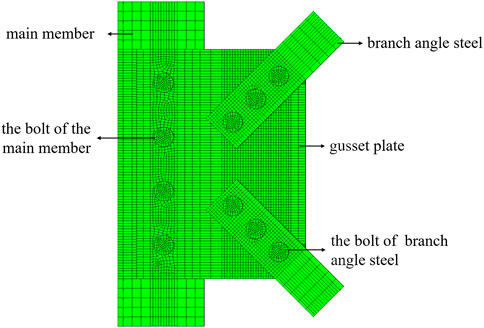
FIGURE 1. Finite element model of the K-joint.
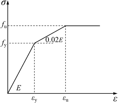
FIGURE 2. Constitutive relation of steel.
2.2 Simulated conditions
In this paper, simulations of twelve loading scenarios are carried out. The thickness of each component in this model is 10 mm, in which the main material is L160 × 10 angle steel and the branch member is L80 × 10 angle steel. The effects of preload force, friction coefficient of the component, eccentricity, bolt hole diameter, strength of connector and bolt grade on the hysteretic performance of K-joints are studied, as listed in Table 1. In order to study the effect of bolt slip of K-joint, different loading modes were applied to Group A and Group B, respectively, in which tension compression cyclic load is applied to single branch angle steel of Group A, and tension compression cyclic load is applied to double branch angle steels of Group B, as shown in Figure 3. According to the Chinese code, the load is first loaded according to 25%, 50%, and 75% of the yield load, and each stage is cycled once. After the yield is reached, it is gradually increased according to 10% of the ultimate load, and each stage is cycled three times (Zhang and Li, 2017).
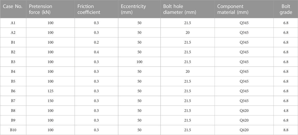
TABLE 1. Simulation scheme.
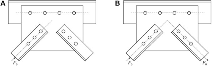
FIGURE 3. Loading mode of Group (A) and Group (B).
3 Result analysis
3.1 Influence of loading mode
When the single branch angle steel of the K-joint is subjected to cyclic loading, the stress state of the K-joint is equivalent to the bolt lap joint. However, when double branch angle steels are subjected to cyclic loading because the resultant force of branch angle members bearing the load does not pass through the centroid of the bolt group on the main angle steel, the moment will be generated at the centroid of the bolt group, resulting in the sliding of the branch angle steel. Meanwhile, the gusset plate will rotate by eccentric force. In this state, the stress state of the K-joint is more complicated and it is also more consistent with the actual stress state of the K-joint. The load-displacement hysteresis curves under two different loading conditions are shown in Figure 4. The curve takes the displacement of the loaded branch angle steel as the horizontal axis and the load as the vertical axis. It can be seen that the ultimate load and failure position of Group B are different from those of Group A.
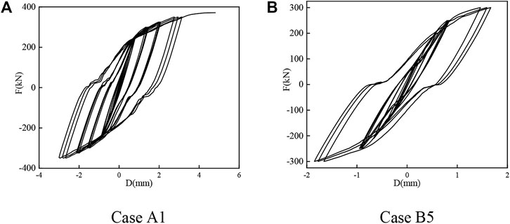
FIGURE 4. Load-displacement curves of the K-joints. (A) Case A1. (B) Case B5.
The ultimate load of Case A1 is 371.25 kN, the ultimate load of Case B5 is 300 kN, and the ultimate load is reduced by 23.75%. The reason for this phenomenon is that when the single branch angle steel of the K-joint bears the load F0, the resultant force at the centroid is only
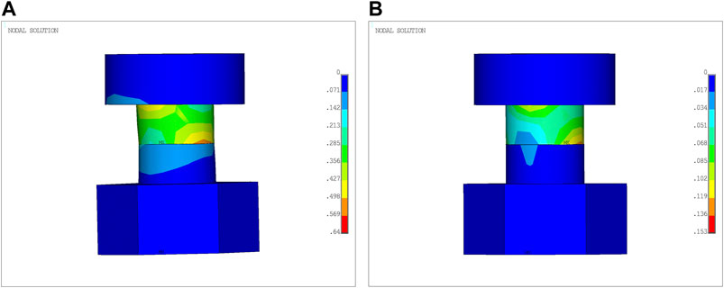
FIGURE 5. Bolt plastic strain of Case A1. (A) the bolt of branch angle steel, (B) the bolt of main angle steel.
When branch angle steels on both sides of the K-joint are subjected to a load F0 of one tension and one compression at the same time, the resultant force at the centroid is
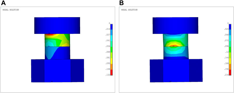
FIGURE 6. Bolt plastic strain of Case B5. (A) the bolt of branch angle steel, (B) the bolt of main angle steel.
However, when the bolt slip is not considered, the ultimate load of K-joints under the two loading methods is 375 kN and 373.8 kN, respectively, with a difference of 0.32%. At this time, the loading method has little effect on the ultimate load. Therefore, the main difference between Case A1 and Case B5 is due to the influence of bolt slip on the K-joint. Figure 7 shows the load-displacement hysteresis curve without considering the bolt slip. It can be seen that when the bolt gap is not considered, the hysteresis curve is fusiform and full in shape, which also shows that it is necessary to consider the bolt slip of the K-joint.
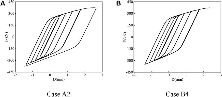
FIGURE 7. Load-displacement curves of the K-joints. (A) Case A2, (B) Case B4.
3.2 Load-displacement hysteresis curves
The trend of structural stiffness variation under cyclic loading can be obtained from the hysteretic curve. It can be seen from Section 3.1 that the bearing capacity of double branch angle steel loading is lower than that of single branch angle steel loading, and the K-joint is in the most unfavorable stress state. Therefore, this section mainly analyzes the hysteresis curve of double branch angle steel loading.
The hysteresis curve of each working condition is shown in Figure 8. It can be seen that the fullness of the hysteresis curve is affected by the parameters such as bolt preload, friction coefficient, eccentricity and other parameters. Compared with Figures 8D–F, it can be seen that with the increase of bolt preload, the shape of the hysteresis curve is plumper. This trend is the same as Figures 8A, B, D. The reason for this phenomenon is that increasing the preload of the bolt can make the components of the bolt connection area more closely fit, to a certain extent, the effect of increasing the friction force is achieved, so more energy is dissipated during the cycle. Figures 8C, D show the hysteretic curves of the joints with different eccentricities. When the eccentricity increases from 50 mm to 100 mm, the ultimate load decreases from 300 kN to 275.4 kN. This is because the same load can produce greater moment when the eccentricity increases, and the rotation angle of the gusset plate will also increase, resulting in the failure of the joint. However, it has little effect on the shape of the hysteresis curve, because the load-displacement curve analysis focuses on the deformation of the branch angle steel rather than the rotation of the gusset plate. Compared with Figures 8G–I, the bolt grade is increased from 4.8 to 8.8, and the ultimate load is 239.25, 350 and 425 kN, respectively, which shows that increasing the bolt grade can effectively improve the bearing capacity of the joint, and meanwhile, the curve becomes more full.
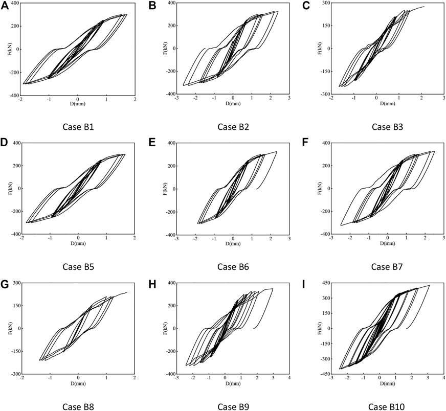
FIGURE 8. Load-displacement curves of the K-joints. (A) Case B1, (B) Case B2, (C) Case B3, (D) Case B5, (E) Case B6, (F) Case B7, (G) Case B8, (H) Case B9, (I) Case B10.
As can be seen from Figure 8, the slope of the load-displacement curve decreases gradually during each cycle, indicating that the stiffness of the joint is degraded and the residual deformation is accumulated. The reason for this phenomenon is the yielding of members and bolts and the slipping of bolts. In addition, in the process of repeated loading, due to the existence of bolt clearance, both the bolt of the main angle steel and the bolt of the branch angle steel will slip a certain distance, which leads to the occurrence of the pinching phenomenon, making the hysteresis curve a pinched anti-S shape. If the clearance between the bolt and the screw hole is eliminated, a welding-like effect will be produced, and the hysteresis curve will also be in a full spindle shape, as shown in Figure 7. This shows that reducing the clearance and avoiding bolt slippage can improve the seismic performance and energy dissipation capacity of the K-joint.
3.3 Rigidity degeneration
According to the Chinese code (China Academy of Building Research, 2015), the secant stiffness Ki under each cycle is calculated by Eq. 1.
where + Fi and -Fi are the load values of the ith forward and reverse peak points; +Xi and -Xi are the displacement values of the ith forward and reverse peak points.
The secant stiffness Ki of the load-displacement curve of each cycle is shown in Figure 9. It can be seen from the figure that the secant stiffness of Case B4 and Case B8 suddenly decreases. As grade 4.8 ordinary bolts are used in Case B8, the shear strength is very low, and the bolts yield earlier, resulting in the early stage of the cycle joint stiffness decreased. Case B4 is similar to welding because there is no clearance. It can be seen from the shape of the hysteresis curve that there is an obvious yield point. When the component reaches yield, the stiffness of the joint will suddenly decrease first and then decrease slowly, while the stiffness degradation of other cases is generally gentle.
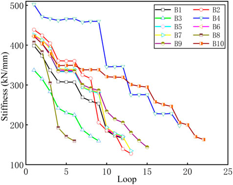
FIGURE 9. Stiffness degradation.
The stiffness of K-joints with larger eccentricity for the same material is generally lower. At the same time, the overall stiffness of the joint can be improved by increasing the strength of the component and upgrading the bolt grade.
In addition, Table 2 shows the initial stiffness K0 of K-joints under different conditions. It can be seen from the table that the initial stiffness of the K-joints in the elastic state has little different.
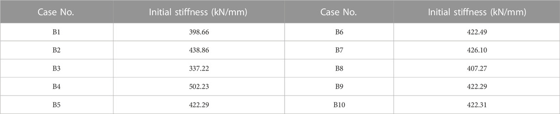
TABLE 2. Initial stiffness of K-joint.
4 Conclusion
In this paper, the influence of bolt slip on the hysteretic characteristics of K-joints under cyclic loading is mainly studied. The following conclusions are obtained from the analysis of failure mode, hysteretic curve and stiffness degradation:
(1) The stress state significantly impacts the bearing capacity of K-joints. The ultimate bearing capacity of K-joints under single branch member loading is much higher than that under double branch members loading. The most unfavorable load condition of K-joints is that one branch member bears tension and the other branch member bears compression.
(2) The loading method affects the failure position of the K-joint. Under single branch angle steel cyclic loading, the bolt of the branch angle steel is first destroyed, while under double branch angle steel cyclic loading, the bolt of the main angle steel is destroyed earlier than the bolt of the branch angle steel due to the greater resultant force.
(3) The existence of clearance not only leads to the decrease of bearing capacity of joints, but also affects the hysteretic performance.
(4) The plumpness of the hysteresis curve can be increased by increasing the preload of the bolt, increasing the strength of the component or reducing the clearance.
(5) With the increase in the number of loading cycles, K-joints show a trend of stiffness degradation. Increasing the strength of the component or the bolt grade can improve the overall stiffness of the K-joint, but the initial stiffness of each case has little difference.
Data availability statement
The original contributions presented in the study are included in the article/supplementary material, further inquiries can be directed to the corresponding author.
Author contributions
JZ Proposed research ideas, was responsible for the establishment and calculation of the finite element model, and wrote the first draft. GW was responsible for the analysis of the results of the paper. LY guided and revised the paper.
Conflict of interest
The authors declare that the research was conducted in the absence of any commercial or financial relationships that could be construed as a potential conflict of interest.
Publisher’s note
All claims expressed in this article are solely those of the authors and do not necessarily represent those of their affiliated organizations, or those of the publisher, the editors and the reviewers. Any product that may be evaluated in this article, or claim that may be made by its manufacturer, is not guaranteed or endorsed by the publisher.
References
An, L., Wu, J., and Jiang, W. (2019). Experimental and numerical study of the axial stiffness of bolted joints in steel lattice transmission tower legs. Eng. Struct. 187, 490–503. doi:10.1016/j.engstruct.2019.02.070
China Academy of Building Research (2015). Specification for seismic test of buildings: JGJ/T 101-2015. Beijing: China Architecture & Building Press.
de Souza, R., Miguel, L., McClure, G., Alminhana, F., and Kaminski, J. (2021). Reliability assessment of existing transmission line towers considering mechanical model uncertainties. Eng. Struct. 237, 112016. doi:10.1016/j.engstruct.2021.112016
Ebrahimi, A., Yaghoobi, S., and Shooshtari, A. (2022). Joint slip formulation for members with double angle section based on experimental results in wind turbine lattice towers. Arabian J. Sci. Eng. 47 (10), 13699–13709. doi:10.1007/s13369-022-06690-z
Gan, Y., Deng, H., and Li, C. (2021). Simplified joint-slippage model of bolted joint in lattice transmission tower. Structures 32 (2021), 1192–1206. doi:10.1016/j.istruc.2021.03.022
Jiang, W., and Dong, X. (2020). Research on hysteresis behavior of bolted joints in transmission tower leg. Chin. J. Constr. Mach. 18 (06), 542–548. doi:10.15999/j.cnki.311926.2020.06.014
Jiang, W., Liu, Y., Chan, S., and Wang, Z. (2017). Direct analysis of an ultrahigh-voltage lattice transmission tower considering joint effects. J. Struct. Eng. 143 (5), 4017009. doi:10.1061/(asce)st.1943-541x.0001736
Jiang, W., Wang, Z., and An, L. (2016). The uncertainty of bolted joint slippage effects on the inner force of lattice transmission towers[J]. Struct. Eng. 32 (04), 42–50. doi:10.15935/j.cnki.jggcs.2016.04.007
Jiang, W., Wang, Z., Mcclure, G., Wang, G., and Geng, J. (2011). Accurate modeling of joint effects in lattice transmission towers. Eng. Struct. 33 (5), 1817–1827. doi:10.1016/j.engstruct.2011.02.022
Li, J., Mcclure, G., and Wang, S. (2021). Ensuring the structural safety of overhead transmission lines by design. J. Aerosp. Eng. 34 (3), 4021010. doi:10.1061/(asce)as.1943-5525.0001245
Li, J., Wang, B., Sun, J., and Wang, S. (2020). Numerical simulation study on hysteresis characteristics of transmission tower bolt joints. J. Northeast. Univ. Nat. Sci. 41 (11), 1633–1639. doi:10.12068/j.issn.1005-3026.2020.11.018
Li, J., Zhang, C., Wang, S., and Yin, S. (2021). Numerical study on the mechanical properties of transmission tower K-joints under cyclic loading. Shock Vib. 2021, 1–11. doi:10.1155/2021/7403365
Li, J., Zhang, X., and Mcclure, G. (2022). Numerical and full-scale test case studies on post-elastic performance of transmission towers. Eng. Struct. 259 (2022), 114133. doi:10.1016/j.engstruct.2022.114133
Lu, C., Ma, X., and Mills, J. (2018). Cyclic performance of bolted cruciform and splice connectors in retrofitted transmission tower legs. Thin-Walled Struct. 122, 264–285. doi:10.1016/j.tws.2017.10.020
Ma, L., and Bocchini, P. (2019). Hysteretic model of single-bolted angle connections for lattice steel towers. J. Eng. Mech. 145 (8), 04019052. doi:10.1061/(asce)em.1943-7889.0001630
Ungkurapinan, N., Chandrakeerthy, S., Rajapakse, R., and Yue, S. (2003). Joint slip in steel electric transmission towers. Eng. Struct. 25 (6), 779–788. doi:10.1016/s0141-0296(03)00003-8
Wang, J., Chen, Y., Guo, Y., Chen, C., and Sun, B. (2019). Experimental study on the mechanical behavior of detached tubular K-joints of narrow foundation transmission towers. Eng. Mech. 36 (1), 66–70.
Wang, P., Chen, H., Zhang, H., Zhou, X., and Ye, M. (2015). Effect of bolt joint on the behaviour of transmission tower with non-uniform settlement. Eng. Mech. 32 (10), 209–219. doi:10.6052/j.issn.1000-4750.2014.03.0212
Yaghoobi, S., and Shooshtari, A. (2018). Joint slip formulation based on experimental results in wind turbine lattice towers. J. Struct. Eng. 144 (6), 04018058. doi:10.1061/(asce)st.1943-541x.0002023
Yang, F., Zhu, B., and Li, Z. (2018). Numerical analysis and full-scale experiment on K-joint deformations in the crank arms of lattice transmission towers. Struct. Des. Tall Special Build. 27 (5), e1448. doi:10.1002/tal.1448
Yang, F., Zhu, B., and Xing, H. (2017). The slip characteristics and parametric study of bolted connections for transmission tower. Eng. Mech. 34 (10), 116–127. doi:10.6052/j.issn.1000-4750.2016.05.0403
Ye, M., Chen, H., Zhang, H., and Zhao, X. (2017). Effect of bolt joints on behaviour of transmission tower under external loads. J. Univ. Sci. Technol. China 47 (06), 498–507. doi:10.3969/j.issn.0253-2778.2017.06.008
Zhang, Y., and Li, Z. (2017). Study on mechanical behavior of multiplanar full-scale joint with composite connection. China Civ. Eng. J. 50 (06), 33–41. doi:10.15951/j.tmgcxb.2017.06.004
Keywords: transmission tower, K-joints, hysteretic characteristics, numerical simulation, bolt slip
Citation: Zhang J, Wu G and Yang L (2022) Numerical study on hysteretic characteristics of transmission tower K-joints. Front. Mater. 9:1116490. doi: 10.3389/fmats.2022.1116490
Received: 05 December 2022; Accepted: 21 December 2022;
Published: 30 December 2022.
Edited by:
Chun-Xu Qu, Dalian University of Technology, ChinaReviewed by:
Li Chuang, Shenyang University, ChinaWenqiang Jiang, North China Electric Power University, China
Copyright © 2022 Zhang, Wu and Yang. This is an open-access article distributed under the terms of the Creative Commons Attribution License (CC BY). The use, distribution or reproduction in other forums is permitted, provided the original author(s) and the copyright owner(s) are credited and that the original publication in this journal is cited, in accordance with accepted academic practice. No use, distribution or reproduction is permitted which does not comply with these terms.
*Correspondence: Lidong Yang, eWFuZ2xpZG9uZzIwMjJAeWVhaC5uZXQ=