 Menglong Cong
 Shanshan Zhang2
95% of researchers rate our articles as excellent or good
Learn more about the work of our research integrity team to safeguard the quality of each article we publish.
Find out more
ORIGINAL RESEARCH article
Front. Mater. , 15 December 2022
Sec. Polymeric and Composite Materials
Volume 9 - 2022 | https://doi.org/10.3389/fmats.2022.1109896
This article is part of the Research Topic Advanced Technologies for Electrical Engineering - Volume II View all 5 articles
When the current passing through a high temperature superconducting (HTS) coil that exceeds a critical value, the properties of the materials which make up the coil will fail, generating large amounts of heat and even causing serious accidents. Aiming at the above safety problem, this paper took three solenoid magnets with different structures as the object, and conducted a simulation study on their electromagnetic performance through finite element method (FEM). The magnetic field intensity H was taken as the dependent variable of the control equations of the physical field. With the aid of the partial differential equation (PDE) interface of the simulation software used, the control equations were easily constructed. The pancake coil wound by many turns of ribbon conductors was abstracted as a bulk-like conductor with the same cross-sectional area. The main idea of this equivalent replacement is to simplify the internal structure of the device without affecting its electromagnetic behavior, which can accelerate the convergence speed of the simulation process and reduce the CPU burden. Models of solenoid magnets with rectangular, trapezoidal and inverted trapezoidal cross sections were established by stacking many pancake coils. The simulation results corresponding to these models show that the solenoid magnet with trapezoidal cross-section has the largest critical current and most uniform density distribution. Such advantages not only reduce the risk of superconducting material failure due to overheating at both ends, but also fully exploit the current carrying capacity of the coil in the middle area of the solenoid.
The phenomenon in which the DC resistance of a material becomes zero is called superconductivity. In 1908, Onnes succeeded in the liquefaction of helium, which allowed the artificial creation of a low temperature environment of 1.15–4.25 K. In 1911, Onnes found that the DC resistance of mercury tends to zero at a temperature of 4.2 K, which opened a new chapter in the study of low-temperature superconductivity (Onnes, 1991). The actual resistance measured experimentally is as low as 10−23 mΩ cm, which can be considered to be zero. So far, more than 5,000 superconducting materials have been discovered, including most metals such as Hg, Pb, Cu, and Ag, and alloys such as NbTi, Nb3Sn, and simple metal compounds can achieve superconductivity at low temperatures (Kunzler et al., 1961; Berlincourt, 1987), but their superconducting critical transition temperature (Tc) is very low. Reducing the ambient temperature to the liquid helium temperature region requires a lot of resources, which restricts the development of superconducting industrial applications. In 1986, Bednorz and Müller (Bednorz and Müller, 1986) found that the LaBaCuO system has superconductivity, and its Tc was increased to 35 K for the first time. This opens up new ideas for the exploration of superconducting materials, and triggers an upsurge in the research of HTS materials. In 1987, Wu (Wu et al., 1987) discovered that the Tc of the YBaCuO system reached more than 90 K, realizing the superconducting state of the conductive material in the liquid nitrogen temperature region. In 1988, Japanese scholars discovered that the critical transition temperature of BiSrCaCu superconductor reached 110 K (Maeda et al., 1988). The continuous discovery of various metal oxide superconductors has opened the upsurge of refreshing high Tc (Kondoh et al., 1988).
In recent years, with the development of HTS materials, their applications in future nuclear fusion reactors (Rajput et al., 2022), high-energy particle accelerators (Jia et al., 2019), nuclear magnetic resonance imaging (Cavanagh et al., 2018), spallation neutron sources (Cummings and Johnson, 2017), and gas sensors (Yang et al., 2020) have become more and more widely. The main applications of HTS strip in the field of electrical and electronic equipment lie in two aspects: superconducting power technology and superconducting magnet technology. Among them, superconducting magnet (Klyukhin et al., 2019) technologies mainly include strong magnetic field magnets, magnetic levitation magnets and superconducting induction heating. On the other hand, superconducting strong electric applications mainly include superconducting cables (Arai et al., 2019), superconducting current limiters (Kar et al., 2012), superconducting transformers (Chen et al., 2018), superconducting generators (Magnusson et al., 2015), superconducting motors (Du et al., 2020) and superconducting energy storage (Zhu et al., 2018).
Compared with many other energy storage technologies, superconducting energy storage has the technical advantages of zero resistance loss, high power density, long life cycle, and high response speed (Shaqsi et al., 2020). Superconducting energy storage strategy can provide high quality and high efficiency power supply for renewable energy power system, so as to reduce the risk of power grid disconnection and collapse caused by sudden voltage rise and sudden drop, and improves the operation safety of power system (Wang et al., 2015). The core component of superconducting energy storage is the superconducting magnet (Mukherjee and Rao, 2019). Since the current capacity of a single strip is difficult to meet the high current-carrying requirements, multiple superconducting strips can be wound into pancake coils as superconducting magnets according to certain rules. Further, many pancake coils can be stacked to obtain a solenoid magnet. The superconducting solenoid coil has large inductance and threshold current, and can achieve near-zero energy storage loss, so it is ideal for efficient and fast energy storage (Indira et al., 2015).
As the second-generation HTS strip, REBaCuO is composed of rare Earth (Rare Earth, Re), barium (Ba), copper (Cu), and oxygen (O) elements. RE is the acronym of rare Earth, including a total of 17 elements of scandium, yttrium and lanthanide (Dadras et al., 2017). Therefore, in the chemical formula of REBaCuO, RE can be replaced by any rare Earth element, such as yttrium (Y), gadolinium (Gd), samarium (Sm), etc. REBaCuO has high critical current density and irreversible magnetic field in liquid nitrogen temperature region. With the improvement of artificial magnetic flux pinning technology (Misko et al., 2012), the in-field current-carrying capacity and magnetic flux pinning force density of REBaCuO HTS strip far exceed other practical superconducting materials. On the other hand, the use of flexible Hastelloy or stainless steel substrate improves its mechanical properties. These advantages make REBaCuO strips break through the application limitations of the first-generation Bi2223/Bi2212 HTS strips, and have wider application prospects in the field of superconducting energy storage.
In this paper, the solenoid magnet wound by REBaCuO strips is taken as the research object, and the geometric structure is optimized through the FEM (Zhao et al., 2014), so as to improve its critical current and make its density reasonably distributed. It should be noted that although there have been some researches of superconducting properties based on FEM have been reported (Guo et al., 2019), the modeling and analysis objects are mainly superconducting strips (Peng et al., 2020) or coil wound by them (Ainslie et al., 2017), rather than solenoid magnet with more complex structures. In Section 2, the core theory of superconducting coil modeling is expounded based upon the Ampere’s law and Faraday’s law, which belong to Maxwell’s equations. Furthermore, combined with the constitutive relationship between electric field intensity and current density, as well as magnetic induction intensity and magnetic field intensity, the H-equation form with only magnetic field intensity as the dependent variable is obtained. In Section 3, the original cake coil model is simplified, and three solenoid electromagnet models with rectangular, trapezoidal and inverted trapezoidal cross sections are established. By changing the diameter of the solenoid, the amount of strips required to build the above models is kept unchanged. The H-equation is imported through the PDE interface provided by the software, and the simulation environment is built. In Section 4, the magnetic flux density and critical current density of the constructed solenoid models is simulated. Based on the obtained data, a comprehensive comparative analysis is realized.
Analytical and numerical methods are commonly used to study the electromagnetic properties of superconductors. For simple geometric structures and uniform physical fields, the analytical method can take advantage of its rapid calculation and convenient optimization analysis. Because the superconducting coil is a complex structure formed by winding many strips, and the strip has the characteristics of anisotropic, its electromagnetic characteristics cannot be expressed by a complete expression. Considering the convergence speed of the iterative process and the complexity of the boundary conditions, the H-equation was used to complete the numerical calculation. The essence of H-equation is Ampere’s law and Faraday’s law of Maxwell’s equations:
In Eqs 1, 2, H is the intensity of magnetic field, J is current density, E is the intensity of electric field and B is the intensity of magnetic induction. By introducing vacuum permeability μ0 and relative permeability μr, the constitutive relationship between B and H can be obtained:
The expression of resistivity ρ can be derived from the E-J relationship of HTS materials:
where Jc represents the critical current density. The expression proposed by Kim (Kim et al., 1963) introduced the dependence of Jc on external magnetic field:
In Eq. 5, Bpara and Bperp are the induction intensity of the external magnetic field parallel to and perpendicular to the wide plane of the superconducting strip. Jc0 represents the critical current density under self-field condition. k, B0 and α are characteristic parameters of the superconducting strip. Combining Eqs 1–5, the Faraday’s law can be rewritten as
As can be seen in Eq. 6, the form of H-equation is simple and clear, including only one dependent variable H. In addition, the boundary conditions of the superconducting magnet model based on this equation are easy to set. In order to construct a 2-D axisymmetric coil model, the cylindrical coordinate system should be introduced. In the cylindrical coordinate system, the current density and the electric field only have the angular components Jφ and Eφ, while the magnetic field strength H contains the radial component Hr and the axial component Hz. Accordingly, Eqs 1, 6 can be rewritten as the following:
The superconducting strips available in the market vary widely in size and characteristics. The simulation research object selected here is SCS4050 produced by Shanghai Superconductor Company1, and its main geometric parameters are listed in Table 1. Figure 1 shows the 2-D axisymmetric model of the pancake coil in column coordinate system and the divided mesh (locally enlarged). The coil model contains 50 turns, with the innermost layer be defined as the first turn. Insulation layer and base material are filled between the adjacent turns of the coil with a space of 400 μm, and the inner diameter of the coil is 200 mm.
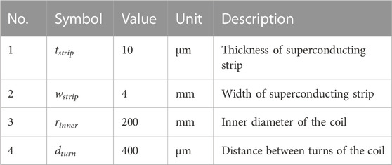
TABLE 1. Geometric parameters of pancake coil.
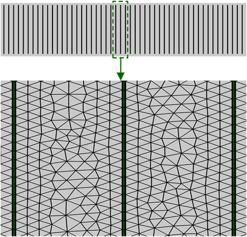
FIGURE 1. 2-D axisymmetric model of the pancake coil and the divided mesh (locally enlarged).
As could be seen in Table 1, the selected superconducting strip has a width (z-direction) to thickness (r-direction) ratio of up to 400, which results in an overly fine grid in the r-direction and burdens the CPU. In addition, because there is no current flowing through the insulating layer between adjacent superconducting strips, so it is not necessary to study the magnetic field distributed there. Therefore, the complex model is simplified to the bulk-like conductor shown in Figure 2, which gives consideration to both the accuracy and speed of simulation. Obviously, the fully mapped structure in Figure 2 has higher mesh quality than the hybrid structure in Figure 1, which combines mapped mesh and free triangle mesh.
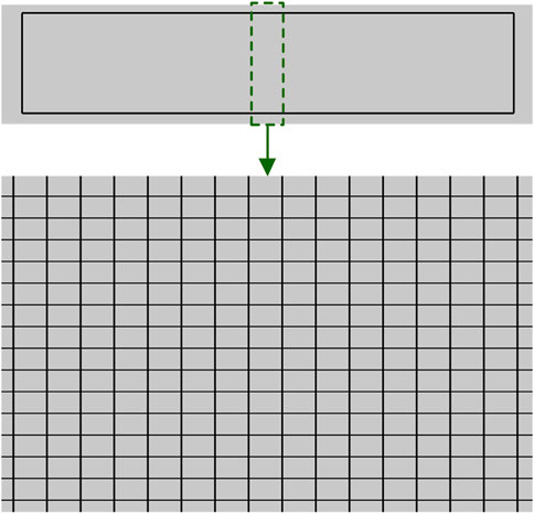
FIGURE 2. Simplified model of the pancake coil and the divided mesh (locally enlarged).
As an important performance index of superconducting magnet, the critical current density represents the maximum current that superconductor can withstand in the superconducting state. According to Eq. 5, the critical current value is determined by the magnetic induction intensity parallel (Bpara) to and perpendicular (Bperp) to the wide surface of the superconducting strip. A solenoid magnet is composed of a series of concentrically stacked pancake coils. Due to the closure and non-uniformity of the magnetic field line, the critical current may change at different heights along the axis of the solenoid, or even at different radial positions of the same pancake. Considering the difference of the critical current in the axial and radial directions of the solenoid, there must be a reasonable structure design to maximize the minimum critical current on the whole coil.
Figure 3 shows the structures of these solenoid magnets consisting of pancake windings with a rectangular cross-section, with a trapezoidal cross-section, and with an inverted trapezoidal cross-section respectively. The outer diameters of the above solenoid models are 239.22, 385.301 and 385.301 mm. Each construction consists of 50 pancake coils and spaced by 2 mm apart. Because of the symmetrical characteristics of the solenoid structure, and also to avoid too large picture size, the axisymmetric model built in Figure 3 only contains the upper half, that is, 25 single cake coils. For the solenoid magnet with a rectangular cross-section, the number of turns of any pancake coil is 50. The cross-sections of the other solenoids in Figure 3 are distributed in steps, and each of the five steps is composed of five pancake coils with the same number of turns.
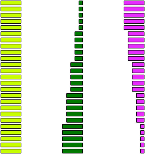
FIGURE 3. Structures of the solenoid magnets consisting of pancake windings with a rectangular cross-section, with a trapezoidal cross-section, and with an inverted trapezoidal cross-section.
Taking the solenoid with a trapezoidal cross-section as an example, the inner diameter, outer diameter and turns of the pancake coil located at the 1–5 steps are shown in Table 2. Since the stepped distribution of inverted trapezoidal is opposite to the trapezoidal, it won’t be repeated here. The above setting of the outer diameter and inner diameter ensures that the strip consumption and coil quantity of the three solenoids are equal.
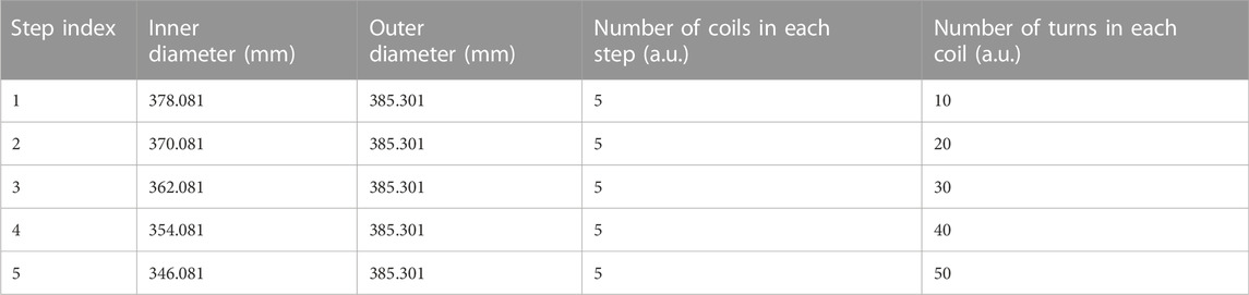
TABLE 2. Geometric parameters of the solenoid magnet with a trapezoidal section.
According to Eqs 7, 8 derived from the theoretical part (Section 2), the physical field was constructed by adding the PDE interface of the mathematics module of COMSOL Multiphysics. The generalized PDE has the following form:
In Eq. 9, the vector of dependent variables is denoted by u, ea is called the mass coefficient. da, Γ and f is known as the damping coefficient, the flux vector and the source term, respectively. By comparing with Eq. 8, the above terms in Eq. 9 can be determined as
In our case, the essence of simulation is to substitute Eqs 10–15 into Eq. 9 to solve Hr and Hz, and then further calculate the critical current Jc. Because of the insulating layer between the turns of the superconducting strip does not contain magnetic materials, so the relative permeability μr in Eq. 13 is set to 1. The resistivity of air is set to 1e6 Ω m, while resistivity of superconducting strip is calculated by combining Eqs 4, 5. Table 3 summarizes the electromagnetic parameters involved in the above calculation. The data are mainly from the product introduction and test report of Shanghai Superconductor Technology Co., LTD. Moreover, it is necessary to set reasonable boundary conditions and constraints so that the generalized PDE can obtain unique solutions. Assuming that the air domain is infinite, and there is no external background magnetic field in the environment where the solenoid magnet is located. At the boundary of the air domain, the magnetic field excited by the current passing through the solenoid will decay to 0. Accordingly, the Dirichlet boundary conditions set here is Hr = 0 and Hz = 0. The point constraint method must be used to constrain the current Iin flowing in the superconductor to ensure that the current is limited in the superconducting subdomain:
where s is the cross-section of the superconductor.

TABLE 3. Electromagnetic parameters involved in simulation.
It can be seen from Eq. 5 that the magnetic flux density perpendicular to the wide plane of the strip, that is, in the r direction of the axial coordinate system, is the main factor affecting the critical current density Jc. Figure 4 shows the magnetic flux density distribution parallel to the r direction when the current carried by the superconducting solenoid with rectangular cross-section is 100, 120, 140 and 160 A. The redder the colour is, the greater the magnetic flux density at this position is. From the simulation results, it can be clearly seen that the magnetic flux density is increasing with the increase of the input current, and its maximum value is generated in the coil at the top of the solenoid.
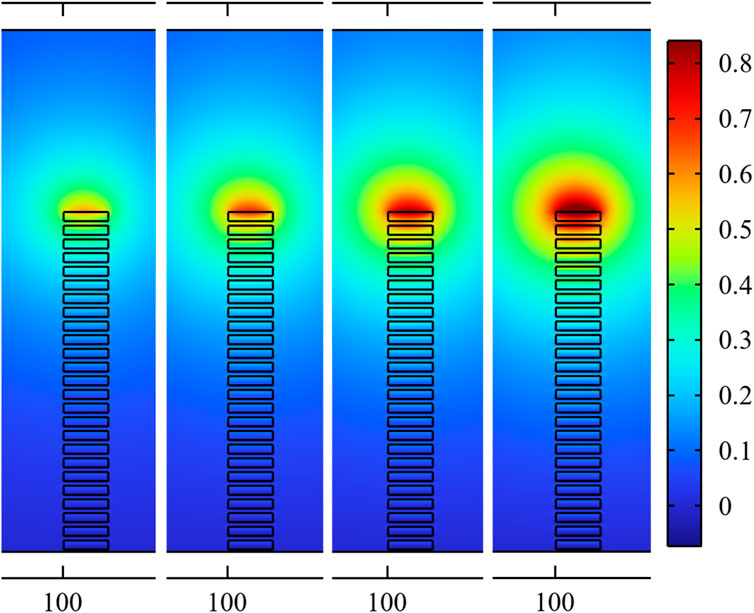
FIGURE 4. The magnetic flux density distribution in the r direction when the current carried by the superconducting solenoid is 100, 120, 140 and 160 A.
For understanding the magnetic flux density changing along the radial direction of the solenoid, the top coil was simulated as an example, and the magnetic flux density of each turn is given in Figure 5. It can be seen that no matter how much current is loaded, the maximum value of magnetic flux density in the r direction appears in the center of the pancake coil, while the minimum value appears at both ends. When the carrying current increases to 160 A, the magnetic flux density of the 25th turn in the r direction is the largest, which is 0.96 T.
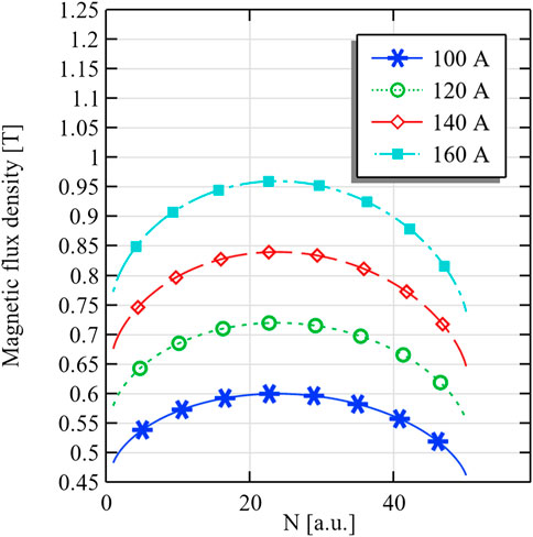
FIGURE 5. The magnetic flux density versus the turn of the pancake coil at the top.
Corresponding to different carried currents, the ratio of the current density J to its critical value Jc is given. As shown in Figure 6, the redder the color, the greater the ratio. The carried current is equal to the product of the current density and the cross-section of the strip. In the abstract coil model, the insulation layer, base material and superconducting layer are regarded as a bulk-like conductor, which is equivalent to enlarging the thickness of the superconducting layer of each turn of strip by 40 times. Under the same carried current conditions, the amplification of superconductor cross-section will lead to the reduction of the carried current density J, so it is necessary to multiply the simulated result by 40 for compensation. According to the color legend, when the current increases, J/Jc gradually decreases, indicating that the coil tends to lose its superconductivity, which is called “quench”. The “quench” of the upper coils is more obvious, indicating that the critical current density Jc here is smaller. By comparing the magnetic flux density distribution in Figure 4, it can be concluded that the difference of Jc of each pancake coil is mainly caused by the magnetic flux density change in the r direction. With the increase of the carried current, the influence of the magnetic flux density parallel to the wide plane of the superconducting strip on Jc is gradually revealed, which is shown by the continuous increase of Jc along the r direction. This change is not difficult to understand: the magnetic induction lines near the solenoid axis are relatively dense, so the magnetic flux density is large and the threshold current is small. Each turn of pancake coil constituting the solenoid is in the magnetic field generated by other turns, and its critical current Jc must be less than the given value of 160 A in Table 3. This explains why a small current of 100 A will also cause the coils at the top of the solenoid to “quench”, as shown in Figure 6.
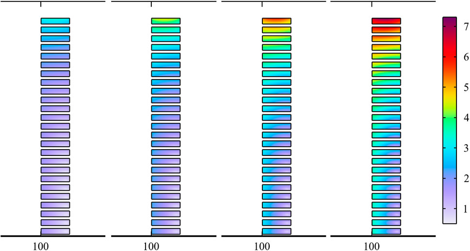
FIGURE 6. The J/Jc distribution of solenoid magnet with rectangular cross-section while the carried current is 100, 120, 140 and 160 A.
It can be seen from Figure 6 that the change of the critical current density of solenoid magnet in the axial and radial direction has certain rules, so the structure can be optimized by changing the distribution of coil spacing or turns. In case of the latter, the simulation of J/Jc is repeated for the solenoids whose cross-sections are trapezoidal and inverted trapezoidal. Figure 7 shows the J/Jc distribution of solenoid with trapezoidal cross-section. The style and range of the color legend used are the same as those in Figure 6, which makes the comparison more intuitive. The overall change trend is the same as that observed in Figure 6, that is, J/Jc increases with the increase of carried current. When the carried current is 100 A, the hue of J/Jc in is purple, and its value is less than 3. With the increase of the carried current, the hue of J/Jc gradually changes from purple to red. When the applied current reaches 160 A, inconspicuous orange areas appear in several coils on the upper part of the solenoid.
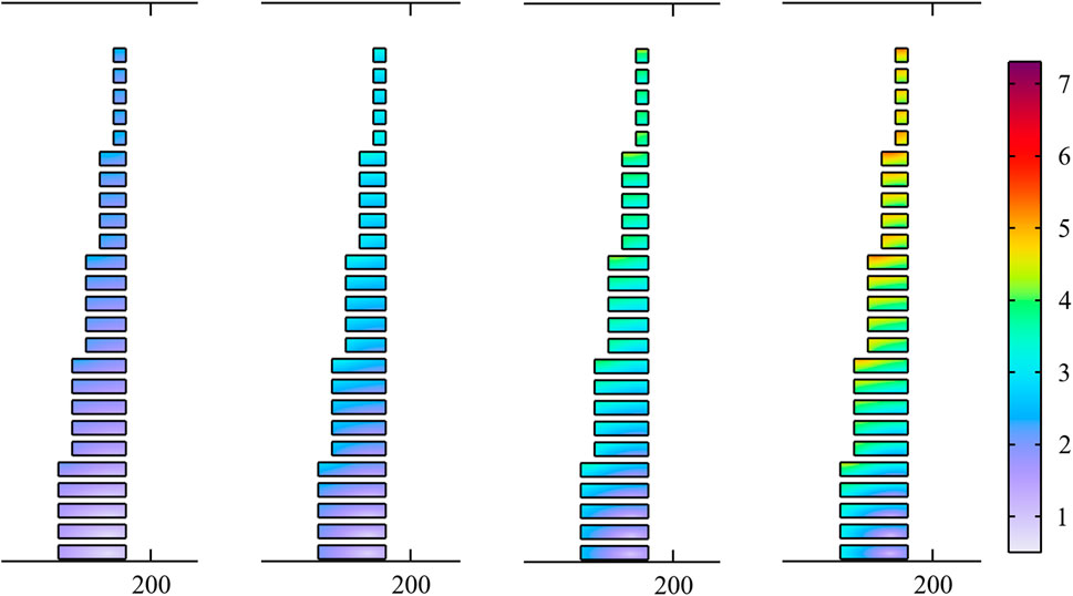
FIGURE 7. The J/Jc distribution of solenoid magnet with trapezoidal cross-section while the carried current is 100, 120, 140 and 160 A.
Figure 8 shows the J/Jc distribution of solenoid with inverted trapezoidal cross-section. The size of the coils included in this solenoid model has not changed, but their positions have been reversed. Compared with the simulation results of J/Jc given in Figures 6, 7, it is difficult to find any improvement. When the carried current is large, the critical current density at the top and inside of the solenoid still decreases significantly. In terms of size, solenoid magnets with rectangular, trapezoidal and inverted trapezoidal cross-sections have the same height, and their outer diameters are 239.22, 385.301 and 385.301 mm respectively. It is obvious that the inverted trapezoidal structure not only does not increase the critical current density, but also increases the volume of the solenoid. From these two aspects, solenoid with inverted trapezoidal cross-section is not desirable.
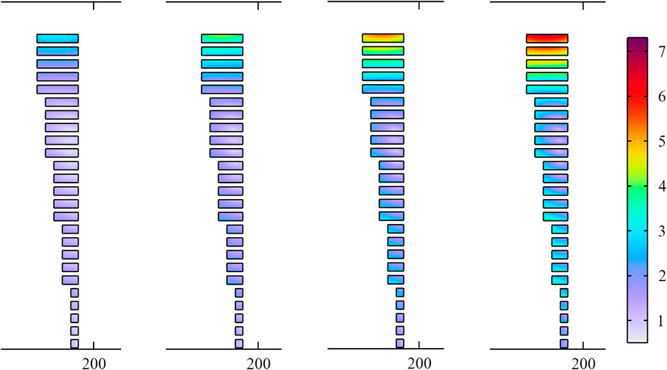
FIGURE 8. The J/Jc distribution of solenoid magnet with inverted trapezoidal cross-section while the carried current is 100, 120, 140 and 160 A.
Figures 6, 8 show that the critical current density at the center of the top of the solenoid is the smallest. Therefore, when the current is continuously increased, “quench” will occur here first. However, the previous simulation can only reflect the degree of “quench” of the three solenoid models at different positions, but cannot clearly give the specific critical current. To this end, the carried current is gradually increased from 50 to 100 A, and the J/Jc at the top center of the solenoid is shown in Figure 9. Under the same condition of J/Jc, the carried current I0 of the solenoid with inverted trapezoidal cross-section is slightly greater than that of the rectangular one, but significantly lower than that of the trapezoidal one. When the carried current density J is increased to be equal to the critical current density Jc, the horizontal axis coordinate of this position is the critical current I0. According to the original experimental data, the critical currents of solenoids with rectangular cross-section, trapezoidal cross-section and inverted trapezoidal cross-section are 46, 54 and 47.5 A respectively.
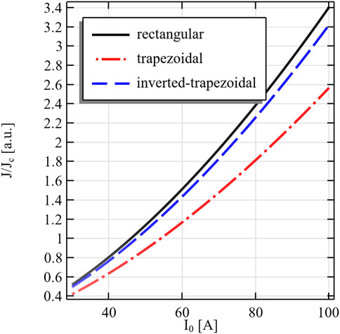
FIGURE 9. The changing of J/Jc while the carried current is increasing from 30 to 100 A.
The FEM-based modelling and simulation of HTS solenoid is reported in the paper. Through the PDE interface provided by COMSOL Multiphysics, the governing equation of electromagnetic field is set with the magnetic field strength H as the dependent variable. Superconducting strips, insulating layers and substrate materials are abstracted into a bulk-like conductor, which improves the quality of grids and the convergence speed of simulation. For solenoid magnets with rectangular, trapezoidal and inverted trapezoidal cross sections, the distributions of magnetic flux and current density are studied. Based on the experimental results, the following conclusions are drawn:
(1) Compared with the self-field critical current of the strip given in the datasheet, the value obtained by simulating the solenoid is smaller, because any turn of superconducting strip included in the model is also under the magnetic field of other turns.
(2) When the current applied on the solenoid continuously increases, the most obvious position of “quench” is the middle turn of the coil at the upper and lower ends, while the outer turn of the coil at the middle is the most safe and reliable.
(3) For the solenoid models with the same amount of superconducting consumables, the trapezoidal one can withstand the maximum current, while the inverted trapezoidal one is slightly better than the rectangular one.
(4) The current density distribution on the solenoid with trapezoidal cross-section is very uniform, which avoids deformation and even damage caused by local overheating.
Although the simulation fully proves the advantages of trapezoidal solenoid in critical current, it is not the only standard to evaluate the performance of superconducting magnets. The energy storage capacity, which is as important as the critical current, will be the focus of future research of us.
The raw data supporting the conclusion of this article will be made available by the authors, without undue reservation.
The authors contributed to the present study as follows: MC and XC: conceptualization; MC and KZ: methodology; MC, SZ, and KZ: validation; MC: formal analysis, writing—original draft preparation; KZ: investigation and writing—review and editing; SZ: resources, software, and visualization. All authors have read and agreed to the published version of the manuscript.
This paper is supported by the National Natural Science Foundation (China), grant number 61963031; the Basic Scientific Research Business Expense Project of Colleges and Universities Directly under Inner Mongolia Autonomous Region, grant number GXKY22045; Key Laboratory of Intelligent Manufacturing Technology; Intelligent Agricultural equipment and technical team of Inner Mongolia Minzu University.
We would also like to thank Lynn for language editing.
The authors declare that the research was conducted in the absence of any commercial or financial relationships that could be construed as a potential conflict of interest.
All claims expressed in this article are solely those of the authors and do not necessarily represent those of their affiliated organizations, or those of the publisher, the editors and the reviewers. Any product that may be evaluated in this article, or claim that may be made by its manufacturer, is not guaranteed or endorsed by the publisher.
1Shanghai Superconductor (2021). Second generation high temperature superconducting tape. http://www.shsctec.com/index.php?m=list&a=index&classid=25 [Accessed 15 October 2022]
Ainslie, M. D., Hu, D., Zermeno, V. M. R., and Grilli, F. (2017). Numerical simulation of the performance of high-temperature superconducting coils. J. Supercond. Nov. Magn. 30 (7), 1987–1992. doi:10.1007/s10948-016-3842-2
Arai, J., Higashikawa, K., Koshizuka, T., Ikeda, H., Harid, N., and Al-Durra, A. (2019). Feasibility study of superconducting cable application to oil/gas power supply network. IEEE Trans. Ind. Appl. 55 (1), 145–151. doi:10.1109/TIA.2018.2866466
Bednorz, J. G., and Müller, K. A. (1986). Possible high Tc superconductivity in the Ba-La-Cu-O system. Z. Phys. B -. Condens. Matter 64, 189–193. doi:10.1007/BF01303701
Berlincourt, T. G. (1987). Emergence of Nb-Ti as supermagnet material. Cryogenics 27 (6), 283–289. doi:10.1016/0011-2275(87)90057-9
Cavanagh, D. C., and Powell, B. J. (2018). Nuclear magnetic resonance in low-symmetry superconductors. Phys. Rev. B 97 (2), 024509024509–024509. doi:10.1103/physrevb.97.024509
Chen, L., Chen, H., Yang, J., He, H., Liu, X., Yu, Y., et al. (2018). Conceptual design and performance evaluation of a 35-kv/500-a flux-coupling-type sfcl for protection of a dfig-based wind farm. IEEE Trans. Appl. Supercond. 28 (3), 1–7. doi:10.1109/TASC.2017.2775566
Cummings, M. A., and Johnson, R. (2017). Superconducting rf linacs driving subcritical reactors for profitable disposition of surplus weapons-grade plutonium. Phys. Procedia 90, 170–179. doi:10.1016/j.phpro.2017.09.055
Dadras, S., Dehghani, S., Davoudiniya, M., and Falahati, S. (2017). Improving superconducting properties of YBCO high temperature superconductor by Graphene Oxide doping. Mater. Chem. Phys. 193, 496–500. doi:10.1016/j.matchemphys.2017.03.003
Du, Y., Zheng, J., Bao, Y., Chen, Y., Yang, X., Hu, Z., et al. (2020). Feasibility study of a dc linear motor based on the magnet track of high-temperature superconducting maglev. IEEE Trans. Appl. Supercond. 30 (3), 36006051–36006055. doi:10.1109/TASC.2019.2940178
Guo, P., Xie, J., Dong, X., and Huang, Y. (2019). A two-dimensional axisymmetric finite element analysis of coupled inertial-viscous-frictional-elastic transients in magnetorheological dampers using the compressible Herschel-Bulkley fluid model. Front. Mat. 6, 293. doi:10.3389/fmats.2019.00293
Indira, G., UmaMaheswaraRao, T., and Chandramohan, S. (2015). Enhancing the design of a superconducting coil for magnetic energy storage systems. Phys. C Supercond. its Appl. 508, 69–74. doi:10.1016/j.physc.2014.11.005
Jia, Y., Yuan, H., Wang, Z., Gao, P., Liu, S., Jiang, P., et al. (2019). Piecewise compensation and redundancy design for superconducting cavity failure of CiADS linac. Nucl. Phys. Rev. 36 (1), 62–70. doi:10.11804/NuclPhysRev.36.01.062
Kar, S., Kulkarni, S., Dixit, M., Singh, K. P., Gupta, A., Balasubramanyam, P. V., et al. (2012). Study on recovery performance of high Tc superconducting Tapes for resistive type superconducting fault current limiter applications. Phys. Procedia 36, 1231–1235. doi:10.1016/j.phpro.2012.06.281
Kim, Y., Hempstead, C. F., and Strnad, A. R. (1963). Magnetization and critical supercurrents. Phys. Rev. 129 (2), 528–535. doi:10.1103/PhysRev.129.528
Klyukhin, V., Curé, B., Amapane, N., Ball, A., Gaddi, A., Gerwig, H., et al. (2019). Using the standard linear ramps of the cms superconducting magnet for measuring the magnetic flux density in the steel flux return yoke. IEEE Trans. Magn. 55 (2), 1–48300504. doi:10.1109/tmag.2018.2868798
Kondoh, S., Ando, Y., Onoda, M., Sato, M., and Akimitsu, J. (1988). Superconductivity in Tl-Ba-Cu-O system. Solid State Commun. 65 (11), 1329–1331. doi:10.1016/0038-1098(88)90086-5
Kunzler, J. E., Buehler, E., Hsu, F. S. L., and Wernick, J. H. (1961). Superconductivity inNb3Sn at high current density in a magnetic field of 88 kgauss. Phys. Rev. Lett. 7 (5), 215. doi:10.1103/PhysRevLett.7.215
Maeda, H., Tanaka, Y., Fukutomi, M., and Asano, T. (1988). A new high-tc oxide superconductor without a rare Earth element. Jpn. J. Appl. Phys. 27 (2), L209–L210. doi:10.1143/JJAP.27.L209
Magnusson, N., Eliassen, J. C., Abrahamsen, A. B., Nysveen, A., Bjerkli, J., Runde, M., et al. (2015). Design aspects on winding of an mgb2 superconducting generator coil. Energy Procedia 80, 56–62. doi:10.1016/j.egypro.2015.11.406
Misko, V. R., and Nori, F. (2012). Magnetic flux pinning in superconductors with hyperbolic-tessellation arrays of pinning sites. Phys. Rev. B 85 (18), 184506. doi:10.1103/PhysRevB.85.184506
Mukherjee, P., and Rao, V. V. (2019). Design and development of high temperature superconducting magnetic energy storage for power applications - a review. Phys. C Supercond. its Appl. 563, 67–73. doi:10.1016/j.physc.2019.05.001
Onnes, H. K. (1991). “G. On the electrical resistance of pure metals, etc. VI. On the sudden change in the rate at which the resistance of mercury disappears,” in Further experiments with liquid HeliumThrough measurement to knowledge. Boston studies in the philosophy of science. Editors K. Gavroglu, and Y. Goudaroulis (Dordrecht: Springer), 267–272. doi:10.1007/978-94-009-2079-8_17
Peng, L., Xu, J., Cai, C., Zhu, Y., Zhou, L., and Zhang, Y. (2020). Dynamic properties of vortex states in mesoscopic superconducting strips with a temporally periodic pinning landscape. J. Low. Temp. Phys. 198 (1), 90–99. doi:10.1007/s10909-019-02246-y
Rajput, M., Swami, H. L., Kumar, R., Bano, A., Vala, S., Abhangi, M., et al. (2022). Deuterium ion irradiation impact on the current-carrying capacity of DI-BSCCO superconducting tape. Nucl. Eng. Technol. 54, 2586–2591. doi:10.1016/j.net.2022.02.008
Shaqsi, A. Z. A., Sopian, K., and Al-Hinai, A. (2020). Review of energy storage services, applications, limitations, and benefits. Energy Rep. 6 (7), 288–306. doi:10.1016/j.egyr.2020.07.028
Wang, X., Yang, J., Zhang, X., and Yu, X. (2015). An action dependent heuristic dynamic programming-controlled superconducting magnetic energy storage for transient stability augmentation. Phys. Procedia 65, 286–290. doi:10.1016/j.phpro.2015.05.153
Wu, M. K., Ashburn, J. R., Torng, C. J., Hor, P. H., Meng, R. L., Gao, L., et al. (1987). Superconductivity at 93 K in a new mixed-phase Y-Ba-Cu-O compound system at ambient pressure. Phys. Rev. Lett. 58, 908–910. doi:10.1103/PhysRevLett.58.908
Yang, S., Sun, J., Xu, L., Zhou, Q., Chen, X., Zhu, S., et al. (2020). Au@ ZnO functionalized three–dimensional macroporous WO3: A application of selective H2S gas sensor for exhaled breath biomarker detection. Sensors Actuators B Chem. 324, 128725. doi:10.1016/j.snb.2020.128725
Zhao, J., Liu, X., Qiu, W., Ma, Y., Huang, Y., Wang, J. X., et al. (2014). Surface-plasmon-polariton whispering-gallery mode analysis of the graphene monolayer coated InGaAs nanowire cavity. Opt. Express 22 (5), 5754–5761. doi:10.1364/OE.22.005754
Zhu, J., Chen, P., Zhang, H., Qiu, M., Zhang, H., Gong, J., et al. (2018). Design and characteristic study of a novel internal cooling high temperature superconducting composite cable with rebco for energy storage applications. IEEE Trans. Appl. Supercond. 28 (3), 14801305–5. doi:10.1109/tasc.2017.2782665
Keywords: superconducting, solenoid magnet, pancake coil, critical current, finite element method
Citation: Cong M, Zhang S, Chen X and Zhou K (2022) Finite element simulation and structure optimization of HTS solenoid. Front. Mater. 9:1109896. doi: 10.3389/fmats.2022.1109896
Received: 28 November 2022; Accepted: 06 December 2022;
Published: 15 December 2022.
Edited by:
Wei Wang, Beijing University of Chemical Technology, ChinaReviewed by:
Chen Chen, Jilin University, ChinaCopyright © 2022 Cong, Zhang, Chen and Zhou. This is an open-access article distributed under the terms of the Creative Commons Attribution License (CC BY). The use, distribution or reproduction in other forums is permitted, provided the original author(s) and the copyright owner(s) are credited and that the original publication in this journal is cited, in accordance with accepted academic practice. No use, distribution or reproduction is permitted which does not comply with these terms.
*Correspondence: Menglong Cong, Y29uZ21sQGltdW4uZWR1LmNu
Disclaimer: All claims expressed in this article are solely those of the authors and do not necessarily represent those of their affiliated organizations, or those of the publisher, the editors and the reviewers. Any product that may be evaluated in this article or claim that may be made by its manufacturer is not guaranteed or endorsed by the publisher.
Research integrity at Frontiers
Learn more about the work of our research integrity team to safeguard the quality of each article we publish.