 Shun Guo
 Xiaopeng Li
 Kewei Dong1,2
94% of researchers rate our articles as excellent or good
Learn more about the work of our research integrity team to safeguard the quality of each article we publish.
Find out more
ORIGINAL RESEARCH article
Front. Mater. , 30 November 2022
Sec. Structural Materials
Volume 9 - 2022 | https://doi.org/10.3389/fmats.2022.1098397
This article is part of the Research Topic Joining and Welding of New and Dissimilar Materials - Volume II View all 6 articles
High-quality joining of TiAl alloy to stainless steel is of great significance to the aerospace field. However, the hybrid structure of TiAl and 316L always suffers from insufficient strength when serving at elevated temperatures. In this work, a high-melting-point quaternary Ni-Nb-Zr-Ti amorphous alloy was applied as the filler metal to braze the two alloys at different temperatures. The microstructure and mechanical properties were studied in detail, and the results indicated that the joint was divided into three different regions and various reaction products were formed after brazing. The shear strength of the joint tends to first increase and then decrease with increasing brazing temperature. A satisfactory joint was obtained at 1090°C, and the highest shear strength reached 290 MPa and 180 MPa at room temperature and 750°C, respectively. Shear fracture indicates that there were obvious cleavage steps and some secondary cracks on the fracture surface, indicating that a high-melting-point quaternary Ni-Nb-Zr-Ti amorphous alloy is useful to improve the shear strength of TiAl alloy and 316L stainless steel, but it is difficult to effectively improve the plasticity. The fracture occurred on the TiAl interfacial region, and the phase causing microcrack initiation and propagation was AlNiTi.
With the development of aerospace, chemical energy and other industries, the range and speed of aircraft have gradually increased, and the service environment of various engineering components has become increasingly harsh, which puts forwards higher requirements for the mechanical and physical properties of engineering materials (Han et al., 2017; Yu et al., 2022). TiAl alloy is a new type of superalloy material with superior comprehensive properties, such as high specific strength, specific stiffness, creep resistance, oxidation resistance and low density, and is an ideal alloy in the aerospace field (Dong et al., 2019; Huang et al., 2021; Wang et al., 2021; Liu et al., 2022; Wang et al., 2022). Stainless steel has low cost, strong corrosion resistance, easy processing, etc. The hybrid structure of TiAl and 316L can give full play to their advantages in performance and economy, and among the many manufacturing methods, welding proves to be the most flexible and convenient method (Dong et al., 2021; Zhang et al., 2022a). However, due to the large difference in physical properties (including melting point, thermal expansion coefficient, thermal conductivity, etc.) and chemical properties (easy to form Ti-Fe/Ti-Al/Al-Fe brittle intermetallic compounds) between titanium and steel, it is difficult to obtain excellent joints by traditional arc welding (Muralimohan et al., 2014; Lim et al., 2021; Liu and Fujii, 2021).
Good welding process design is the basis for realizing high strength joint (Meng et al., 2021; Xie et al., 2022). The brazing method has proven to be the most suitable welding method for hard-to-weld dissimilar metal joining (Schwartz, 2003). When brazing, the whole workpiece is heated, so the deformation and residual stress are small. Moreover, the formation of brittle intermetallic compounds can be effectively inhibited by selecting an appropriate filler metal. Therefore, selecting an appropriate filler metal plays a dominant role in obtaining a satisfactory joint (Way et al., 2020; He et al., 2022). Considering the serving conditions of the two alloys, the selected filler metal should have good high-temperature properties. However, there are very few reports on this, and most of them use Ag-based or Ti-based solders to weld TiAl alloy and stainless steels. Laik et al. (2013) used Ag-based alloy solder to braze pure titanium and 304L stainless steel and found that there was a Ni-depleted solid solution layer and a discontinuous layer of (Ni,Fe)2TiAl formed on the stainless steel surface, but three contiguous layers of intermetallic compounds, CuTi, AgTi, and (Ag,Cu)Ti2, formed at the Ti-braze alloy interface, and failure in the joints occurred by the formation and propagation of cracks mostly along the Ti-braze alloy interface. To avoid the malignant effect of Ti-Cu compounds on the brazed joint, Lee et al. (2009) sputtered a layer of Ag metal on the titanium base metal in advance. A layer of Ti-Ag compound was produced in the brazed joint, which replaced the formation of brittle Cu-Ti series compounds. The tensile strength of the joint increased, and the tensile curve showed that the joint had a certain toughness. Noda et al. (1997) used Ti-15Cu-15Ni (wt.%) to braze TiAl alloy and AISI4340 structural steel. Since titanium is a strong carbide-forming element, a brittle TiC compound layer is formed on the steel side brazing seam, and the joint is stretched. After the tensile test, the TiC layer was fractured, and the tensile strengths were 220 MPa and 260 MPa at room temperature and 500°C, respectively. Although the application of Ti-based and Ag-based solders can achieve high-strength connections between TiAl alloys and steel, due to the relatively low melting points of Ti-based and Ag-based solders, the high-temperature strength of the obtained joints or the serviceable temperature are far from sufficient (Li et al., 2021).
Amorphous solder has attracted substantial attention for its special structure and concomitant excellent mechanical properties, which have been of special scientific and engineering value (Yang et al., 2021; Zhang et al., 2022b; Zhao et al., 2022). The thermodynamically nonsteady structure of amorphous solders is conducive to accelerating the diffusion of atoms and interfacial reactions during high-temperature brazing, reducing the temperature required for connection, thereby reducing the residual stress in the joint and improving the joint strength, but it is difficult to reduce the heat resistance temperature of the joint after brazing. To date, there are few reports on the application of high melting point amorphous alloys such as Ni-based amorphous alloys as interlayer brazing filler metals, and more are using Ti-based or Zr-based amorphous alloys with higher amorphous forming ability as brazing filler metals. Dong and Kong, (2019) reported that high-strength joining of TiAl- and Ni-based alloys was achieved by utilizing a multicomponent Zr-Al-Ni-Co amorphous filler metal. A low-melting-point Ti-based amorphous solder was also applied to join TiAl and Ni-based alloys (Liu and Fujii, 2021). Pang et al. (2016) reported that high-strength joining of titanium alloys, which is mainly attributed to the reduced amount of intermetallics in the braze zone, was achieved by using a TiZr-based amorphous solder.
In this work, a high-melting-point Ni-based amorphous ribbon with a nominal composition of Ni60Nb15Zr15Ti10 was fabricated by utilizing electron beam melting and single roll spin quenching technology and applied as the filler metal to braze TiAl alloy and 316L stainless steel. Since the melting point of the Nb element in the selected solder composition is as high as 2468°C, it is difficult to smelt the alloy evenly by the smelting method, such as arc melting, while the amorphous alloy is very sensitive to the composition; thus, electron beam melting is a good choice. The brazing was performed at different temperatures because the high brazing temperature has a large influence on the joint. The microstructure of the joint and the relationship between the microstructure and the mechanical properties were studied in detail.
The base metals used in this work are TiAl-4822 and 316L stainless steel, which chemical composition are shown in Table 1 and Table 2, respectively. Lamellar filler metal Ni60Nb15Zr15Ti10 with a thickness of 0.5 mm was fabricated by electron beam melting and single roll spin quenching technology. Commercial Nb, Mo, Ta, W and Zr elemental raw materials with purities higher than 99.95 wt% were first melted by electron beam melting technology into an alloyed ingot. Table 3 shows the melting parameters. Then, the obtained ingot was remelted in the quartz tube and injected into a high-speed rotating copper wheel to fabricate the ribbon-shaped filler metal. Bruker AXS D8 Advance X-ray diffraction (XRD) and differential scanning calorimetry (DSC) were used to determine the structure and thermal behaviors with a detection degree from 10° to 80° and a heating rate of 20 K/min, respectively. Figure 1 shows the XRD pattern and DSC curve of the obtained amorphous ribbon. From Figure 1A, it can be seen that only one broad peak exists in the pattern, indicating an amorphous structure of the obtained ribbon. From Figure 1B, the melting point of the ribbon was detected to be approximately 1331 K. According to the value, brazing parameters can be determined.
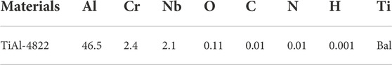
TABLE 1. Chemical compositions of TiAl-4822 and 316 stainless steel (wt.%).

TABLE 2. Chemical compositions of 316 stainless steel (wt.%).

TABLE 3. Parameters of the vacuum electron beam melting.
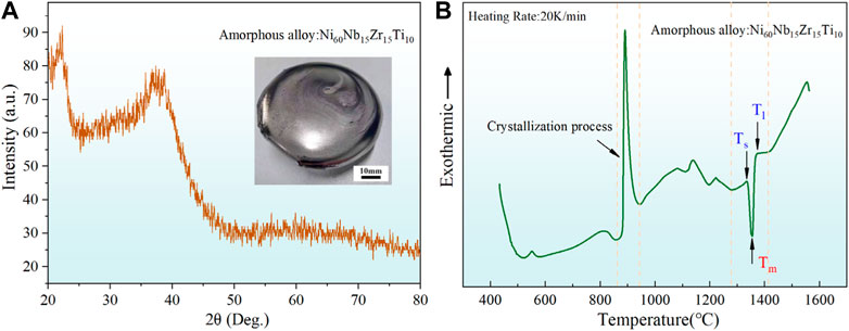
FIGURE 1. (A) XRD pattern and (B) DSC curve of the obtained amorphous ribbon.
Before brazing, the contacting surfaces of TiAl and 316L base metals were polished with SiC paper and cleaned using acetone to remove the oxide layer and oil contamination. The samples were assembled as shown in Figure 2A with the amorphous filler metal as the intermediate layer. Brazing was performed in a vacuum hot-pressing furnace with an atmosphere of 10–3 Pa and a pressure of 5 MPa. Figure 2B illustrates the heating process. According to the DSC results of the ribbon, the brazing temperatures were determined to be 1070°C, 1080°C, 1090°C and 1100°C, with the same holding time of 10 min.
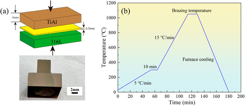
FIGURE 2. (A) Brazing assembly schematic and (B) heating process schematic.
After brazing, a Quant 250FEG scanning electron microscope (SEM) equipped with an EDS was applied to characterize the microstructure and elemental distribution of the joint. Bruker AXS D8 Advance XRD and FEI Tecnai 20 transmission electron microscope (TEM) equipped with a selected area electron diffraction (SAED) were used to identify the phases formed in the joint. Shearing tests with a loading rate of 0.15 mm/min were performed at room temperature and 750°C to study the shear strength of the joint at room temperature and elevated temperature.
Figure 3 shows the SEM microstructures of the joint brazed at 1070 °C, 1080 °C, 1090 °C and 1100 °C. From the pictures, it can be observed that after brazing, a sound joint was obtained. The interfaces between the base metals and filler metal are free from cracks and holes. In addition, it can be found that temperature has a great influence on the microstructure evolution of the joint. When the brazing temperature was low, i.e., 1070 °C, the metal of the intermediate layer was not completely melted, and the interface reaction was not sufficient, as shown in Figure 3A. As the brazing temperature increased to 1080°C, the filler metal melted completely, and after the brazing was cooled and solidified, based on the differences in morphology, it can be seen that the intermediate layer was mainly composed of dendritic phases and bulky phases.
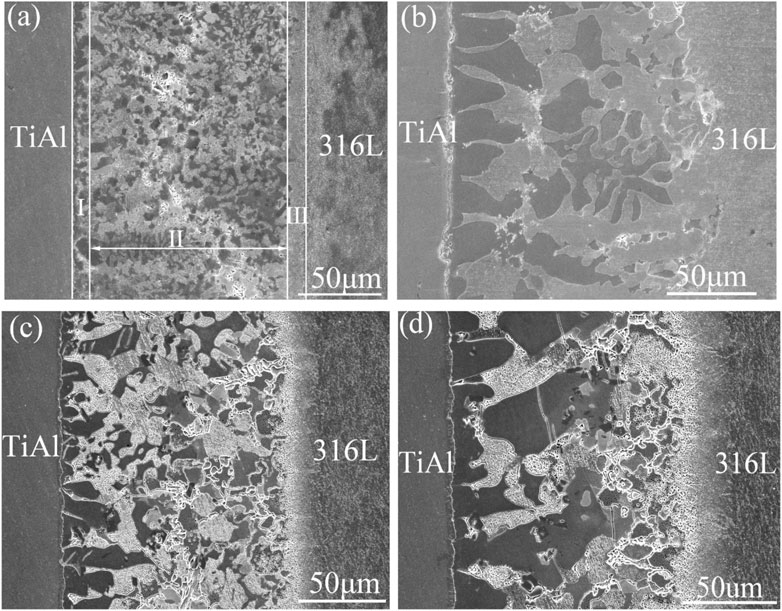
FIGURE 3. Scanning electron microscopy images of the joint bonded at (A) 1070°C, (B) 1080°C, (C) 1090°C and (D) 1100°C.
At the interface of 316L and filler metal, due to the good chemical solubility of the major elements of Fe in 316L and Ni in the filler metal, it was difficult to find a clear line after sufficient reaction, while a thin layer was formed at the interface of TiAl and filler metal. Continuing to increase the brazing temperature did not make much change in the microstructure of the intermediate layer, as shown in Figure 3C. However, when the brazing temperature rises to 1100°C, the microstructure morphologies change significantly, and the reaction products tend to grow and coarsen. Based on previous research results (Dong et al., 2019), the aggregation and growth of reaction products are unfavorable to the mechanical properties of joints.
Figure 4 shows the EDS maps of the joint brazed at 1090°C. It can be found that Fe and Ni, as the major elements in the 316L are mainly distributed in the 316L base material. The Fe and Ni elements were detected in the intermediate layer due to the thermal diffusion behavior in the brazing process. In addition, because the mass fraction of Ni in the amorphous alloy, i.e., the filler layer, reaches 60%, some Ni atoms even diffuse into the base material of TiAl. An enrichment of Ti and Al elements was displayed in the TiAl material, while Nb mainly accumulated on the trunk of the dendrite phases, and Zr was uniformly displayed in the intermediate layer. The results indicate that Nb may participate in the transformation process of the main phases of the intermediate layer, while Zr may form a solid solution or act as a dispersed precipitation phase. Cheng et al. (2021) carried out a study of the precipitation behavior of the δ phase (Ni3Nb) in a nickel-based superalloy and indicated that Nb atoms easily combine with Ni atoms to form new phases of δ that easily concentrate around grain boundaries and are randomly distributed within grains. The result of this paper is consistent with that of a previous study (Cheng et al., 2021).
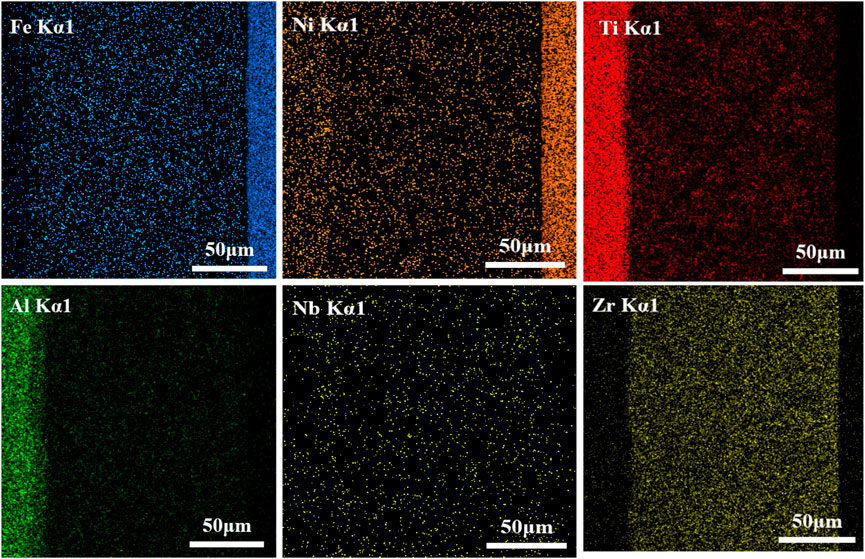
FIGURE 4. EDS map of the joint after brazing at 1090°C.
From Figure 3, it can be found that the joint was divided into three different regions: TiAl-based reaction layer (I), intermediate layer (II) and 316L-based reaction layer (III). To clarify the phase composition in different regions, XRD was performed, and the results are shown in Figure 5. The X-ray diffraction peaks of the 316L-based reaction layer corresponded to those of γ-Fe, indicating that the microstructure in the 316-based reaction layer was composed of the γ-Fe phase. The diffraction peaks of the intermediate layer are complex, and a variety of reaction products can be detected, including γ-(Fe, Ni), NiTiAl, NiTi2Al and Ni3(Ti, Al) et al. Because the intermediate layer is composed of a multielement alloy mainly composed of Ni element, atoms react with each other to form a variety of precipitates during rapid solidification. The diffraction peaks of the TiAl phase were found in the TiAl-based reaction layer, and some other phases were also found in the XRD pattern. The possible reason is that the effective diffusion of elements occurred in the TiAl-based reaction layer.
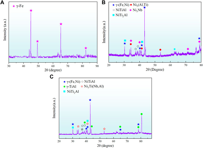
FIGURE 5. XRD pattern of (A) 316-based reaction layer, (B) intermediate layer and (C) TiAl-based reaction layer.
To study the phases within these regions in detail, high magnification of the three regions was characterized and analysed utilizing SEM and EDS, and the results are shown in Figure 6 and Figure 7, respectively. The EDS results indicate that the effective diffusion of elements occurs in the joint and that various phases may be formed in the reaction zone. Figure 6A shows the high magnification of the TiAl-based reaction layer. A thin off-white layer as well as some slightly irregular bulk phases were formed after brazing. According to the EDS and XRD results, the off-white layer phases marked with A were determined to be AlNiTi. The adjacent irregular block phases marked with B may be determined to be AlNi2Ti. Figure 6B and Figure 6C show the high magnification of the intermediate layer. The phases formed in this region were mainly derived from the solidification of residue filler metal. Depending on the morphology difference, the intermediate layer is mainly composed of two types of blocking: dendrite-like structures labelled with C and small ball-shaped phases marked with D, as well as a number of extremely fine phases marked with E. EDS and XRD results indicated that dendrite phase C was determined to be γ-(Fe,Ni) and D was a complex of Ni3 (Ti, Zr) and Ni3Nb phases. According to the Ti-Nb, Nb-Ni and Ti-Ni binary phase diagrams as well as the Ti-Nb-Ni ternary phase diagram, during solidification, this region first formed the supersaturated solid solution phases γ-Ni (Nb, Ti, Al), and as the temperature decreased, the solubility of supersaturated solid solutions decreased, precipitating Ni3(Ti, Nb) from the supersaturated solid solution phases (Zhang et al., 2022b). The phases within region E are relatively small and contain a variety of major elements, so it is difficult to determine its composition only by XRD and SEM. Figure 6D illustrates the morphology of the 316L-based reaction layer, and from the picture, it can be seen that after brazing, this region mainly includes two different phases marked with F and G. According to the EDS results of the F region and G region in Figure 7, it can be found that the blocky phase of F may be the γ′-Ni3(Ti,Nb) phase formed during solidification in the multicomponent alloy system, and the phase of the G region may be γ-(Fe,Ni), in which the content of Fe, Ni and Cr elements is similar to that in 316 L.
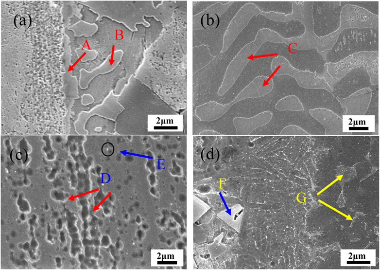
FIGURE 6. High magnifications of the (A) TiAl-based reaction layer, (B) and (C) intermediate layer and (D) 316L-based reaction layer.
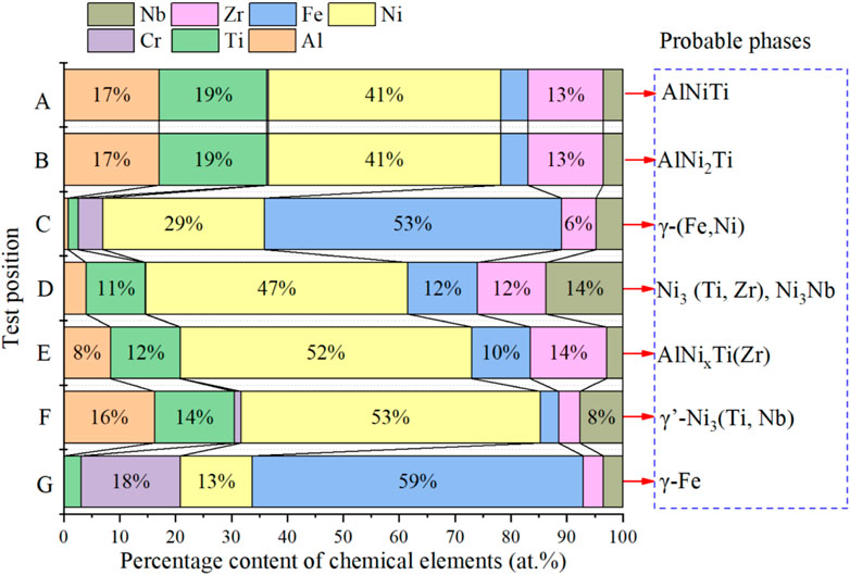
FIGURE 7. EDS results of the scanning zone marked in Figure 5 with arrows.
In order to further confirm the phases found in Figure 6C, TEM and selected area electron diffraction (SAED) were performed, and the results are shown in Figure 8. From the SAED pattern, in can be known that the TiAl phase shown in Figure 8A presented a lamellar structure, which SAED was marked in Figure 8D. From Figure 8B, it can be known that the fine phases with a size of approximately 200 nm were uniformly distributed in the matrix. Based on the SAED pattern shown in Figure 8E and Figure 8F, the phases of regions B and C were both the AlNi2Ti phase, and the phase of region D was determined to be the AlNiTi phase, which SAED was presented in Figure 8G. The TEM results verified the phase type inferred from the EDS analysis shown in Figure 7. In addition, a large number of nanosized precipitates were found in the reaction zone shown in Figure 8C, indicating that the multicomponent alloy system has a complex phase precipitation reaction, which may cause performance improvement.
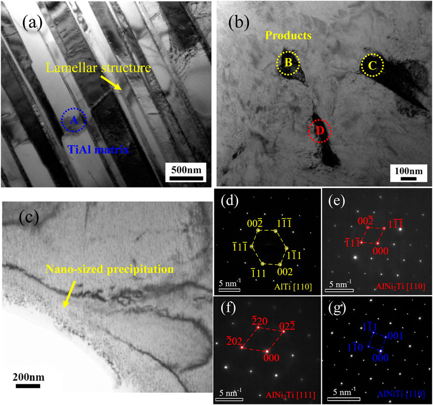
FIGURE 8. TEM image and corresponding SAED pattern: (A) TiAl matrix, (B) intermediate layer, (C) Nano-sized precipitation, (D) SAED pattern of region A marked in panel (A), (E–G) SAED pattern of region B, C and D marked in panel (B).
Figure 9 illustrates the phase formation process of the joint. It can be described as follows: in the initial stage (Figure 9A), the filler metal was completely melted. The Ni, Nb, Zr, and Ti elements in the filler metal started to diffuse into TiAl alloy and 316L stainless steel under the effect of concentration difference, while Ti and Al elements in the TiAl alloy and Fe, Cr, and Co elements in the 316L diffused into the filler metal. In the second stage (Figure 9B), as the amount of elemental diffusion increases in the interfacial regions, the elements react with each other, resulting in the formation of a number of bulky phases in the TiAl alloy interface. According to the Al-Ni-Ti ternary phase diagram, two different phases, AlNiTi and AlNi2Ti, are formed after the reaction. Without considering the influence of Al, NiTi will form first because NiTi possesses a low free energy (He et al., 1999):

FIGURE 9. Phase formation process of the joint: (A) initial stage of brazing, (B) formation of AlNiTi in the TiAl alloy interface, (C) formation of γ-(Fe, Ni) dendritic phase, (D) solidification stage of brazing.
However, due to the high content of Al in the reaction region, the above reaction is inhibited. Thus, in the second stage, the AlNiTi phase will be formed in the TiAl alloy interface. In the third stage, the continued diffusion of Ti and Al elements into the molten solder will cause the formation of:
As shown in Figure 9C. In addition, as the temperature decreased, γ-(Fe, Ni) dendritic phases started to form in the intermediate layer. Due to the good chemical compatibility between 316L and Ni-based filler metal, there is no clear line between filler metal and 316L and only some bulky γ-(Fe, Ni) phases finally formed in the 316L interfacial region, as shown in Figure 9D.
Considering the serving environment of the TiAl/316L joint, a shearing test was performed at room temperature and 750°C, and the results are shown in Figure 10. The results show that the joint brazed at 1090°C has the highest shear strength. The shear strength at room temperature and 750 °C reaches 290MPa and 180 MPa respectively, which are equivalent to 0.71 and 0.51 of that at room temperature and 750 °C of TiAl alloy. Dong et al. (2021) reported a TiAl alloy/316L stainless steel joint brazed with Zr-Cu-Ni-Al amorphous filler metal, and its maximum shear strength of brazed joints reached 129 MPa when brazed at 1020°C for 10 min. Compared with the results of this study, the filler metal of the Ni-Nb-Zr-Ti amorphous ribbon used could further improve the mechanical properties of TiAl alloy/stainless steel.
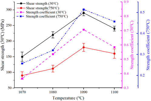
FIGURE 10. Shear strength of the joint tested at room temperature and 750°C.
In addition, Figure 10 shows that the variation in the average shear strength with temperature at room temperature and high temperature shows similar trends, namely, with increasing brazing temperature, the shear strength of joints at room temperature and high temperature both showed a trend of increasing first and then decreasing. This is mainly because when the brazing temperature is 1070°C, the joint reaction is not sufficient due to the high melting point of the brazing filler metal. With increasing brazing temperature, the atoms in the joint are fully diffused and reacted, and the joint strength is improved. However, when the temperature is too high, the tissue in the joint coarsens, which affects the performance of the joint. Figure 10 shows that the shear strength of the joint at room temperature and 750 °C was 240 MPa and 161 MPa, respectively, when the brazing temperature was increased to 1100 °C.
Figure 11 shows the fracture morphologies of the joint brazed at 1090°C tested at room temperature and 750°C. The high-density short and curved cleavage steps could be found from the figure of both fracture surfaces, which is characteristic of quasi-cleavage fracture. In addition, there is also a small fracture around the cleavage steps, the fracture surface is perpendicular to the shear stress, the fracture is flush and bright, and secondary cracks can be found, which indicates the high brittleness of the joint. Compared with the room temperature fracture, there are some obvious large-scale cleavage steps on the fracture surface of the high-temperature joint shown in Figure 11B. The crack propagation was in the form of a river pattern, and there were also obvious secondary cracks. According to the EDS result, the fracture occurred on the TiAl interfacial region, and the phase causing microcrack initiation and propagation may be AlNiTi. The shear test results show that it is difficult to connect dissimilar metals of TiAl alloy and 316L stainless steel. High-melting-point quaternary Ni-Nb-Zr-Ti amorphous alloy is useful to improve the shear strength of TiAl alloy and 316L stainless steel, but it is difficult to effectively improve the plasticity.
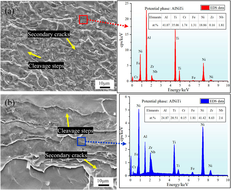
FIGURE 11. Fracture morphologies of the joint brazed at 1090°C tested at (A) room temperature and (B) 750°C.
A Ni60Nb15Zr15Ti10 high-temperature amorphous alloy has been successfully applied to dissimilar metals welding of TiAl alloy and 316L stainless steel. The hybrid structure of TiAl and 316L revealed high shear strength both at room temperature and 750°C. Some main conclusions were as follows:
1) Metallurgical bonding was realized through high temperature brazing. Due to good chemical compatibility between 316L SS and Ni-based amorphous solder, it is difficult to find a clear interface between them while a thin AlNiTi layer was formed on the TiAl alloy interface.
2) A satisfactory joint with high shear strength was obtained at 1090°C, and the highest shear strength reached 290 MPa and 180 MPa at room temperature and 750°C, respectively, proving that the high-temperature performance of the joint can be improved by utilizing a Ni60Nb15Zr15Ti10 filler alloy. The shear strength of the joint tend to increase and then decrease with increasing brazing temperature.
3) Both fractures of the joint tested at room temperature and 750°C were brittle. There were obvious cleavage steps and some secondary cracks on the facture surface, indicating that a Ni60Nb15Zr15Ti10 filler alloy is useful to improve the shear strength, but it is difficult to effectively improve the plasticity.
4) The fracture occurred on the TiAl interfacial region, and the phase causing microcrack initiation and propagation may be AlNiTi.
The original contributions presented in the study are included in the article/Supplementary Material, further inquiries can be directed to the corresponding author.
SG: conceptualization, methodology, investigation, and writing-original draft; XL: writing and editing; KD: resources and methodology. JG: conceptualization, investigation. QZ and KW: validation, resources. All authors listed have made a substantial, direct, and intellectual contribution to the work and approved it for publication.
This work is supported by the National Natural Science Foundations of China [Grant No. 52105367].
The authors declare that the research was conducted in the absence of any commercial or financial relationships that could be construed as a potential conflict of interest.
All claims expressed in this article are solely those of the authors and do not necessarily represent those of their affiliated organizations, or those of the publisher, the editors and the reviewers. Any product that may be evaluated in this article, or claim that may be made by its manufacturer, is not guaranteed or endorsed by the publisher.
Cheng, H., Lin, Y., He, D.-G., Qiu, Y.-L., Zhu, J.-C., and Chen, M.-S. (2021). Influences of stress-aging on the precipitation behavior of δ phase (Ni3Nb) in a nickel-based superalloy. Mater. Des. 197, 109256. doi:10.1016/j.matdes.2020.109256
Dong, H.-g., Zhang, R.-z., Xia, Y.-q., Hao, X.-h., and Peng, L. (2021). Interfacial features of TiAl alloy/316L stainless steel joint brazed with Zr− Cu− Ni− Al amorphous filler metal. Trans. Nonferrous Metals Soc. China 31 (6), 1680–1688. doi:10.1016/s1003-6326(21)65607-8
Dong, K., and Kong, J. (2019). A high-strength vacuum-brazed TiAl/Ni joint at room temperature and high temperature with an amorphous foil Zr-Al-Ni-Co filler metal. J. Manuf. Process. 44, 389–396. doi:10.1016/j.jmapro.2019.05.024
Dong, K., Kong, J., Yang, Y., Wang, H., Peng, Y., Zhou, Q., et al. (2019). Vacuum brazing of TiAl-based alloy and GH536 superalloy with a low-melting point amorphous Ti35Zr25Be30Co10 filler. J. Manuf. Process. 47, 410–418. doi:10.1016/j.jmapro.2019.07.042
Han, K., Wang, H., Zhang, B., Li, Y., and Wang, T. (2017). Effect of thermal compensation on microstructure and mechanical properties of electron-beam welded joint for high-Nb containing TiAl/Ti600 alloys. Mater. Des. 131, 273–285. doi:10.1016/j.matdes.2017.05.092
He, H., Zhang, Y., Niu, C., Zhao, Y., Ren, H., Liu, M., et al. (2022). Bonding performance of Ag–Cu brazing solders and half-heusler alloys for high-performance thermoelectric generators. ACS Appl. Mat. Interfaces 14 (36), 41588–41597. doi:10.1021/acsami.2c10991
He, P., Zhang, J., Zhou, R., and Li, X. (1999). Diffusion bonding technology of a titanium alloy to a stainless steel web with an Ni interlayer. Mater. Charact. 43 (5), 287–292. doi:10.1016/s1044-5803(99)00008-x
Huang, D., Tan, Q., Zhou, Y., Yin, Y., Wang, F., Wu, T., et al. (2021). The significant impact of grain refiner on γ-TiAl intermetallic fabricated by laser-based additive manufacturing. Addit. Manuf. 46, 102172. doi:10.1016/j.addma.2021.102172
Laik, A., Shirzadi, A., Tewari, R., Kumar, A., Jayakumar, T., and Dey, G. (2013). Microstructure and interfacial reactions during active metal brazing of stainless steel to titanium. Metall. Mat. Trans. A 44 (5), 2212–2225. doi:10.1007/s11661-012-1599-1
Lee, J. G., Hong, S., Lee, M., and Rhee, C. (2009). High strength bonding of titanium to stainless steel using an Ag interlayer. J. Nucl. Mater. 395 (1-3), 145–149. doi:10.1016/j.jnucmat.2009.10.045
Li, S., Liu, Z., Xia, Y., Wang, X., He, P., Jiu, Y., et al. (2021). Vacuum brazing TiAl intermetallics to GH3030 alloy with a multi-component Ti-based filler metal. J. Manuf. Process. 70, 484–493. doi:10.1016/j.jmapro.2021.09.001
Lim, Y., Morisada, Y., Liu, H., and Fujii, H. (2021). Ti-6Al-4V/SUS316L dissimilar joints with ultrahigh joint efficiency fabricated by a novel pressure-controlled joule heat forge welding method. J. Mater. Process. Technol. 298, 117283. doi:10.1016/j.jmatprotec.2021.117283
Liu, C., Wang, Y., Han, W., Ma, T., Ma, D., and Zhang, Y. (2022). Achieving superior high-temperature strength and oxidation resistance of TiAl nanocomposite through in situ semicoherent MAX phase precipitation. ACS Appl. Mat. Interfaces 14 (6), 8394–8403. doi:10.1021/acsami.1c21719
Liu, H., and Fujii, H. (2021). Ultralow rotation speed produces high-quality joint in dissimilar friction welding of Ti–6Al–4V alloy and SUS316L stainless steel. Mater. Sci. Eng. A 800, 140303. doi:10.1016/j.msea.2020.140303
Meng, X., Huang, Y., Cao, J., Shen, J., and dos Santos, J. F. (2021). Recent progress on control strategies for inherent issues in friction stir welding. Prog. Mater. Sci. 115, 100706. doi:10.1016/j.pmatsci.2020.100706
Muralimohan, C., Muthupandi, V., and Sivaprasad, K. (2014). Properties of friction welding titanium-stainless steel joints with a nickel interlayer. Procedia Mater. Sci. 5, 1120–1129. doi:10.1016/j.mspro.2014.07.406
Noda, T., Shimizu, T., Okabe, M., and Iikubo, T. (1997). Joining of TiAl and steels by induction brazing. Mater. Sci. Eng. A 239, 613–618. doi:10.1016/s0921-5093(97)00638-2
Pang, S., Sun, L., Xiong, H., Chen, C., Liu, Y., Li, H., et al. (2016). A multicomponent TiZr-based amorphous brazing filler metal for high-strength joining of titanium alloy. Scr. Mater. 117, 55–59. doi:10.1016/j.scriptamat.2016.02.006
Wang, L., Zhang, Y., Hua, X., Shen, C., Li, F., Huang, Y., et al. (2021). Twin-wire plasma arc additive manufacturing of the Ti–45Al titanium aluminide: Processing, microstructures and mechanical properties. Intermetallics 136, 107277. doi:10.1016/j.intermet.2021.107277
Wang, L., Zhou, W., Shen, C., Zhang, Y., Li, F., Ding, Y., et al. (2022). Effect of substrate temperature on microstructure and mechanical properties of TiAl alloy fabricated using the twin-wire plasma arc additive manufacturing system. J. Mat. Sci. 57 (19), 8940–8955. doi:10.1007/s10853-022-07228-2
Way, M., Willingham, J., and Goodall, R. (2020). Brazing filler metals. Int. Mater. Rev. 65 (5), 257–285. doi:10.1080/09506608.2019.1613311
Xie, Y., Meng, X., Chang, Y., Mao, D., Yang, Y., Xu, Y., et al. (2022). Ameliorating strength-ductility efficiency of graphene nanoplatelet-reinforced aluminum composites via deformation-driven metallurgy. Compos. Sci. Technol. 219, 109225. doi:10.1016/j.compscitech.2021.109225
Yang, T., Zhang, Y., Wang, K., Zhang, D., Chen, F., and Guo, C. (2021). Interface behaviour of brazing seam of contact-reaction brazing an AZ31 magnesium with amorphous filler metal. J. Manuf. Process. 68, 683–689. doi:10.1016/j.jmapro.2021.05.061
Yu, T., Wang, H., Han, K., and Zhang, B. (2022). Microstructure and wear behavior of AlCrTiNbMo high-entropy alloy coating prepared by electron beam cladding on Ti600 substrate. Vacuum 199, 110928. doi:10.1016/j.vacuum.2022.110928
Zhang, G., Chen, G., Ma, Y., Zhang, B., Cao, J., Dong, Z., et al. (2022a). A novel zipper shape joint for improving microstructure and mechanical property of electron beam welded TiAl joint. J. Manuf. Process. 81, 115–126. doi:10.1016/j.jmapro.2022.06.032
Zhang, G., Chen, H., Luo, Q., Yuan, Y., Liu, H., and Li, Q. (2022b). The design of Ti–Cu–Ni–Zr titanium alloy solder: Thermodynamic calculation and experimental validation. J. Mat. Sci. 57 (12), 6819–6831. doi:10.1007/s10853-022-07063-5
Keywords: TiAl alloy, 316L stainless steel, amorphous filler, high-temperature brazing, shear strength
Citation: Guo S, Li X, Dong K, Gu J, Zhou Q and Wang K (2022) Microstructure and shear property of high-temperature brazing of TiAl alloy and 316L stainless steel with a Ni-based amorphous filler. Front. Mater. 9:1098397. doi: 10.3389/fmats.2022.1098397
Received: 14 November 2022; Accepted: 21 November 2022;
Published: 30 November 2022.
Edited by:
Xiangchen Meng, Harbin Institute of Technology, ChinaReviewed by:
Shaojie Wu, Tianjin University, ChinaCopyright © 2022 Guo, Li, Dong, Gu, Zhou and Wang. This is an open-access article distributed under the terms of the Creative Commons Attribution License (CC BY). The use, distribution or reproduction in other forums is permitted, provided the original author(s) and the copyright owner(s) are credited and that the original publication in this journal is cited, in accordance with accepted academic practice. No use, distribution or reproduction is permitted which does not comply with these terms.
*Correspondence: Xiaopeng Li, bHhwQG5qdXN0LmVkdS5jbg==
Disclaimer: All claims expressed in this article are solely those of the authors and do not necessarily represent those of their affiliated organizations, or those of the publisher, the editors and the reviewers. Any product that may be evaluated in this article or claim that may be made by its manufacturer is not guaranteed or endorsed by the publisher.
Research integrity at Frontiers
Learn more about the work of our research integrity team to safeguard the quality of each article we publish.