 Jian-Hong Jiang1,2
 Xi-Long Huang
95% of researchers rate our articles as excellent or good
Learn more about the work of our research integrity team to safeguard the quality of each article we publish.
Find out more
ORIGINAL RESEARCH article
Front. Mater. , 28 November 2022
Sec. Structural Materials
Volume 9 - 2022 | https://doi.org/10.3389/fmats.2022.1082292
This article is part of the Research Topic Physico-Mechanical Properties and Treatment Technology of Hazardous Geomaterials View all 23 articles
Piles were regarded as elastic materials in the traditional numerical simulation. The elastic pile would not reflect the damage of the pile in engineering, which would misjudge the reinforcement effect of piles on slopes. The specific objective of this study was to propose a damage constitutive model to replace the traditional elastic constitutive model in the numerical analysis of pile–slope stability. In this study, the pile was simulated by a damage constitutive model, which can reflect the plastic deformation of the pile. The factors of pile position and reinforcement ratio on a slope’s factor of safety (FOS) are investigated by the finite difference method using FLAC3D. The lateral displacement, bending moment, shear force, and soil pressure of balance-reinforced piles are used to study the difference between damage and elastic constitutive models. The results showed that the FOS considering the damage constitutive model could be smaller, approximately 15% less than that considering an elastic constitutive model under specific conditions. Furthermore, the difference between the two evaluation results of the internal force of the same pile can reach about 30%. It was observed that the elastic constitutive model would overestimate the reinforcement effect of the pile on the slope, which will cause potential safety hazards in engineering. This study provides a realistic damage constitutive model for the design and evaluation of slope-stabilizing piles.
There are a large number of natural slopes due to the complex geographic and geomorphic conditions in China. Furthermore, many engineering slopes are caused by mining, highway, metro, railway, and hydropower projects in China (Chen et al., 2016). The landslide disaster on unstable slopes is one of the greatest challenges in geotechnical engineering (Bai et al., 2022). A considerable amount of technology has been established for slope reinforcement (Bai et al., 2021). Sun et al. (2010) indicated that the drainage tunnels significantly contribute to landslide control due to the dropping of the underground water level. Extensive research has shown that the natural slope stability can be notably increased by various reinforcement technologies, including anchored piles, cantilever piles, pre-stressed anchor cables, rock bolts, pre-consolidation grouting, and bottom drainage holes (Rahardjo et al., 2003; Jiang et al., 2015; Bai et al., 2019; Yan et al., 2019; Zheng et al., 2019; Chen et al., 2021; Xu and Xuang, 2021). For the past 30 years, we have seen increasingly rapid advances in the pile-reinforced slope. Researchers regarded pile reinforcement as a vital technology for slope stabilization, such as the advantage of lower cost, limited land occupation, and strong adaptability in engineering (Lin et al., 2018; Qu et al., 2018; Huang et al., 2020).
Recent trends in mathematics and computer science have led to a proliferation of studies about the numerical assessment of the stability of pile-reinforced slopes. Most researchers investigated the interaction of pile–soil under the lateral load based on finite element analysis software, such as FLEX 3D (Martin and Chen, 2005), ABAQUS (Gu et al., 2014), and ANSYS (Bakri et al., 2014). Cai and Ugai (2000) used the three-dimensional elastoplastic shear strength reduction finite element method to demonstrate that the pile should be installed in the middle of the slope. One study by Jeong et al. (2003) illustrated that the evaluation of pile-reinforced slopes is more conservative by uncoupled analysis than coupled analysis. Cheng and Jeremic (2009) presented a fully coupled soil–water dynamic finite element formulation to simulate the response of piles in liquefiable soil. The seismic displacement of the pile-reinforced slope was investigated by a three-dimensional limit analysis (He et al., 2015a). The pile-stabilized slopes under surface loading were analyzed comprehensively by finite difference analyses (Sharafi and Sojoodi, 2016). Many recent studies have established that numerical simulation could replace experiments to provide an accurate solution (Henke, 2010; He et al., 2015b; Jamsawang et al., 2015).
The failure mechanism of the pile with lateral load is complicated due to the interaction of many factors. Various studies have assessed the influence of soil stiffness, pile material, pile diameter, pile position, pile spacing, loading type, and slope gradient on slope stability (Won et al., 2005; Ashour and Ardalan, 2012; He et al., 2015c; Kavitha et al., 2016). It is essential to predict an accurate interaction behavior between piles and soil, and the safety factor of pile-reinforced slopes. Recently, two failure mechanisms of the laterally loaded pile have been mentioned. The pile was regarded as elastic or rigid material at the first failure mechanism. At this assumption, a sufficiently large anti-sliding force can be generated without causing pile failure. Moreover, the behavior of soil failure could be simulated by flow and short-pile modes (Poulos, 1995). The pile failure was considered to be another failure mechanism. When the maximum tensile stress of the pile reaches its ultimate strength, the plastic deformation and cracking of the pile will lead to the loss of slope stability. The existence of pile failure cannot be ignored in pile-reinforced slope engineering. However, to simplify the calculation, many recent researchers regarded piles as elastic solids when the stability of a pile–slope was analyzed by numerical simulation (Won et al., 2005; Hassen et al., 2009; Lin et al., 2018). The elastic pile, without considering the failure, would overestimate the slope instability. Furthermore, the elastic constitutive model did not accurately indicate the effect of piles with different reinforcement rates on slope stability. Piles with different reinforcement rates were modeled as elastic piles with different stiffnesses in the simulation. However, the stiffness of the piles made a small contribution to the stability of the slope (Lee et al., 1995). The tensile strength is significantly varied with the reinforcement ratio. Therefore, it is more realistic and accurate to use a constitutive model that can reflect the tensile strength and failure of the pile to estimate the slope reinforced with the pile.
In recent years, there has been an increasing interest in the numerical simulation of pile damage. Comodromos et al. (2009) presented a three-dimensional nonlinear analysis to estimate the cracking influences of concrete on the response of piles under lateral loading. The study by Larsson et al. (2012) demonstrated that a concrete damage plasticity model made it possible to simulate the fracture development of laterally loaded lime–cement columns. Yapage et al. (2015) offered a constitutive model affiliating a strain-softening behavior to explain the time-dependent failure of deep cement mixed columns reinforced embankment. Zheng et al. (2019) proposed a damage plasticity model to describe the strain-softening behavior of concrete piles, which has verified that a damage plasticity model closely matched the experimental results in the three-point bending test (Figure 1). Furthermore, Dai et al. (2022) developed an advanced damaged plasticity model to simulate the bending moment degradation of slope-stabilizing piles due to concrete cracking and crushing.
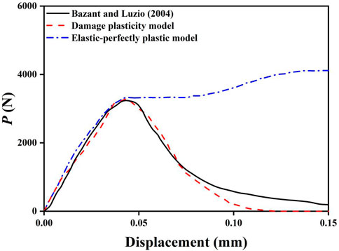
FIGURE 1. Load (P)–displacement curve from Zheng et al. (2018).
The main aim of this study is to establish a new approach to pile–slope stability analysis considering the damage constitutive model. Figure 2 illustrates the schemata of the slope stability analysis in the current study. A finite different method, in which the FOS of a pile-reinforced slope is calculated, was performed by FLAC3D software. The pile was simulated by the elastic constitutive model and the damage constitutive model. The influences of pile position and reinforcement ratio on the slope’s safety factor were explicitly investigated in this study. Additionally, the responses of the balance-reinforced pile were predicted by various constitutive models. All results obtained from the damage constitutive model were compared with that calculated by the elastic constitutive model in this study. The current study introduced a damage constitutive model instead of a traditional elastic model in the stability analysis of pile-reinforced slope. In this study, the responses of piles due to the lateral soil movement can provide a new reference for the design and implementation of reinforcing piles to increase slope stability.
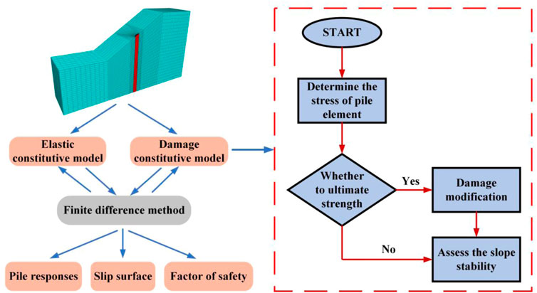
FIGURE 2. Schematic illustration of slope stability analysis.
The damage constitutive model can reflect the fracturing and crushing of piles during horizontal loading, which is unavailable for the traditional elastic model. The reinforcement ratios of piles are represented by different tensile strengths. A reinforced concrete pile undergoes irreversible cracking when it reaches a critical state. The damage constitutive model simulates the destruction of piles in the reduction of tensile strength and shear strength. To simulate the cracking performance, both the tensile strength and the elastic modulus perpendicular to the crack are set to zero when the tensile stress of a zone exceeds the tensile strength of the concrete (Cedolin et al., 1982; Comodromos et al., 2009).
Furthermore, the shear strength of piles will be reduced due to the shear stress redistribution on cracks. The concrete interface crossed by a reinforcing bar in the pile will be subjected to a shear displacement when the landslide happens. A local increase in the crack width will occur due to the deformation of protruding asperities in the shear displacement (Maekawa and Qureshi, 1997). The lateral dilatancy leads to a pullout force that responded by reinforcing bars, which is balanced with the compressive force acting on the concrete near the bar (Murcia-Delso and Benson Shing, 2016). Based on the aforementioned phenomenon, Tassios and Vintzeleou (1987) have proposed a phenomenological model to describe the relationship between normal compressive stresses with steel stress:
where σc is the normal compressive stress acting on the interface, σs is the steel stress, and ρ is the reinforcement percentage.
Significant dilatancies are expected when cracks through reinforced piles occur due to the interlocking of the protruding aggregates (Millard and Johnson, 1984). The considerable dilatancy causes high tensile stresses in the bars. It is precisely due to this dilatancy performance that a frictional resistance from the reinforcing bar is an evident part of the total shear resistance on the cracking interface (Harries et al., 2012). To obtain the shear strength in the reinforced pile, a model established by Tassios and Vintzeleou (1987) is applied.
where τfr,max is the maximum shear stress due to friction, μ is the friction coefficient, and σc,max is the maximum normal compressive stress acting on the interface. The τfr,max is regarded as the shear strength in the numerical analysis. The above damage constitutive model was coded into FLAC3D by the FISH programming language.
Figure 3 indicates a three-dimensional finite difference computational model of pile-reinforced slopes. An idealized slope with a height (H) of 10 m and a length (L) of 15 m is simulated with the software FLAC3D. The bedrock is 15 m below the ground surface as a rigid base. A damage constitutive simulation models a pile with a diameter of 1 m. Lx is the horizontal distance from the slope toe to the pile. Hence, the ratio between Lx and L (Lx/L) can be represented by the installation location of the pile. Interface elements in FLAC3D are applied to assume the interface between the pile and the soil, and the stiffness (kn) can be determined as follows (Itasca, 2006):
where K is the bulk moduli, G is the shear moduli, and the ΔZmin is the minimum width of an adjacent zone in the normal direction. In the current study, the mechanical parameters were obtained from Cai and Ugai (2000). The mechanical parameters of the soil and the pile are summarized in Table 1.
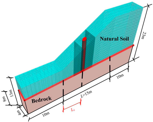
FIGURE 3. Schematic illustration of a homogeneous soil slope.
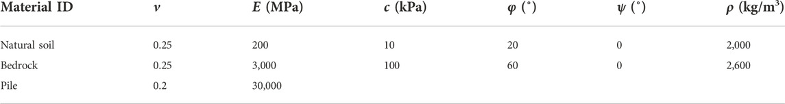
TABLE 1. Mechanical parameters of soil and pile.
Figure 4 indicates that the FOS of the pile-reinforced slope varied along the location of the pile. Three pile models are applied in the simulations, namely, the elastic constitutive model (ECM), damage constitutive model considering a balanced-reinforced (DCM-B) pile, and under-reinforced (DCM-U) pile, respectively. Moreover, the results calculated by a finite element method under the same parameters are plotted in Figure 4, where the piles are treated as linear elastic solid material (Cai and Ugai, 2000). A comparison of the findings with those of Cai and Ugai (2000) shows that they are similar, which confirms that the damage constitutive model is valid. It can be observed that the FOSs are in a parabolic shape along the Lx/L, and the most forceful pile location is in the middle of the slope. Compared to the FOS of the ECM, the FOS calculated by the DCM-U makes an approximately 12% reduction at Lx/L = 0.5. Nevertheless, the maximum FOS of DCM-B is just 2% smaller than that of the ECM, which makes a slight reduction. Interestingly, the FOS considered by DCM-B is approximately equal to the FOS of the ECM at the whole range of Lx/L. The FOSs obtained by DCM-B and DCM-U differ from those calculated by the ECM. The reason for this phenomenon is that the damage constitutive model can reflect the cracking development of the pile.
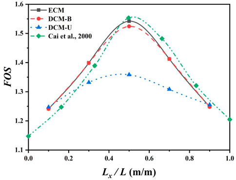
FIGURE 4. Effects of pile position on pile–soil stability considering damage constitutive simulation.
The observations are further expounded in Figures 5–7, which present the positional variation of a slip surface for elastic and damage constitutive models. The depth development of cracks on the pile is marked on the right side of the simulated pile. It can be seen in Figures 5–7 that the unstable slip surface will not pass through the pile when the pile installation location is close to the slope toe or crest. When the pile is positioned close to the middle of the slope (Figure 6), slope failure passes through the pile. Meanwhile, the different types of constitutive models reflect various responses of the piles. Cracks appear in the piles of DCM-B and DCM-U when the pile position is close to the middle of the slope, causing the reduction of the FOS. It can be seen that the level extension of cracks in the under-reinforced pile is much deeper than that in the balanced-reinforced pile. Cracks develop across the cross-section of the under-reinforced pile, while cracks are just presented on the concrete cover of the balance-reinforced pile. Hence, the FOS obtained from DCM-U is smaller than that calculated by the ECM and DCM-B. The damage constitutive model can reflect the influence of cracks on the tensile strength of the pile, which would make a more precise and realistic analysis of the slope stability. The existence of cracks on the pile is not negligible in slope engineering, which would decrease the FOS of the slope. The traditional elastic constitutive model regarded piles as a material without damage, and hence, the stability of the slope will be overestimated. The overestimated factor of slope stability is potentially dangerous in geotechnical engineering. Therefore, it is necessary to simulate piles by the damage constitutive model in pile–slope stability analysis.
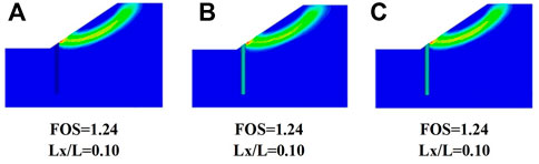
FIGURE 5. Positional variation of the slip surface at the toe of the slope for (A) the ECM, (B) DCM-U, and (C) DCM-B.
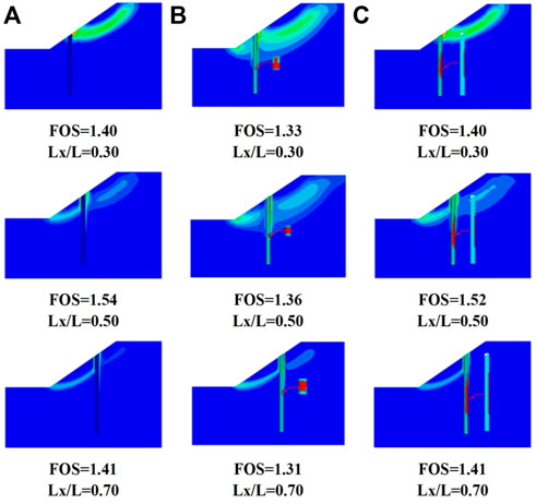
FIGURE 6. Positional variation of the slip surface near the middle of the slope for (A) the ECM, (B) DCM-U, and (C) DCM-B.
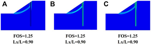
FIGURE 7. Positional variation of the slip surface at the top of the slope for (A) the ECM, (B) DCM-U, and (C) DCM-B.
Figure 8 represents the relationship between the pile’s reinforcement ratio and the FOS on the slope. The reinforcement ratio could be equivalent to the tensile strength of the pile (ft) in this study. The five damage constitutive models with pile positions (Lx/L = 0.1, 0.3, 0.5, 0.7, and 0.9) were compared. When the pile was installed near the top or toe of the slope (Lx/L = 0.1 and 0.9), the ft affected the FOS slightly. It can be indicated that the FOS, which is the pile position close to the middle of the slope, increases to a constant value in the whole range of ft. The peak value of the FOS appeared when the ft was approximately 30 MPa, which means the pile is a balance-reinforced pile. When the pile is under-reinforced, the ft is less than that of the balance-reinforced pile, and hence, the FOS would be reduced. In addition, the over-reinforced pile made a small contribution to the FOS, which is uneconomical in engineering. This is because the tensile failure would occur on the concrete of the pile instead of the bar. The optimum reinforcement ratio of the pile could be determined by the damage constitutive model at specific slope engineering, which can avoid the appearance of the under-reinforced and over-reinforced piles.
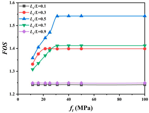
FIGURE 8. Effects of reinforcement ratio on pile–soil stability considering damage constitutive simulation.
Figure 9 summarizes the distribution of pile behavior characteristics along the depth under the action of landslide, including 1) horizontal displacement, 2) bending moment, 3) shear force, and 4) soil pressure. Pile responses at the specific position were obtained from elastic (ECM) and damage constitutive simulation (DCM-B). The results observed from the ECM and DCM-B are consistent with each other only at Lx/L = 0.1 and 0.9, respectively.
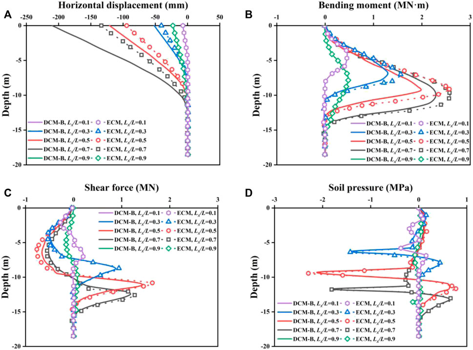
FIGURE 9. Pile behavior characteristics of (A) horizontal displacement, (B) bending moment, (C) shear force, and (D) soil pressure for elastic and damage constitutive models.
It can be seen from Figure 9A that the lateral deformation is reduced to zero at a depth of approximately 13 m. The horizontal deformation of the pile top of the DCM-B at Lx/L = 0.7 is the biggest, with a value of 210 mm. The slightest lateral deformation of the pile toe is 7.2 mm at Lx/L = 0.1. The displacement of the ECM is smaller by 57% than that of the DCM-B at Lx/L = 0.7, which is an enormous difference. The pile deformation calculated by the DCM-B is more significant than the ECM. Nevertheless, the bending moments of the pile obtained from DCM-B are smaller than that from the ECM at Lx/L = 0.3, 0.5, and 0.7.
Figure 9B shows that the bending moment increases at first and then decreases along the depth. The maximum bending moments at all pile positions occur at the boundary between the natural soil and bedrock. The reason for this phenomenon is that Young’s modulus (E) of natural soil (200 MPa) is relatively smaller than that of bedrock (3000 MPa), which has been shown in Table 1. The apparent distinction of E at the boundary would lead to the stress concentration of the pile, and hence, the maximum bending moment was caused. Additionally, the difference in internal forces between the DCM-B (2.0 MN⋅m) and the EMC (2.6 MN⋅m) is most significant at Lx/L = 0.5.
A similar observation can be found in Figure 9C, which plots the distribution of shear force along the depth. At Lx/L = 0.5, the maximum negative and positive shear force of DCM-B is 17% and 18%, respectively, smaller than those of the ECM. It can be observed that the distribution law of shear force with different pile positions and constitutive models is similar. With the increase of depth, the maximum negative shear force occurs first, and then the maximum positive shear force appears. The depths, where the shear force of piles located at Lx/L = 0.1, 0.3, 0.5, 0.7, and 0.9 is zero, are approximately 5.5, 7.5, 9.5, 10, and 8 m, respectively. Concurrently, the bending moment reaches the maximum value at the corresponding depth where the shear force is zero.
The variations of soil pressure along the depth are presented in Figure 9D. The maximum soil pressure of the pile at Lx/L = 0.1 (0.37 MPa) and 0.9 (0.12 MPa) is smaller than that at other positions, which indicates that the reinforced effect of the pile on the soil is slightly at the top or toe of the slope. At Lx/L = 0.5, the DCM-B results for soil pressures disagree slightly with the data observed by the ECM at 9.0-m and 11.7-m depth. It is expected that the pile is to be installed at the middle of the slope (Lx/L = 0.5), there is an apparent agreement of the simulated data for the soil pressure in the DCM-B and the ECM.
Figure 9 further explains the dissimilarity of FOS in DCM-B and ECM piles. The neglect of pile plastic failure rigidity tends to overestimate the pile capacity. The damage constitutive model can reflect the irreversible plastic deformation of the balance-reinforced pile. Therefore, compared to the elastic constitutive model, the damage model predicted larger lateral displacements and a smaller internal force in the pile at a specific condition.
The purpose of the current study was to propose a damage constitutive model to assess the stability of the pile-reinforced slope. The pile was simulated by the damage constitutive model to investigate the influence of the pile’s installation position and reinforcement ratio on the stability of the pile-reinforced slope. It has been demonstrated that the FOS calculated by the elastic and damage constitutive models are different only when the pile was damaged. The difference in the FOS between the ECM and DCM could be more than 12% when Lx/L was equal to 0.5. The second significant finding is that the influence of the reinforcement ratio on a pile-reinforced slope could be reflected by the damage constitutive model. The balance-reinforced pile (FOS = 1.54 and Lx/L = 0.5) increased the FOS by 14% more than the under-reinforced pile (FOS = 1.36 and Lx/L = 0.5). Moreover, the horizontal displacement, bending moments, shear force, and soil pressure along the pile shaft versus the depth below the ground surface were studied. The results illustrated that the traditional elastic damage model would overestimate the internal force in a pile, which can be visibly detected in the bending moments (the maximum difference of bending moment is 30%). The advantage of the damage constitutive model is that the existence of a crack on a pile can be expressed by the reduction of tensile strength, which provides the reference for the slope engineering design.
The original contributions presented in the study are included in the article/Supplementary Material; further inquiries can be directed to the corresponding author.
J-HJ: investigation, validation, and methodology. X-LH: post-processing data and analysis and writing—original draft. XS: writing—review and editing. XN: numerical simulation. YQ: methodology. WX: analysis.
The authors declare that the research was conducted in the absence of any commercial or financial relationships that could be construed as a potential conflict of interest.
All claims expressed in this article are solely those of the authors and do not necessarily represent those of their affiliated organizations, or those of the publisher, the editors, and the reviewers. Any product that may be evaluated in this article, or claim that may be made by its manufacturer, is not guaranteed or endorsed by the publisher.
Ashour, M., and Ardalan, H. (2012). Analysis of pile stabilized slopes based on soil–pile interaction. Comput. Geotechnics 39, 85–97. doi:10.1016/j.compgeo.2011.09.001
Bai, B., Wang, Y., Rao, D., and Fan, B. (2022). The effective thermal conductivity of unsaturated porous media deduced by pore-scale SPH simulation. Front. Earth Sci. (Lausanne). 10. doi:10.3389/feart.2022.943853
Bai, B., Yang, G., Tao, L., and Yang, G. (2019). A thermodynamic constitutive model with temperature effect based on particle rearrangement for geomaterials. Mech. Mater. 139, 103180. doi:10.1016/j.mechmat.2019.103180
Bai, B., Zhou, R., Cai, G., Hu, W., and Yang, G. (2021). Coupled thermo-hydro-mechanical mechanism in view of the soil particle rearrangement of granular thermodynamics. Comput. Geotechnics 137 (8), 104272. doi:10.1016/j.compgeo.2021.104272
Bakri, M., Xia, Y. Y., and Wang, H. B. (2014). Numerical analysis of stabilization of slopes overlying bedrock using piles and effect of socketed length of pile on stability. Appl. Mech. Mater. 580, 424–431. Trans Tech Publications Ltd. doi:10.4028/www.scientific.net/amm.580-583.424
Cai, F., and Ugai, K. (2000). Numerical analysis of the stability of a slope reinforced with piles. Soils Found. 40 (1), 73–84. doi:10.3208/sandf.40.73
Cedolin, L., Darwin, D., Ingraffea, A. R., Pecknold, E. A., and Schnobrich, W. C. (1982). Concrete cracking.” State of the art Rep. on finite element analysis of reinforced concrete. New York: ASCE, 204–233.
Chen, H., Zhang, G., Chang, Z., Wen, L., and Gao, W. (2021). Failure analysis of a highway cut slope with anti-slide piles. Geofluids 2021, 6622214. doi:10.1155/2021/6622214
Chen, Z., Wang, Z., Xi, H., Yang, Z., Zou, L., Zhou, Z., et al. (2016). Recent advances in high slope reinforcement in China: Case studies. J. Rock Mech. Geotechnical Eng. 8 (6), 775–788. doi:10.1016/j.jrmge.2016.11.001
Cheng, Z., and Jeremić, B. (2009). Numerical modeling and simulation of pile in liquefiable soil. Soil Dyn. Earthq. Eng. 29 (11-12), 1405–1416. doi:10.1016/j.soildyn.2009.02.008
Comodromos, E. M., Papadopoulou, M. C., and Rentzeperis, I. K. (2009). Effect of cracking on the response of pile test under horizontal loading. J. Geotech. Geoenviron. Eng. 135 (9), 1275–1284. doi:10.1061/(asce)gt.1943-5606.0000069
Dai, Z., Yang, J., Dai, R., and Zhu, Q. (2022). Three-dimensional and threefold nonlinear numerical modeling for slope-stabilizing pile. KSCE J. Civ. Eng. 26, 4390–4406. doi:10.1007/s12205-022-1474-6
Gu, X. J., Zhou, T. Q., and Lu, S. L. (2014). Stability analysis on anti-slide pile to reinforce slope based on ABAQUS. Appl. Mech. Mater. 580, 711–714. Trans Tech Publications Ltd. doi:10.4028/www.scientific.net/amm.580-583.711
Harries, K. A., Zeno, G., and Shahrooz, B. (2012). Toward an improved understanding of shear-friction behavior. ACI Struct. J. 109 (6), 835.
Hassen, G., Dias, D., and de Buhan, P. (2009). Multiphase constitutive model for the design of piled-embankments: Comparison with three-dimensional numerical simulations. Int. J. Geomech. 9 (6), 258–266. doi:10.1061/(asce)1532-3641(2009)9:6(258)
He, Y., Hazarika, H., Yasufuku, N., and Han, Z. (2015c). Evaluating the effect of slope angle on the distribution of the soil–pile pressure acting on stabilizing piles in sandy slopes. Comput. Geotechnics 69, 153–165. doi:10.1016/j.compgeo.2015.05.006
He, Y., Hazarika, H., Yasufuku, N., Han, Z., and Li, Y. (2015a). Three-dimensional limit analysis of seismic displacement of slope reinforced with piles. Soil Dyn. Earthq. Eng. 77, 446–452. doi:10.1016/j.soildyn.2015.06.015
He, Y., Hazarika, H., Yasufuku, N., Teng, J., Jiang, Z., and Han, Z. (2015b). Estimation of lateral force acting on piles to stabilize landslides. Nat. Hazards (Dordr). 79 (3), 1981–2003. doi:10.1007/s11069-015-1942-0
Henke, S. (2010). Influence of pile installation on adjacent structures. Int. J. Numer. Anal. methods geomechanics 34 (11), 1191–1210. doi:10.1002/nag.859
Huang, Y., Xu, X., and Mao, W. (2020). Numerical performance assessment of slope reinforcement using a pile-anchor structure under seismic loading. Soil Dyn. Earthq. Eng. 129, 105963. doi:10.1016/j.soildyn.2019.105963
Itasca (2006). Fast Lagrangian analysis of continua in 3 dimensions. Minneapolis, USA: User’s Manual, Itasca Consulting Group. Version 3.1.
Jamsawang, P., Bergado, D. T., and Voottipruex, P. (2015). “Full-scale tests on stiffened deep cement mixing piles including three-dimensional finite element simulation,” in Ground improvement case histories (Oxford: Butterworth-Heinemann), 31–77.
Jeong, S., Kim, B., Won, J., and Lee, J. (2003). Uncoupled analysis of stabilizing piles in weathered slopes. Comput. Geotechnics 30 (8), 671–682. doi:10.1016/j.compgeo.2003.07.002
Jiang, Q., Qi, Z., Wei, W., and Zhou, C. (2015). Stability assessment of a high rock slope by strength reduction finite element method. Bull. Eng. Geol. Environ. 74 (4), 1153–1162. doi:10.1007/s10064-014-0698-1
Kavitha, P. E., Beena, K. S., and Narayanan, K. P. (2016). A review on soil–structure interaction analysis of laterally loaded piles. Innov. Infrastruct. Solut. 1 (1), 14–15. doi:10.1007/s41062-016-0015-x
Larsson, S., Malm, R., Charbit, B., and Ansell, A. (2012). Finite element modelling of laterally loaded lime–cement columns using a damage plasticity model. Comput. Geotechnics 44, 48–57. doi:10.1016/j.compgeo.2012.03.004
Lee, C. Y., Hull, T. S., and Poulos, H. G. (1995). Simplified pile-slope stability analysis. Comput. Geotechnics 17 (1), 1–16. doi:10.1016/0266-352x(95)91300-s
Lin, Y. L., Cheng, X. M., Yang, G. L., and Li, Y. (2018). Seismic response of a sheet-pile wall with anchoring frame beam by numerical simulation and shaking table test. Soil Dyn. Earthq. Eng. 115, 352–364. doi:10.1016/j.soildyn.2018.07.028
Maekawa, K., and Qureshi, J. (1997). Stress transfer across interfaces in reinforced concrete due to aggregate interlock and dowel action. Dob. Gakkai Ronbunshu 1997 (557), 159–172. doi:10.2208/jscej.1997.557_159
Martin, G. R., and Chen, C. Y. (2005). Response of piles due to lateral slope movement. Comput. Struct. 83 (8-9), 588–598. doi:10.1016/j.compstruc.2004.11.006
Millard, S. G., and Johnson, R. P. (1984). Shear transfer across cracks in reinforced concrete due to aggregate interlock and to dowel action. Mag. Concr. Res. 36 (126), 9–21. doi:10.1680/macr.1984.36.126.9
Murcia-Delso, J., and Benson Shing, P. (2016). Elastoplastic dilatant interface model for cyclic bond-slip behavior of reinforcing bars. J. Eng. Mech. 142 (2), 04015082. doi:10.1061/(asce)em.1943-7889.0000994
Poulos, H. G. (1995). Design of reinforcing piles to increase slope stability. Can. Geotech. J. 32 (5), 808–818. doi:10.1139/t95-078
Qu, H. L., Luo, H., Hu, H. G., Jia, H. Y., and Zhang, D. Y. (2018). Dynamic response of anchored sheet pile wall under ground motion: analytical model with experimental validation. Soil Dyn. Earthq. Eng. 115, 896–906. doi:10.1016/j.soildyn.2017.09.015
Rahardjo, H., Hritzuk, K. J., Leong, E. C., and Rezaur, R. B. (2003). Effectiveness of horizontal drains for slope stability. Eng. Geol. 69 (3-4), 295–308. doi:10.1016/s0013-7952(02)00288-0
Sharafi, H., and Sojoudi, Y. (2016). Experimental and numerical study of pile-stabilized slopes under surface load conditions. Int. J. Civ. Eng. 14 (4), 221–232. doi:10.1007/s40999-016-0017-2
Sun, H. Y., Wong, L. N. Y., Shang, Y. Q., Shen, Y. J., and Lü, Q. (2010). Evaluation of drainage tunnel effectiveness in landslide control. Landslides 7 (4), 445–454. doi:10.1007/s10346-010-0210-3
Tassios, T. P., and Vintzēleou, E. N. (1987). Concrete-to-concrete friction. J. Struct. Eng. (N. Y. N. Y). 113 (4), 832–849. doi:10.1061/(asce)0733-9445(1987)113:4(832)
Won, J., You, K., Jeong, S., and Kim, S. (2005). Coupled effects in stability analysis of pile–slope systems. Comput. Geotechnics 32 (4), 304–315. doi:10.1016/j.compgeo.2005.02.006
Xu, X., and Huang, Y. (2021). Parametric study of structural parameters affecting seismic stability in slopes reinforced by pile-anchor structures. Soil Dyn. Earthq. Eng. 147, 106789. doi:10.1016/j.soildyn.2021.106789
Yan, M., Xia, Y., Liu, T., and Bowa, V. M. (2019). Limit analysis under seismic conditions of a slope reinforced with prestressed anchor cables. Comput. Geotechnics 108, 226–233. doi:10.1016/j.compgeo.2018.12.027
Yapage, N. N. S., Liyanapathirana, D. S., Poulos, H. G., Kelly, R. B., and Leo, C. J. (2015). Numerical modeling of geotextile-reinforced embankments over deep cement mixed columns incorporating strain-softening behavior of columns. Int. J. Geomech. 15 (2), 04014047. doi:10.1061/(asce)gm.1943-5622.0000341
Zheng, G., Yang, X., Zhou, H., and Chai, J. (2018). Numerical modeling of progressive failure of rigid piles under embankment load. Can. Geotech. J. 56 (1), 23–34. doi:10.1139/cgj-2017-0613
Keywords: damage constitutive model, piles, slope stabilization, safety factor, numerical simulation
Citation: Jiang J-H, Huang X-L, Shu X-R, Ning X, Qu Y and Xiong W-L (2022) Application of a damage constitutive model to pile–slope stability analysis. Front. Mater. 9:1082292. doi: 10.3389/fmats.2022.1082292
Received: 28 October 2022; Accepted: 11 November 2022;
Published: 28 November 2022.
Edited by:
Bing Bai, Beijing Jiaotong University, ChinaCopyright © 2022 Jiang, Huang, Shu, Ning, Qu and Xiong. This is an open-access article distributed under the terms of the Creative Commons Attribution License (CC BY). The use, distribution or reproduction in other forums is permitted, provided the original author(s) and the copyright owner(s) are credited and that the original publication in this journal is cited, in accordance with accepted academic practice. No use, distribution or reproduction is permitted which does not comply with these terms.
*Correspondence: Xi-Long Huang, WGlsb25nSHVhbmcyMDIyQG15LnN3anR1LmVkdS5jbg==
Disclaimer: All claims expressed in this article are solely those of the authors and do not necessarily represent those of their affiliated organizations, or those of the publisher, the editors and the reviewers. Any product that may be evaluated in this article or claim that may be made by its manufacturer is not guaranteed or endorsed by the publisher.
Research integrity at Frontiers
Learn more about the work of our research integrity team to safeguard the quality of each article we publish.