 Likang Tian1,2
 Li-Jun Ouyang
 Jiang-Tao Yu
94% of researchers rate our articles as excellent or good
Learn more about the work of our research integrity team to safeguard the quality of each article we publish.
Find out more
ORIGINAL RESEARCH article
Front. Mater. , 04 November 2022
Sec. Structural Materials
Volume 9 - 2022 | https://doi.org/10.3389/fmats.2022.1056809
The authors proposed using plain engineered cementitious composite (ECC) in construction without aligned reinforcement. In this study, ECC with a tensile strain capacity of up to 10% was produced, which has a comparable deformability level to steel reinforcement. To demonstrate the feasibility of plain ECC construction, five plain ECC beams and two steel reinforced concrete reference beams were prepared, and four-point bending reversed cyclic loading tests were conducted on the beam specimens. The experimental tests indicated that the plain ECC beams showed more stable hysteresis loops with improved energy dissipation capacity, deformation restoring capacity, and lower stiffness degradations than normal RC beams. Two categories of failure modes were observed, i.e., flexural failure mode and shear failure mode. With the increase in the shear span ratio, the failure mode of ECC beams changed from shear failure to flexural failure. Additionally, the increase in sectional dimension had a positive influence on the stiffness and energy dissipation capacity of ECC beams. It is experimentally verified that the plain ECC beams have sufficient load-bearing capacity under static and seismic loading.
Reinforced concrete (RC) structural systems have been widely used in civil engineering practices. Well-designed structures made of concrete and steel reinforcement are expected to be of economic efficiency and adequate reliability in their service lives. However, traditional RC construction costs huge but inefficient human labor. Due to the increasing global aging, labor shortage has become a burning problem for civil engineering construction. Engineers strive to address the issue by developing high-efficient construction technology. Some of them tried to achieve automated construction by using plain concrete. However, the natural weaknesses of concrete, such as brittleness and poor tensile strength, are the main causes of catastrophes when the structures are subjected to extremely impact, such as earthquakes (Sezen et al., 2003; Wang, 2008; Bikçe and Çelik, 2016). Moreover, the fragility of concrete prevents it from becoming a material free from steel reinforcement. To some extent, the application of automated construction is limited due to the absence of appropriate materials.
Fortunately, the brittleness and low tensile strength of concrete can be significantly alleviated by adding short-cut and discontinuous fibers (Sahoo et al., 2015; Liang et al., 2016; Jalasutram et al., 2017; Cai et al., 2021; Liao et al., 2022). Particularly, engineered cementitious composite (ECC) corresponds to the broad fiber-reinforced concrete (FRC) class, and it has emerged with special characteristics such as multiple cracking, strain-hardening behavior, and high tensile ductility. Compared with ordinary concrete or conventional FRC, ECC exhibits much superior tensile strain capacity (typically 2–8%) under increasing tension (Li et al., 2002; Ye et al., 2021; Huang et al., 2022). In recent studies, some investigators developed ECC with tensile strain capacity ranging from 8% to 12%, tensile strength ranging from 4 MPa to 20 Mpa, and a compressive strength ranging from 20 Mpa to 120 Mpa (Yu et al., 2017; Yu et al., 2018a; Yu et al., 2020a; Ding et al., 2020). For the first time, a cementitious material showed comparable ductility to steel reinforcement, and it has been first used to build a frame structure, which succeeded in surviving nine major earthquake impacts (Yu et al., 2018b).
Although a number of researchers have carried out experiments on the mechanical properties of ECC structures, most of the ECC structures were reinforced with longitudinal reinforcement, and very limited was concerned with plain ECC members. Yuan et al. Yuan et al. (2014) presented an experimental research on the mechanical behavior of steel-reinforced ECC beams subjected to reverse cyclic loading. The results indicated that steel-reinforced ECC beams show better seismic performance in terms of load carrying capacity, shear resistance, energy dissipation capacity, and damage tolerance than steel-reinforced concrete beams. Yaw et al. Yaw and Han (2014) conducted a series of experimental research studies on the mechanical properties of the polypropylene (PP) fiber reinforced ECC beams under reverse cyclic loading. The test results indicated that the PP-ECC beams can achieve multiple saturated cracking behavior, and the dissipated energy of the PP-ECC beam is 2.9 times that of the corresponding concrete beam. To verify the feasibility of using ultra-high ductility cementitious composites (ECCs) for construction without steel reinforcement, Yu et al. Yu et al. (2018b) carried out a series of experimental research studies on the mechanical properties of ECC at material, component, and structure levels, and the feasibility of non-steel reinforced ECC structure was preliminarily confirmed. In summary, as a material with high ductility and excellent energy dissipation capacity, ECC has the potential for automatic construction, but the seismic performance of plain ECC structures has never been fully studied.
This study presents an experimental research on the seismic performance of ECC flexural members without aligned reinforcement. The influence of shear span ratio and sectional dimension on the seismic performance of plain ECC beams is highlighted. Based on a series of cyclic loading tests on seven specimens, including five ECC beams and two corresponding RC beams subjected to reverse cyclic loading, investigation and analysis have been carried out on crack pattern, failure mode, hysteretic loops, skeleton curves, stiffness degradation, ductility, energy dissipation capacity, and deformation recovery ability.
The mixture of ECC used in this study is designed as follows. Ordinary Portland cement with a 28-day nominal compressive strength of 52.5 MPa was used as a binder material, and sand was adopted as the fine aggregate. Fly ash was chosen as a supplementary cementitious material to adjust the compressive strength and modulus of elasticity of the ECC. The material proportions of ECC are presented in Table 1. In this research, a 2.0% polyethylene (PE) fiber volume fraction used as a reinforcement material was added to the ECC matrix (Yoo and Banthia, 2022). The tensile strength and elastic modulus of the PE fiber are 2.9 Gpa and 116 Gpa, respectively. The properties of the PE fiber supplied by the manufacturer are given in Table 2.
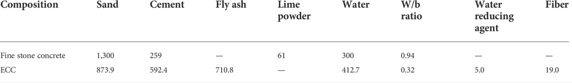
TABLE 1. ECC material mixing proportion (kg/m3).

TABLE 2. Properties of PE fiber.
To further illustrate the properties of the ECC used in this study, especially for ductility, Figure 1 shows two typical curves, i.e., tensile stress–strain curves (Figure 1A) and compressive stress–strain curves (Figure 1B). Table 3 gives the mechanical properties obtained through the uniaxial tensile test and uniaxial compressive test of ECC. Clearly, ECC exhibits superior characteristics of tensile strain-hardening and multi-cracks. The average tensile strength of ECC is 5.69 MPa, and the average and maximum tensile strain capacities of ECC are 10.59% and 12.13%, respectively (Figure 1A), having the similar deformability level of steel. As shown in Figure 1B, at 8.0% compressive strain, ECC exhibits ductility at a high stress level. The average compressive strength is 20.79 MPa.
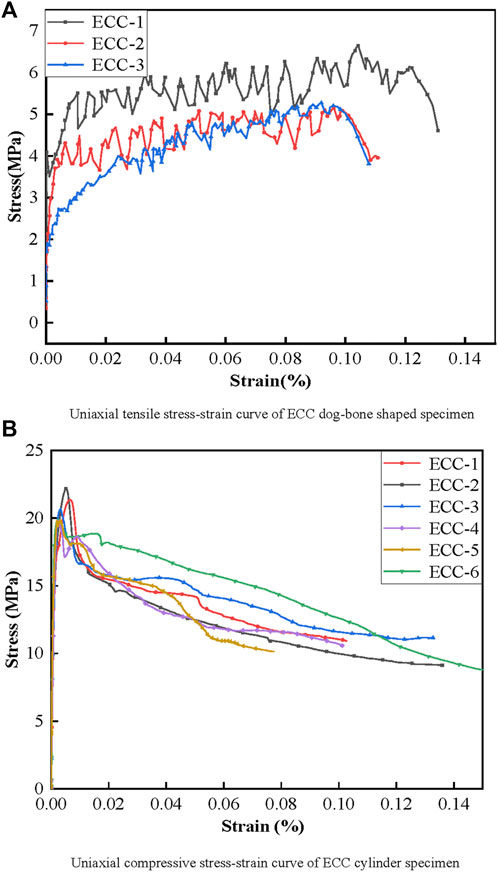
FIGURE 1. Typical tensile stress–strain and compressive stress–strain curves.
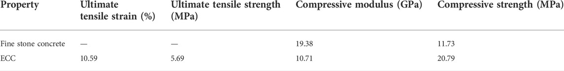
TABLE 3. Mechanical properties of materials used in ECC and fine stone concrete.
It is widely known that the shear span ratio is an important parameter for the design of structural safety. In addition, it was found that the geometry size had an obvious influence on the mechanical properties of ECC (Yu et al., 2020b). Therefore, five plain ECC beams with different section dimensions and shear span ratio were designed in this study. All five beams were cast utilizing the same mix proportion listed in Table 1. Two other reference RC beams were designed with the same dimensional size and shear span ratio as that of ECC for equal comparison. The yield tensile strength and the peak tensile strength of longitudinal steel reinforcement with a diameter of 8 mm are 280.35 MPa and 392.49MPa, respectively. The geometry and reinforcement details of beams are illustrated in Figure 2, and the longitudinal reinforcement ratio of RC beams is 1.0%. In this study, the ECC beams are marked UC-1, UC-2, UC-3, UC-4, and UC-5 and two corresponding RC beams are labeled RC-1 and RC-2. Detailed information about the specimens is given in Table 4.

FIGURE 2. Dimensions, size, and reinforcement details of specimens.
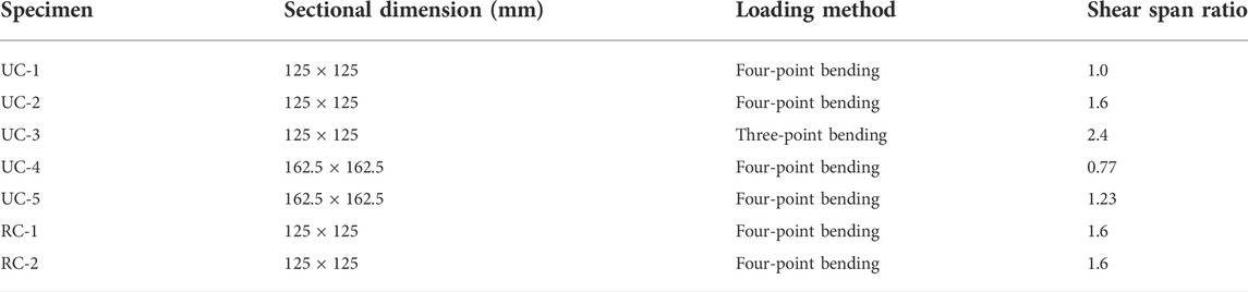
TABLE 4. Design parameters of specimen.
The test setup and details of instrumentation are shown in Figure 3. The cyclic loading tests were performed on a 300-kN hydraulic loading system. Four strain gauges were pasted on the side surfaces of each specimen, as shown in Figure 3, and three linear variable differential transformers (LVDTs) were employed to measure the vertical displacement of the specimens, which were installed at three equal points along the span.
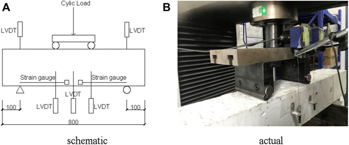
FIGURE 3. Test setup. (A) Layout of the four-point loading. (B) Actual loading test
As shown in Figure 3, the loading span is 600 mm and the supporting boundary of the beam is articulated in the four-point bending test. The low cyclic loading was applied by controlled displacement. The loading procedure was divided into two stages. First, only one cycle was imposed at equal load intervals before yielding displacement (
Figure 4 shows the failure modes of all beams subjected to cyclic loading. From the test, two typical failure modes were observed: shear failure and flexural failure. The failure modes of each specimens are listed in Table 5.
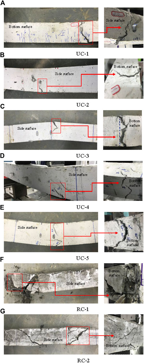
FIGURE 4. Crack patterns and failure modes for all the test specimens. (A) Shear failure of UC-1. (B) Flexural failure of UC-2. (C) Flexural failure of UC-3. (D) Shear failure of UC-4. (E) Flexural failure of UC-5. (F) Shear failure of RC-1. (G) Shear failure of RC-2.
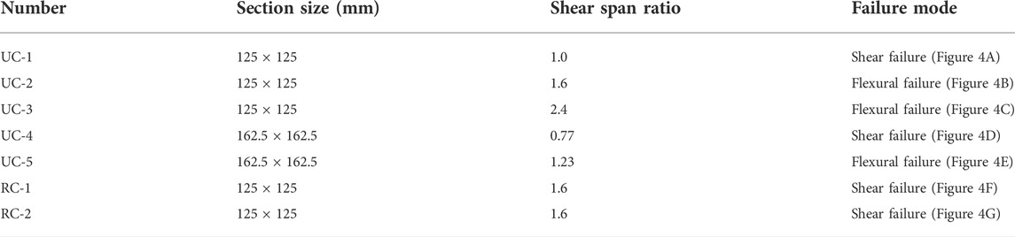
TABLE 5. Failure modes of test specimens.
For ECC beams, the forward–backward deflection of beams increased linearly with the increase of load in the initial stage. The first crack appeared on the bottom surface of the beams when the tension side of the flexural section reached its cracking strength, and the bearing capacity of the section was reduced briefly. Soon after the fibers near the crack exhibited their bridging effect, the flexural bearing capacity of the cracking section would be enhanced with continuous crackle. When the load increased unceasingly, the flexural beam came into a multi-cracking stage, and a trend of fluctuating growth for the load was observed with cracks emerging in the bending–shearing zone of the beams. Along with deflection growth, the width and length of existing cracks increased with no new cracks emerging. Under forward load, the main existing cracks on the bottom surface gradually went through the whole height of the beam. In contrast, reverse loading would cause crack closure, and the deflection of the beams would increase dramatically with slowly increasing load.
Both RC beams failed in the shear-flexural region with large shear cracks. For specimen RC-2, flexural cracks initiated in the pure bending section. Then, cracks in the flexural zone propagated toward the shear-flexural side with an angle of approximately 45°. After that, the first diagonal cracks formed. As the load increased, there was no further propagation of cracks in the flexural zone, while the diagonal cracks in the shear-flexural zone expanded and further developed. During the ultimate load stage, the specimens experienced a sudden failure. Continuous diagonal cracks in the shear-flexural region were observed, as shown in Figure 4G. The cracking process for specimen RC-1 was similar to that of specimen RC-2 in the early stage of loading. However, the damage extent of specimen RC-1 was more intense. Upon further loading, the bottom concrete cover of the specimen bulged, and the concrete in the shear-flexural region spalled finally. Meanwhile, the longitudinal bars of the corresponding parts bent and bulged outward, as shown in Figure 4F.
Specimens UC-2, UC-3, and UC-5 designed with a higher relative shear span ratio were characterized by flexural failure, as shown in Figures 4B,C,E. For instance, the failure process for specimen UC-2 is given as follows: in the initial stage, several fine cracks appeared in the flexural zone. During the loading cycles, a few diagonal cracks could be found at the shear bending section, but no further propagation of these cracks was observed. Multiple tiny cracks formed and developed in the bending zone. As the deflection increased, the cracks expanded gradually, and eventually a major transverse crack developed and propagated from one bottom to the opposite top side at the mid-span. At that moment, the flexural strength of this side reached its peak strength. Finally, UC-2 failed in one-side flexure. It is noted that the opposite side loading did not reach its corresponding peak. Specimens UC-1 and UC-4 with a low shear span ratio failed in the shear mode in the flexural-shear zone. Different from specimen RC-1 and RC-2, several flexural cracks were still formed and developed because of the excellent shear performance of the ECC. Meanwhile, compared with RC beams, the great deformation capacity and the development of multi-cracks ensured that the shear failure of the ECC specimens became more gradual and exhibited more ductile behavior. As expected, there was no spalling occurrence on the ECC beams and the specimens still maintained good integrity, which is mainly attributed to the ECC’s superior multi-crack formation and strain-hardening capability.
The hysteresis loops are the basis to analyze the nonlinear seismic response of the beams since they effectively reflect the ultimate bearing capacity, stiffness degradation, and energy dissipation of the beams subjected to low-cycle reversed loading. As plotted in Figure 5, observations could be inferred in analyzing the load-drift response as follows:
1) All specimens exhibited linear behavior before yielding, and the lateral stiffness has little change at this stage. After yielding, the hysteresis loops appeared in different shapes. The hysteresis loops of the RC beams were “inverted-S-type,” and a pinch effect appeared because of the opening and closing of cracks or the debonding of steel bars. In contrast, the hysteresis loops of the ECC beams presented a typical “Z-type.” Compared with RC beams, the ECC beams exhibited more pronounced pinching and flatter hysteretic curves, and the hysteretic response was more stable with full hysteresis loops.
2) Compared with RC-1 and RC-2 (Figures 5F,G), the hysteretic loops are plumper and more stable for the UC-2 (Figure 5B). Meanwhile, the ultimate drift of ECC beam is up to 10%, while the RC beam was only around 6%. The characteristics described previously indicated that the ECC beams represented much better deformation than RC beams. This is mainly due to the superior tensile and compressive strain capacities of the ECC, which improves the ductility of ECC members and avoids premature failure.
3) The ECC beams with higher shear span ratios (i.e., λ = 2.4, UC-3, Figure 5C) show a more ductile response than those with lower shear span ratios (i.e., λ = 1.6, UC-2, Figure 5B and λ = 1.0, UC-1, Figure 5A). With the increase in shear span ratio, the failure mode of specimens gradually converts from shear failure to flexural failure. Notably, although ECC-1 and RC beams experienced shear failure, the deformation capacity and ductility of ECC-1 were better than those of RC beams, and the multi-cracks in the ECC-1 ensured a more ductile failure. In summary, the ECC beams show better seismic performance than the RC rivals when the shear span ratio is equal.
4) For the specimens with different sectional dimension, the hysteretic loops for the specimens with smaller sectional dimension (i.e., Figures 5A,B) show relatively plumper and more stable hysteretic characteristics than those with larger dimension (i.e., Figures 5D,E).
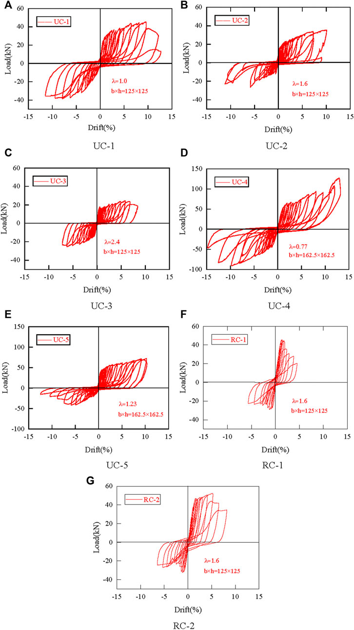
FIGURE 5. Hysteretic curves. Drift vs. load force hysterestic curves.
The skeleton curves can reflect the strength degradation, stiffness degradation, and deformation characteristics of the beams. Figure 6 gives the skeleton curves of all specimens with different shear span ratios and section dimension, and the following is observed:
1) All the skeleton curves develop along a nearly linear line before reaching the yield point. The specimen exhibits plastic characteristics after that point at which the lateral stiffness begins to degrade gradually and the bearing capacity of the specimen reaches its peak. After the peak load, the deformation increases sharply, and the strength starts to degrade due to bulging or spalling of the bottom cover of the specimens. In addition, the ECC beams exhibit strain-hardening characteristics during the loading process.
2) As shown in Figure 6A, the ECC and RC beams behave completely differently. The yield load of the UC-2 was much smaller than that of the RC, whereas the peak load values have no obvious difference, which is mainly attributed to the strain-hardening of ECC beams after yielding. After the peak loading point, the skeleton curves of RC beams decrease earlier and faster than those of specimen UC-2. It indicated that the ECC beams exhibit a better ductility response.
3) In Figure 6B, the skeleton curves behave clear shift with the shear span ratio changing. The slopes for the ascent stage of the skeleton curves decrease with the increase of the shear span ratio, which denotes the lateral stiffness and the peak load decrease in a certain range. However, when reaching the peak load, the skeleton curves of the specimens with a higher shear span ratio decrease more slowly and stably. In addition, it can be seen from Figure 6C that there are similar observations between the UC-4 and UC-5. Therefore, it proves that the ductility performance is effectively improved by the increasing shear span ratio.
4) As illustrated in Figure 6D, by comparing the specimens, i.e., UC-1 and UC-4, it is found that specimens with a larger relatively sectional dimension showed much worse ductile behavior. Furthermore, specimens with a larger sectional dimension had a higher peak load but significantly lower ultimate displacement and deformation ability.
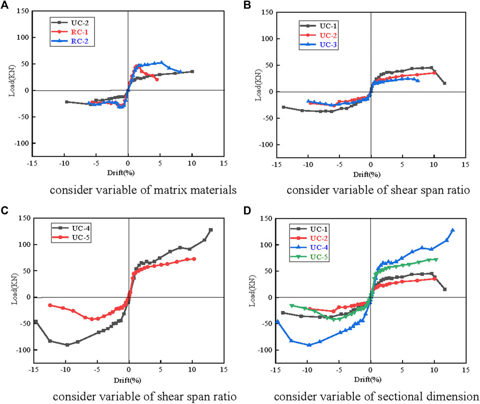
FIGURE 6. Skeleton curves. Drift vs. load force skeleton. (A) Difference induced by introducing ECC. (B) Influence of shear span ratio. (C) Influence of shear span ratio. (D) Influence of sectional dimension.
The stiffness degradation reflects the cumulative damage level of the beams under reverse cyclic loading. In this study, as illustrated in Figure 7, secant stiffness is used to represent the stiffness of the specimen, which is defined as the slope of the straight line joining the peaks of the positive and negative cycles. Secant stiffness for each hysteresis loop is calculated with the following equation:
where
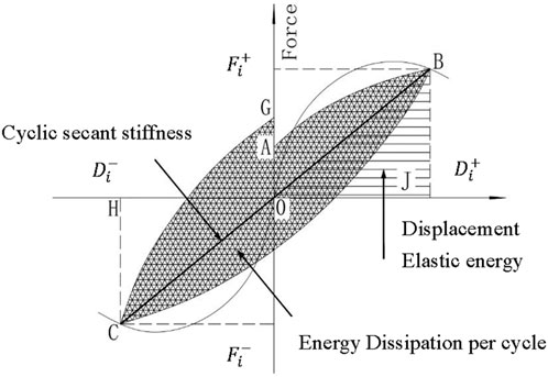
FIGURE 7. Secant stiffness calculation model.
The stiffness degradation curves of all specimens considering the section dimension and shear span ratio are presented in Figure 8. All the stiffness degradation curves represented a remarkable characteristic as follows. During the initial stage of loading, the lateral stiffness decreased rapidly due to the appearance of many cracks. After 5% drift ratio, with the full development of cracks, the plastic deformation increases greatly, which contributes to the slow stiffness degradation of the specimen. Therefore, the stiffness degradation law can be described as “fast followed by slow”.
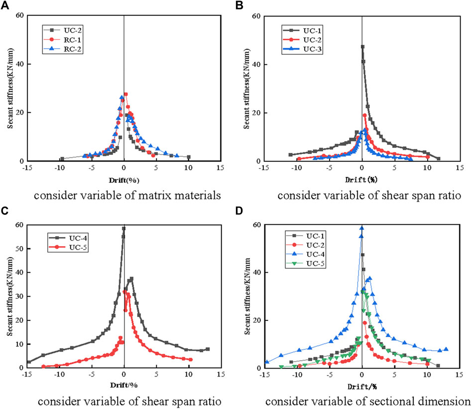
FIGURE 8. Stiffness degradation. (A) Difference induced by introducing ECC. (B) Influence of shear span ratio. (C) Influence of shear span ratio. (D) Influence of sectional dimension.
Figure 8A compares the stiffness degradation of the specimens with different matrix materials. Compared with RC-1 and RC-2, the initial stiffness of UC-2 was much smaller, mainly attributed to the fact that the elastic modulus of ECC is lower than that of ordinary concrete. However, the stiffness of UC-2 degrades more slowly, and the stiffness difference decreases. This may be explained that during the loading process, relatively wide and large cracks formed in the concrete beam, while small and slender cracks appeared in the ECC beam. These fine cracks made the ECC beams have a considerably higher effective moment of inertia than the RC beams, compensating for the lower elastic modulus.
The shear span ratio has a significant effect on the stiffness degradation of all ECC specimens. As shown in Figure 8B and Figure 8C, the initial stiffness of the specimens decreases significantly with the increase in shear span ratio, but with a more slower stiffness degradation with a higher shear span ratio (λ = 2.4). Hence, the stiffness degradation curves again demonstrate that a better ductile response is exhibited by the ECC beams with a higher shear span ratio.
As illustrated in Figure 8D, specimens with a larger sectional dimension showed a much higher initial stiffness and more gentle stiffness degradation.
Ductility is an important parameter that characterizes structural reliability, which refers to the ability of the beams to undergo amplitude cyclic deformations without a significant reduction in bearing capability.
The ductility factor, defined as Eq. 2, is used to quantitatively evaluate the ductility of specimens with different design parameters.
where
The ductility factor is calculated for all beams, including both positive and negative directions, as summarized in Table 6. Compared with the RC beams, the ECC beams show better ultimate rotation and yield rotation, and the ductility factor exhibits a slight increase, such as that the ductility factor of specimen UC-2 is 4.94, which is 1.2 times as much as that of RC-2. It indicates that the ECC beams without aligned reinforcement have good ductility, which is obviously different from the conventional concrete beams that exhibit more brittleness. The ductility factor increases significantly with the increase in of the shear span ratio. For example, the ductility factor of specimen UC-3 is 7.05, which is 1.5 times as much as that of specimen UC-1. It proves that the ductile performance of specimens with a higher shear span ratio is more excellent. In addition, a slight decrease in the ductility factor was observed with increasing sectional dimension. It was majorly because of the shearing effect.
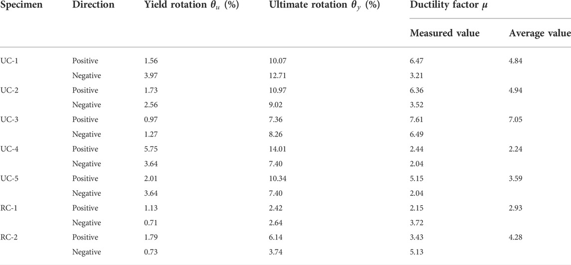
TABLE 6. Ductility factor of test specimens.
Energy dissipation is another basis parameter to estimate the seismic response of the beams. The energy dissipation capacity of the tested specimens is evaluated by the area enclosed by the hysteretic curve, which is usually measured by the cumulative energy consumption at a given displacement level. Figure 9 gives the cumulative energy dissipation curves.
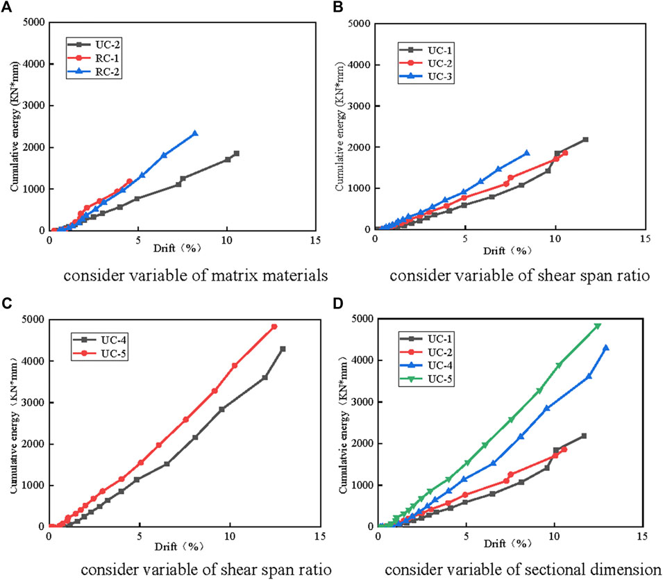
FIGURE 9. Cumulative energy dissipation curves. (A) Difference induced by introducing ECC. (B) Influence of shear span ratio. (C) Influence of shear span ratio. (D) Influence of sectional dimension.
In general, the cumulative energy dissipation of each specimen increased with the increase in load level, and the beams showed good energy dissipation. In the same scenario, greater energy dissipation could be found in the ECC beams than in the RC beams. Meanwhile, weaker energy dissipation could be obtained in the ECC series with a lower shear span ratio. In addition, specimens with larger sectional dimensions, i.e., UC-4 and UC-5, exhibited much higher energy dissipation. This is reasonable because specimens with a large sectional dimension have a relatively high bearing capacity, which enlarged the areas of the hysteresis curves correspondingly.
The deformation recovery capacity has a significant impact on the post-earthquake performance of the beams. The deformation recovery capacity was evaluated by using the residual deformation rate, which was defined by the ratio of residual deformation to ultimate deformation. Also, the deformation recovery index of all beams is summarized in Table 7.
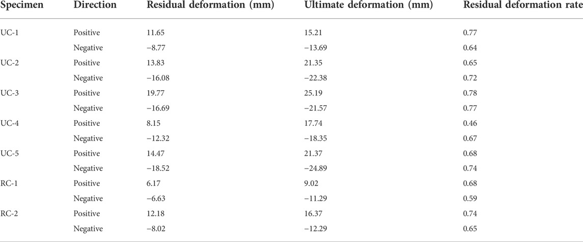
TABLE 7. Deformation recovery index of test specimens.
By comparing specimens UC-1, and RC-2, the residual deformation rate of ECC beams was found to be very close to that of RC beams. Hence, the plain ECC beams exhibit a great deformation recovery ability, which was equivalent to that of RC beams with a unidirectional reinforcement ratio of 1%. It is worth nothing that the change in the shear span ratio and sectional dimension had little influence on the deformation recovery capability of the beams.
The objective of the present study is to explore the seismic performance of ECC beams without aligned reinforcement. Cycle-loading tests were conducted on seven beams with different shear span ratios and sectional dimensions. Based on experimental analysis, the following conclusions can be drawn:
1) ECC shows the characteristics of excellent strain-hardening and superior deformability under tension. The average tensile strain capacity of ECC reached 10.59%, and the maximum exceeded 12.0%. Even at high compressive strain, the ECC retained its ductility with high stress levels.
2) The plain ECC beams shows better ductility than RC beams. The tensile behavior of ECC enables ECC beam prone to flexural failure. When failure occurs in the bending region, the ductility of the ECC beams is 1.2 times that of RC beams.
3) Two typical failure modes of ECC beams were observed in the test, i.e., shear failure and flexural failure. With the increase of the shear span ratio, the failure mode of specimens gradually converts from shear failure to flexural failure. It proves that with proper design, ECC beams can avoid the formation of shear cracks in the shear-flexural region.
4) The increase in the shear span ratio and sectional dimension shows a positive effect on the seismic performance of the ECC beams. With a higher shear span ratio, the ECC beams show more ductile response and better energy dissipation capacity than the specimens with a lower shear span ratio. Specimens with larger sectional dimensions have higher bearing capacity and energy dissipation but relatively lower deflection and ductility at failure.
5) The initial stiffness of ECC beams was lesser than that of RC beams, but the stiffness of ECC beams degrades more slowly. During the loading process, specimens with a relatively large shear span ratio and small sectional dimension show a lower initial stiffness but slower stiffness degradation.
6) Cumulative energy dissipation of each specimen increases with the increase of load level, and the ECC beams show better energy dissipation. Specimens with a larger shear span ratio and sectional dimension exhibit much higher energy dissipation. Nevertheless, the changes in the shear span ratio and sectional dimension have little influence on the deformation recovery capability. The ECC beams without aligned reinforcement exhibit a great deformation recovery ability, which is equivalent to that of RC beams with a reinforcement ratio of 1.0%.
The emergence of ECC provides an option for plain concrete construction in the future, but the studies on the mechanical properties, calculation method, and design theory are just at the very beginning. More systematic studies are urgently needed for this category of structural style for the future potential engineering practice.
The original contributions presented in the study are included in the article/Supplementary Material; further inquiries can be directed to the corresponding author.
LT conducted experiments and data analysis. J-TY made the test plan and analyzed the data. Others contributed to the writing of the manuscript.
The authors declare that the research was conducted in the absence of any commercial or financial relationships that could be construed as a potential conflict of interest.
All claims expressed in this article are solely those of the authors and do not necessarily represent those of their affiliated organizations, or those of the publisher, the editors, and the reviewers. Any product that may be evaluated in this article, or claim that may be made by its manufacturer, is not guaranteed or endorsed by the publisher.
Bikçe, M., and Çelik, T. B. (2016). Failure analysis of newly constructed RC buildings designed according to 2007 Turkish Seismic Code during the October 23, 2011 Van earthquake. Eng. Fail. Anal. 64, 67–84. doi:10.1016/j.engfailanal.2016.03.008
Cai, Z., Liu, F., Yu, J., Yu., K., and Tian, L. (2021). Development of ultra-high ductility engineered cementitious composites as a novel and resilient fireproof coating. Constr. Build. Mat. 288, 123090. doi:10.1016/j.conbuildmat.2021.123090
Ding, Y., Yu, K., and Mao, W. (2020). Compressive performance of all-grade engineered cementitious composites: Experiment and theoretical model. Constr. Build. Mat. 244, 118357. doi:10.1016/j.conbuildmat.2020.118357
Yaw, C. H., and Han, J. B. (2014). The mechanical behavior of fiber reinforced PP ECC beams under reverse cyclic loading. Adv. Mater. Sci. Eng. 2, 1–9. doi:10.1155/2014/159790
Huang, B. T., Zhu, J. X., Weng, K. F., Li, V. C., and Dai, J. G. (2022). Ultra-high-strength engineered/strain-hardening cementitious composites (ECC/SHCC): Material design and effect of fiber hybridization. Cem. Concr. Compos. 129, 104464. doi:10.1016/j.cemconcomp.2022.104464
Jalasutram, S., Sahoo, D. R., and Matsagar, V. (2017). Experimental investigation of the mechanical properties of basalt fiber reinforced concrete. Struct. Concr. 18 (2), 292–302. doi:10.1002/suco.201500216
Li, V. C., Wu, C., Wang, S., Ogawa, A., and Saito, T. (2002). Interface tailoring for strain-hardening polyvinyl alcohol-engineered cementitious composite (PVA-ECC). ACI Mat. J. 99 (5), 463–472.
Liang, X., Wang, Y., Tao, Y., and Deng, M. k. (2016). Seismic performance of fiber-reinforced concrete interior beam-column joints. Eng. Struct. 126, 432–445. doi:10.1016/j.engstruct.2016.08.001
Liao, Q., Su, Y., Yu, J., and Yu, K. (2022). Torsional behavior of BFRP bars reinforced engineered cementitious composites beams without stirrup. Eng. Struct. 268, 114748. doi:10.1016/j.engstruct.2022.114748
Sahoo, D. R., Solanki, A., and Kumar, A. (2015). Influence of steel and polypropylene fibers on flexural behavior of RC beams. J. Mat. Civ. Eng. 27 (8). 0001193. doi:10.1061/(asce)mt.1943-5533.0001193
Sezen, H., Whittaker, A. S., J Elwood, K., and M Mosalam, K. (2003). Performance of reinforced concrete buildings during the August 17, 1999 Kocaeli, Turkey earthquake, and seismic design and construction practise in Turkey. Eng. Struct. 25 (1), 103–114. doi:10.1016/s0141-0296(02)00121-9
Wang, Z. (2008). A preliminary report on the great wenchuan earthquake. Earthq. Eng. Eng. Vib. 7 (2), 225–234. doi:10.1007/s11803-008-0856-1
Ye, J., Cui, C., Yu, J., Yu, K., and Xiao, J. (2021). Fresh and anisotropic-mechanical properties of 3D printable ultra-high ductile concrete with crumb rubber. Compos. Part B Eng. 211, 108639. doi:10.1016/j.compositesb.2021.108639
Yoo, D. Y., and Banthia, N. (2022). High-performance strain-hardening cementitious composites with tensile strain capacity exceeding 4%: A review. Cem. Concr. Compos. 125, 104325. doi:10.1016/j.cemconcomp.2021.104325
Yu, K. Q., Wang, Y. C., Yu, J. T., and Xu, S. L. (2017). A strain-hardening cementitious composites with the tensile capacity up to 8%. Constr. Build. Mat. 137, 410–419. doi:10.1016/j.conbuildmat.2017.01.060
Yu, K. Q., Yu, J. T., Dai, J. G., Lu, Z. D., and Shah, S. P. (2018). Development of ultra-high performance engineered cementitious composites using polyethylene (PE) fibers. Constr. Build. Mat. 158, 217–227. doi:10.1016/j.conbuildmat.2017.10.040
Yu, K. Q., Li, L., Yu, J. T., Xiao, J. Z., Ye, J. H., and Wang, Y. C. (2018). Feasibility of using ultra-high ductility cementitious composites for concrete structures without steel reinforcement. Eng. Struct. 170, 11–20. doi:10.1016/j.engstruct.2019.04.094
Yu, K., Ding, Y., and Zhang, Y. X. (2020). Size effects on tensile properties and compressive strength of engineered cementitious composites. Cem. Concr. Compos. 113, 103691. doi:10.1016/j.cemconcomp.2020.103691
Yu, J. T., Y Dong, F., and H Ye, J. (2020). Experimental study on the size effect of ultra-high ductile cementitious composites. Constr. Build. Mat. 240, 117963. doi:10.1016/j.conbuildmat.2019.117963
Keywords: engineered cementitious composite, seismic performance, failure modes, low cycle loading, construction without reinforcement
Citation: Tian L, Tan Y, Wei X-X, Ouyang L-J, Xu R and Yu J-T (2022) Experimental investigation on seismic performance of plain engineered cementitious composite beams. Front. Mater. 9:1056809. doi: 10.3389/fmats.2022.1056809
Received: 29 September 2022; Accepted: 17 October 2022;
Published: 04 November 2022.
Edited by:
John L. Provis, The University of Sheffield, United KingdomCopyright © 2022 Tian, Tan, Wei, Ouyang, Xu and Yu. This is an open-access article distributed under the terms of the Creative Commons Attribution License (CC BY). The use, distribution or reproduction in other forums is permitted, provided the original author(s) and the copyright owner(s) are credited and that the original publication in this journal is cited, in accordance with accepted academic practice. No use, distribution or reproduction is permitted which does not comply with these terms.
*Correspondence: Jiang-Tao Yu, eXVqaWFuZ3Rhb0B0b25namkuZWR1LmNu
Disclaimer: All claims expressed in this article are solely those of the authors and do not necessarily represent those of their affiliated organizations, or those of the publisher, the editors and the reviewers. Any product that may be evaluated in this article or claim that may be made by its manufacturer is not guaranteed or endorsed by the publisher.
Research integrity at Frontiers
Learn more about the work of our research integrity team to safeguard the quality of each article we publish.