 Weijian Yu1,2,3
 Mingjuan Zhou
94% of researchers rate our articles as excellent or good
Learn more about the work of our research integrity team to safeguard the quality of each article we publish.
Find out more
ORIGINAL RESEARCH article
Front. Mater., 07 December 2022
Sec. Mechanics of Materials
Volume 9 - 2022 | https://doi.org/10.3389/fmats.2022.1056135
In this paper, the properties of superfine cement with different mesh sizes are observed from both macro and micro perspectives through laboratory tests, and the fluidity, stability, and mechanical properties of superfine cement are studied in depth. The results show that increasing the mesh size of superfine cement can reduce the influence of the water-cement ratio on slurry, reduce the fluidity of superfine cement, and enhance its stability. The strength of the superfine cement stone specimen will increase with the increase in cement mesh number, and the higher the mesh number, the shorter the time required for the superfine cement stone specimen to reach its maximum strength. Considering the performance, cost, and storage difficulty, the superfine cement with the mesh size of K700 is more cost-effective. Using K700 superfine cement grout can effectively reduce the impact of geostress on the surrounding rock of the roadway and inhibit the deformation and damage of the surrounding rock.
The state of the coal rock body in the deep roadway is extremely unstable as underground coal mining depths increase, and the deep mine roadway is subjected to both high ground stress and strong mining, causing its surrounding rock to undergo continuous rheological changes or even large deformations (Yu et al., 2019; Yu et al., 2020). As early as the former Soviet Union, the data showed that grouting reinforcement can improve the overall strength of the broken rock mass and effectively improve its mechanical properties. After grouting reinforcement, the strength of siltstone can be improved by more than twice (Perret et al., 2000). Earlier studies in China can be traced back to the end of the last century, Zhang et al. (Zhang et al., 1998a; Zhang et al., 1998b) performed grouting reinforcement on different cracked rock masses and compared the strength properties and deformation characteristics of each fractured rock mass before and after grouting, and used the experimental results to analyze the control mechanism of grouting reinforcement on the deformation of the roadway surrounding rock, which provided a theoretical basis for downhole grouting reinforcement. Yu et al. (Yu et al., 2021a) believe that grouting can fill the broken rock mass and improve the surrounding rock’s integrity and mechanical strength. The surrounding rock’s self-bearing capability and stability can be increased through grouting.
Scholars have always focused their research on the selection and upgrading of grouting materials in order to achieve a good grouting result. In view of the safety problems of polyurethane grouting materials, Feng et al. (Feng et al., 2013) modified the original basis by adding portland cement, and successfully developed a new type of organic-inorganic grouting material that not only improves the mechanical properties but also solves the flammable factors of the original polyurethane, which can be well adapted to the grouting reinforcement in the underground. Using the property that acrylate gel can swell water but not dissolve in water, Jiang et al. (Jiang et al., 2020) added it to the cement slurry and a mixed-coupling agent to improve the force between the two materials, which greatly improved the caking rate of the cement slurry and the strength of the cement slurry after consolidation, as well as the resistance of the cement slurry to dynamic water scouring. Through research on the physical properties of the l red clay paste backfilling material, Yu et al. (Yu et al., 2021b) studied the physical properties of laterite paste filling materials and believed that the strength of laterite paste filling materials and traditional fly ash type filling materials had little difference under the same filling conditions, which not only met the requirements of paste filling technology but also reduced the filling cost.
Cement grouting materials are widely used because of their high strength, good durability, simple material preparation, pollution-free, and low price (Chen and Gu, 1999). However, the particle size of ordinary portland cement is large and the particle size is relatively coarse, so the effect of grouting reinforcement for micro-cracks is poor (Chen, 1998). Zhao et al. (Zhao et al., 2020) modified the ordinary silicate cement grouting material by using sulphoaluminate cement and hydroxypropyl methylcellulose, which effectively shortened the setting time and improved the early strength and water dispersion resistance of the grouting material, and this new cement-based grouting material can ensure the grouting effect and at the same time has good water dispersion resistance. Yan et al. (Yan et al., 2020) added waterborne polyurethane to the sulphoaluminate cement, thereby not only improving the flow and permeability of the cement slurry but also improving the strength, expansion rate, and erosion resistance of the sulfate cement-based grouting material.
Compared with other grouting materials, superfine cement is more cost-effective in grouting performance, material cost, and other factors. Superfine cement is usually prepared by grinding ordinary cement with a special ball mill or Raymond mill, so its particle size is small, which has a significant effect on the grouting reinforcement of fine cracks, and the strength of superfine cement after the consolidation is greatly improved. Guan et al. (Guan et al., 2020) optimized the proportion of superfine sulphoaluminate cement, lime, and gypsum, supplemented by LiAl-layered double hydroxides and organic regulator, which improved the permeability, adhesion and compressive strength of grouting materials, and applied them to deep roadway grouting reinforcement to improve the large deformation of surrounding rock. Li et al. (Guan et al., 2003) adopted the method of adding fly ash, slag refining and other reinforcing components into superfine cement, so as to improve the comprehensive performance of superfine cement grouting material, and studied and analyzed its macro-strength change from the microscopic point of view.
However, there are limited investigations on the performance of portland cement as superfine cement and the related modifications. Portland cement particle refinement can improve its grouting action, and its characteristics will alter dramatically, although not all of these changes are positive (Li and Chen, 2006; Zhang, 2010; Yang, 2019). In addition, the finer the superfine cement particles, the higher the cost and material loss. In order to coordinate the cost, injectability and grouting effect, this paper takes common portland cement grouting materials with different mesh numbers as the research object, studying its basic performance characteristics and different water-cement ratio under the influence of performance change characteristics, and selecting the best mesh, to ensure the improvement of the strength of the broken rock after grouting while reducing unnecessary financial and material losses, to create a higher application value for downhole grouting.
The superfine cement used in this paper is independently ground by Shuiliandong Coal Mine in Binxian County. According to particle size, it can be divided into K600, K700 and K1000 models, and the main mineral composition of the cement is tricalcium silicate (C3S), dicalcium silicate (C2S), tricalcium aluminate (C3A), tetracalcium aluminoferrite (C4AF) and quartz (SiO2). Figure 1 shows the superfine cement used in the experiment.
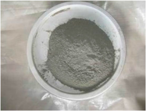
FIGURE 1. Superfine cement.
Through the measurement of the Zhuhai laser particle size analyzer, the particle size distribution was analyzed. The following is the particle size distribution of K600, K700 and K1000 superfine cement used in the experiment.
As shown in Tables 1–3, the average particle size of K600 superfine cement is 12.56 μm, with the median particle size D50 equal to 9.58μm, and there are more large particles with particle size greater than 10 μm, accounting for more than 50% of the total. K700 superfine cement average particle size of 10.55 μm, the median particle size D50 is equal to 8.05 μm, in which most of the cement particles are distributed in the 7.192–14.666 μm range, compared to K600 superfine cement fineness has improved, compared to the particle size of 10 μm above the proportion of large particles has been less than 40%. The average particle size of K1000 superfine cement is 6.86 μm, the median particle size D50 is equal to 5.46 μm, more than 80% of the cement particles are less than 9.12 μm, and the percentage is more than 30% in the range of 4.472–7.192 μm. Through particle size analysis, it can be determined that K600 fineness is 600 mesh, K700 is between 700 mesh and 800 mesh, and k1000 fineness has reached 1,000 mesh. Figure 2 shows the particle size distribution of three superfine cements.
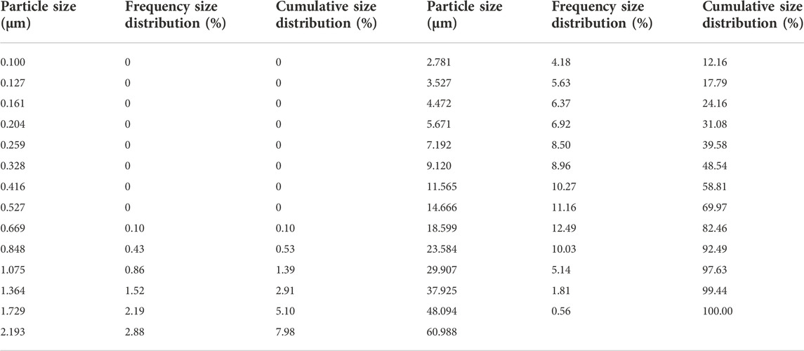
TABLE 1. Particle size distribution of K600 superfine cement.
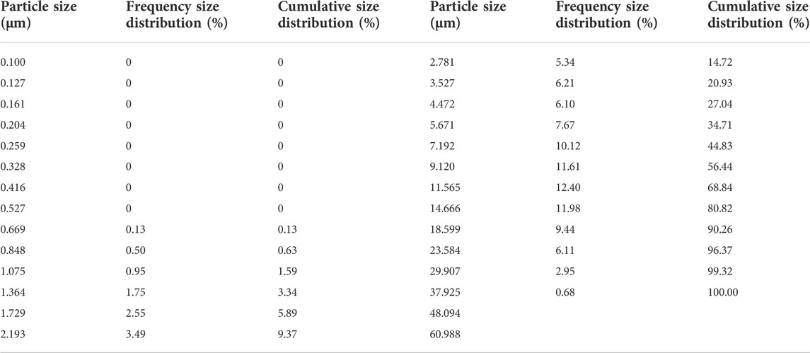
TABLE 2. Particle size distribution of K700 superfine cement.
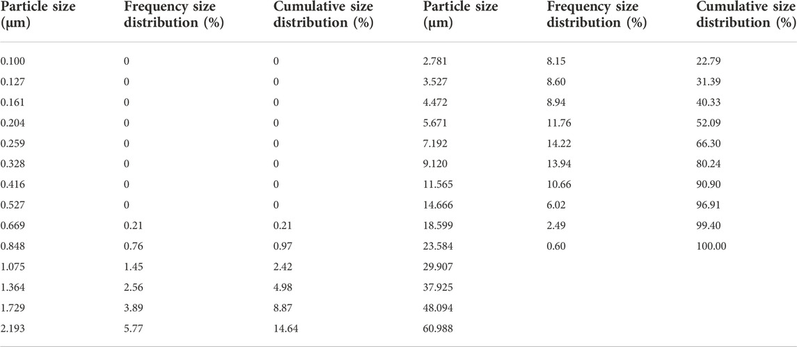
TABLE 3. Particle size distribution of K1000 superfine cement.
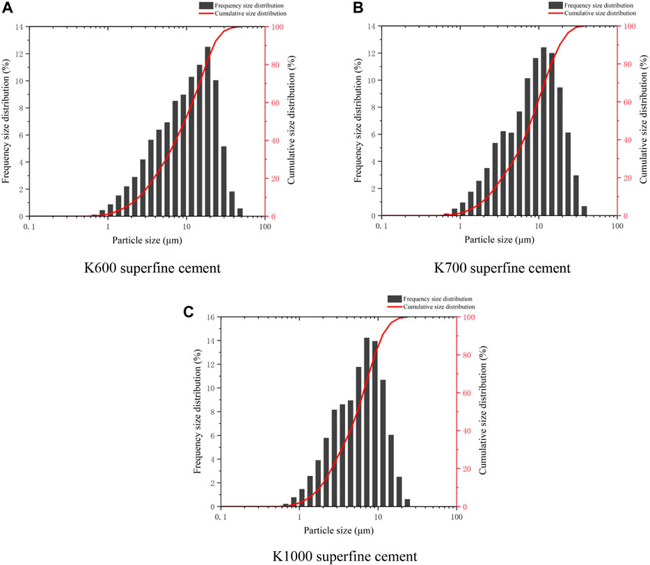
FIGURE 2. The particle size distribution of superfine cement.
In order to analyze the particle size ratio of three specifications of superfine cement more intuitively, appropriate amounts of K600, K700, and K1000 superfine cement were dried to a constant weight in a drying oven and then examined using a scanning electron microscope (SEM). Figure 3 displays electron microscope scans of three types of superfine cement particles at a microscopic magnification of 1,000 times, with the size noted in the figure representing the representative particle size of this type of superfine cement.
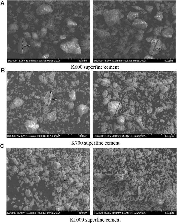
FIGURE 3. SEM of superfine cement particles.
In K600 superfine cement, there are more large-size cement particles, and the large-size cement particles in K700 superfine cement are considerably smaller and more graded, as shown in Figure 3. The fineness of K1000 superfine cement has substantially improved over the previous two, and the majority of the cement particles are small in size, while there are some bigger cement particles. Secondly, from the electron microscope scan of K1000 superfine cement particles, it can be found that some of the fine cement particles have produced the phenomenon of hydration reaction between them, resulting in bonding into clumps, so extra attention is needed to keep the storage environment dry in daily storage.
In order to deeply understand the change of cementation between particles of superfine cement under different mesh sizes and water-cement ratios from a microscopic perspective, K600 and K700 superfine cement stone test blocks with a water cement ratio of 0.45 and K700 and K1000 superfine cement stone test blocks with a water cement ratio of 0.5 were selected for comparison, and the selected samples were immersed in anhydrous ethanol for a while with appropriate K600 and K700, K1000 superfine cement was dried in the drying oven to constant weight and then observed by scanning electron microscope (SEM).
By comparing the scanning results of different meshes of superfine cement test blocks with the same water-cement ratio in Figure 4, it can be found that due to the reduction of cement particle size, the hydration reaction between particles is more thorough, the particle sense of internal structure is greatly reduced, the cementation between cement particles is stronger, and more flocculent particles are transformed into blocky ones. However, it can also be seen that the water demand is greater because of the reduction of particle size, micro-cracks, and microbubbles generated by water evaporation.
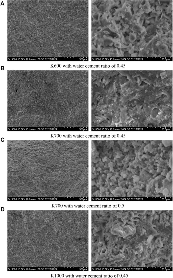
FIGURE 4. SEM of superfine cement test block.
Then observe the electron microscope scanning results of the test block of K700 superfine cement under the water-cement ratio of 0.45 and 0.5. It is not difficult to see that the micro-cracks of the test block have been improved, but from the high magnification of the interior, it becomes loose and porous as a whole, reducing the compactness of the test block and damaging its strength.
Through comprehensive comparison, it is found that K600 superfine cement has more large particles, K700 has a better average particle size distribution, and has better grading. Most K1000 superfine cement particles are of smaller particle size, which has more advantages in grouting micropores. However, with the increase in mesh size, the cost is also greatly increased, and the requirements for preservation are also higher, so K700 superfine cement has a higher cost-performance ratio. Increasing the mesh number of superfine cement can make hydration reaction better and produce stronger cementation. At the same time, micro-cracks and microbubbles will be generated due to water evaporation. Increasing the water-cement ratio will reduce the compactness of the microstructure, thereby affecting the macro strength of the test block.
Liquids naturally possess the ability to flow, and the fluidity of superfine cement has a significant impact on the strength after grouting. The amount of superfine cement grouting materials should be chosen based on the project’s real circumstances. Therefore, knowledge of the various rule governing the fluidity of superfine cement is essential if the fluidity of grouting materials used in real grouting is to meet the requisite requirement.
This experiment was conducted to assess the fluidity experiment of superfine cement with varied mesh numbers and different water-cement ratio, respectively, in order to examine the fluidity experiment of superfine cement. The net cement slurry was evaluated in a flowing mold in this experiment by combining varying quantities of superfine cement and water in a container, pouring the slurry into a truncated cone mold multiple times, and pounding it by lightly shaking and tapping the surface. After that, the cone is lifted vertically and the net cement slurry is no longer flowing in the glass plate, the maximum and minimum diameters are measured with a ruler, and the average value is taken as the superfine cement flow. The loading and measurement steps in the experiment can be seen in Figure 5.
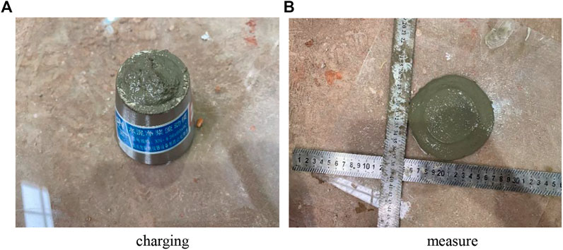
FIGURE 5. Fluidity model and fluidity measurement of cement paste.
In order to avoid the insufficient water requirement of the cement slurry to form a grouting liquid due to the too small particle size of the cement, the three kinds of superfine cements were tested in advance, which can also facilitate the comparison of the performance changes of the superfine cements with different meshes. In this experiment, K600 superfine cement water-cement ratio gradient is 0.35, 0.4, 0.45 and 0.5, K700 superfine cement water-cement ratio gradient is 0.4, 0.45, 0.5 and 0.55, K1000 superfine cement water-cement ratio gradient is 0.45, 0.5, 0.55 and 0.6. The fluidity data collected at various water-cement ratios are displayed in Table 4.
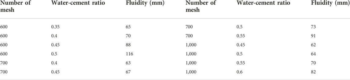
TABLE 4. Fluidity of superfine cement with different water cement ratio.
According to the fluidity ratio design and experimental method of cement paste, the fluidity of different mesh superfine cement under different water-cement ratio is tested, and the results are as follows.
Figure 6 shows that as the proportion of water in the cement slurry grows, so does the fluidity, and there is a critical point for the influence of the superfine cement water-cement ratio on fluidity. The water-cement ratio generates a considerable increase in fluidity beyond the crucial point, but the change before it is relatively small. However, comparing the fluidity change laws of three kinds of superfine cement with different mesh numbers, it can be seen that the superfine cement with higher mesh numbers can reduce the increase of fluidity after the critical point. The curve change laws of K700 and K1000 superfine cement are basically the same, and its fluidity change curve is more gentle, and the fluidity of K600 superfine cement will be greatly improved after the critical point. The fluidity of superfine cement with a higher mesh will be reduced and it will be more viscous under the same water-cement ratio (Guo et al., 2017). However, with the increase of the proportion of water in the cement paste, the change range of fluidity of superfine cement with higher mesh is also smaller.
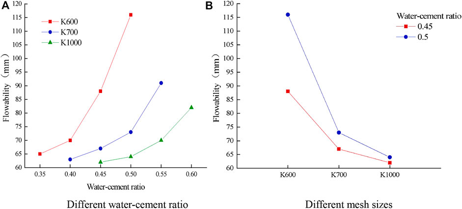
FIGURE 6. Superfine cement flow rate variation law.
The superfine cement particles will become more dispersed when the water content in the cement slurry rises, which will reduce slurry consistency and promote further diffusion. As a result, superfine cement fluidity rises as the water-cement ratio rises.
The superfine cement with a high mesh number will reduce the fluidity of cement slurry, but it can also control the fluidity of cement slurry more effectively (Zhou and Xu, 2016). This is because the particle size of superfine cement is refined, and the specific surface area is increased, which intensifies the hydration reaction. The reduction of free water also reduces the fluidity of its slurry. Moreover, due to the smaller distance between particles, it can produce greater force and have stronger cohesion. Therefore, it can more effectively control the fluidity change of cement paste and better reduce the error caused by the water-cement ratio in the process of cement mixing.
The initial setting time and final setting time of different mesh superfine cement under different water-cement ratio are tested by the Vicat apparatus. The results are as follows in Table 5.
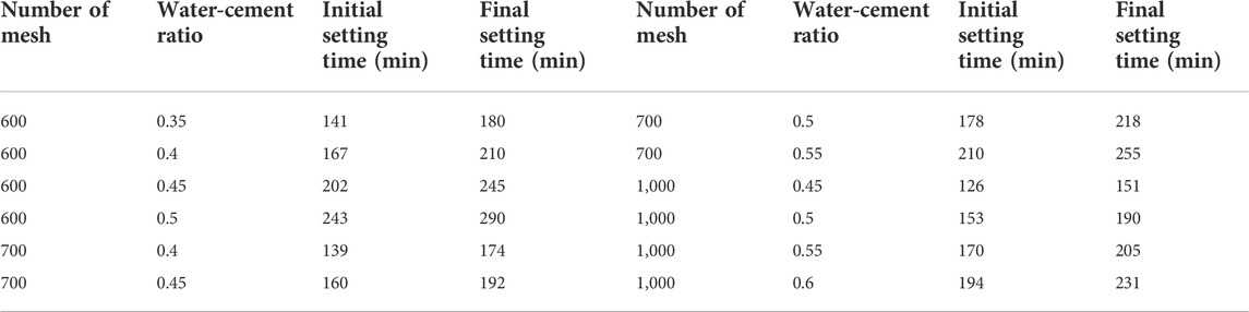
TABLE 5. Setting time of superfine cement with different water cement ratio.
Figure 7 depicts the varying trends for three distinct types of superfine cement at various water-cement ratios. The observation in Figure 7 shows that the initial setting time and final setting time of cement slurry steadily rise with an increase in the water-cement ratio. All three types of superfine cement have the same growth range, although those with greater mesh sizes build up more quickly.
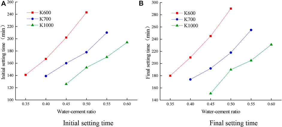
FIGURE 7. Setting time of superfine cement with different water-cement ratio.
When the water-cement ratio of the three kinds of superfine cement is the same and the numbers are all 0.45, it can be seen from Figure 8 that the initial setting time of K700 superfine cement is 42 min shorter than K600 superfine cement, and K1000 superfine cement is 34 min shorter than K700 superfine cement. The final setting time of K600, K700, and K1000 superfine cement is shortened by 53 min and 41 min, respectively. The calculation shows that the setting time is shortened by about 21%, so the increase in the mesh number of superfine cement can effectively reduce the initial and final setting time of cement slurry and shorten the setting time.
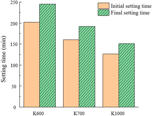
FIGURE 8. Comparison of setting time of superfine cement with different mesh numbers.
After the cement slurry has been configured for a while, the ratio of the percentage of the mass of water that is leaked out of the slurry to the percentage of the initial total mass of water used in the slurry is called the bleeding rate. The experiment first follows the experimental program configuration of cement slurry, and the slurry is filled into the container used for the experiment, after standing for a period of time with a rubber-tipped pipette to suck out the surface water, and injected into the measuring cylinder, until the slurry has no water analysis. The water is collected in the measuring cylinder to read and record, and the amount of water secretion is accurate to 1 g. See Figure 9 for details.
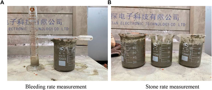
FIGURE 9. Stability experiment.
The calculation formula is as follows.
With: B -bleeding rate (%) accurate to 1%; m -water secretion amount (g); m0 -slurry water consumption (g); M -total mass of slurry (g); G -total mass of specimen (g).
The stone rate is configured according to a certain ratio of slurry. A steel ruler is used to measure and record the volume of the stone body after 100 ml of slurry is poured into a container and placed in the standard maintenance room for 24 h.
The stone rate is the ratio of the volume of the stone body to the total volume of the slurry, which is calculated according to the following formula:
With: B' -Cement slurry stone formation rate (%); Vs -volume of stone body (ml); V -Total volume of cement slurry (ml).
1) Experimental results of bleeding rate According to the proportioning scheme and experimental method of superfine cement bleeding rate, the bleeding rate of superfine cement with three mesh sizes under different water-cement ratios is shown in Table 6 below.
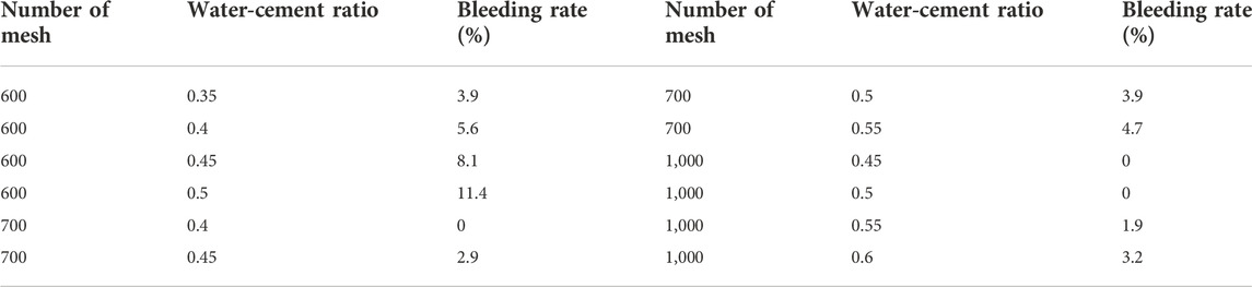
TABLE 6. Bleeding rate of superfine cement with different water-cement ratio.
Figure 10 shows that as the water-cement ratio increases, the bleeding rate of superfine cement increases. The water secretion situation for K600 cement is more serious than for K700 and K1000 cement, which is more obvious by the water-cement ratio. The latter two water retention situations are more advantageous. Comparing the change of water secretion rate of three kinds of superfine cement under the water-cement ratio of 0.45 and 0.5, there is no water precipitation from K1000 superfine cement, and the water secretion rate of K700 is only less than half of that of K600, which greatly reduces the water precipitation because the particle size of cement particles becomes smaller after refinement. And its specific surface area increases, allowing more free water to wrap around the cement particles and hold the water in the slurry, reducing water secretion.
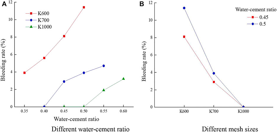
FIGURE 10. Variation law of bleeding rate of superfine cement.
2)Experimental results of stone rate According to the superfine cement bleeding rate proportioning scheme and experimental method, the water secretion rates of three grades of superfine cement in different water-cement ratio cases are as follows in Table 7.
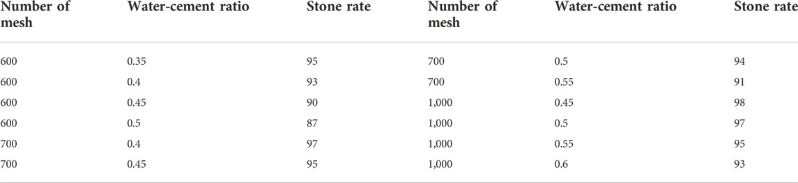
TABLE 7. Stone rate of superfine cement with different water-cement ratio.
It can be seen from Figure 11 that the stone rate of superfine cement with three mesh numbers shows a downward trend with the increase of water cement ratio. According to the change trend of water cement ratio K600 superfine cement has a large decrease, while K700 and K1000 superfine cement have little difference, slightly higher than K600. Figure 11 demonstrates that increasing the mesh of superfine cement can increase the stone formation rate of cement slurry and can also better cope with the influence of fluctuating water-cement ratio to minimize uneven mixing of slurry, resulting in uneven cementation solidification.
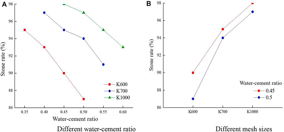
FIGURE 11. Variation law of stone rate of superfine cement.
Combined with the mobility and stability test results of superfine cement materials in the previous paper, this chapter of the experiments used in the preparation of stone systems follows the ratio program designed in Table 8. According to the design of different ratio programs, there will be a certain proportion of superfine cement mixed with water and mixed well. Using a cubic triplex compressive test module mold made of 7.07 cm × 7.07 cm × 7.07 cm standard test blocks, to be dismantled after the final set, each group of ratios prepares three test blocks. Figure 12 shows the process of cement slurry loading into the mold and the test piece prepared.

TABLE 8. Proportioning scheme of superfine cement stone.
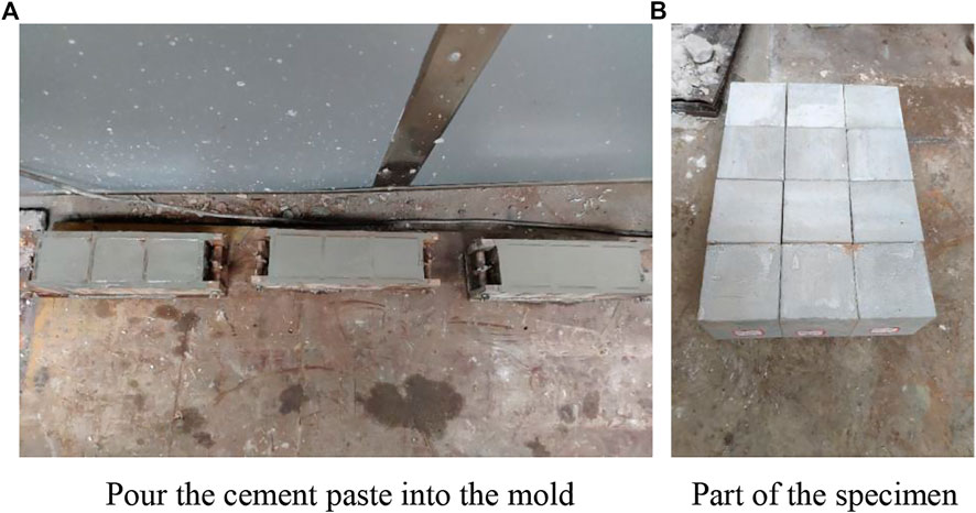
FIGURE 12. Preparation of stone specimen.
The uniaxial compressive strength test of the superfine cement aggregate was conducted in the form of axial compression by the RMT-150C rock mechanics test system, and the longitudinal and transverse strains of the specimens after compression were collected using the D3816N strain acquisition system during the experiment, as shown in Figure 13.
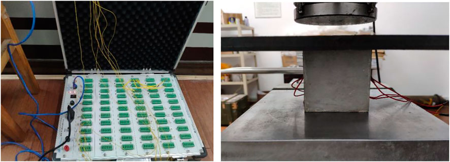
FIGURE 13. Strain acquisition system and uniaxial compression test.
According to the requirements of the rock mechanics test, the surface of the specimen needs to be polished smoothly with sandpaper before the loading test, and the actual dimensions are measured with vernier calipers. Wipe the surface with alcohol at the center of both sides of the specimen, and then use 502 glue to paste a 120-10AA resistance strain gauge horizontally and vertically at the center of both sides. Connect the strain gauge to the strain acquisition system with a cable, and wrap the connection with electrical insulation tape.
When formal loading, the top, and bottom of the specimen will be evenly coated with butter and placed in the center of the lower pressure table, after which the tester will begin pre-loading. Start the RMT test loading system and the strain test system at the same time when the pre-loading is finished to record the strain data. The uniaxial compressive test loading mode was selected as force-stroke controlled loading mode, and the loading rate was set to 0.5 kN/s until the specimen was destroyed due to the large strength of the pure cement specimen. The compressive strength of the same group of triple mold specimens was averaged at 0.01 MPa. The uniaxial compressive strength and elastic modulus of elasticity of 12 groups of specimens at early and late stages can be obtained from the calculation.
With: σc-Uniaxial compressive strength of stone body (MPa); P-Critical load of stone body damage (kN); A-Stone body cross-sectional area (cm2); ε-Elastic modulus (MPa); L0-Stone body original length (mm); L-Length of stone body after deformation (mm).
As shown in Table 9, the water-cement ratio is the biggest factor affecting the strength of superfine cement aggregate specimens, and the increase in the water-cement ratio leads to a very obvious reduction in specimen strength. The strength of superfine cement of different mesh numbers is affected by the water-cement ratio to varying degrees, with the percentage of strength reduction of superfine cement K600, K700, and K1000 being 26.2%, 23.1%, and 4.5%, respectively.
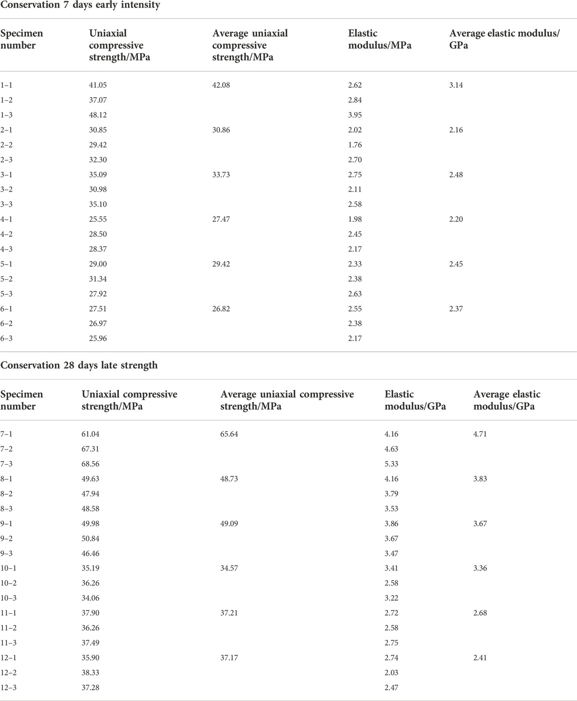
TABLE 9. Strength test results of stone specimen.
When the water-cement ratio remains constant, increasing the superfine cement mesh can improve the strength of stone body specimens, and the strength gain is more noticeable early on. The strength of K700 stone body specimens rose by 9.3% when compared to K600. The strength of the K1000 superfine cement stone body is 7.1% greater than that of K700, whereas the strength of K600 and K700 superfine cement specimens does not change considerably in the later stage, but the strength of K1000 aggregate is still 7.6% higher than that of K700 aggregate.
Then by comparing the early and late strengths of the stone specimens with the same mesh and water-cement ratio, it can be found that the early strength of K600 superfine cement specimens at 7 days of maintenance is only 64% of the late strength at 28 days of maintenance, while the early strengths of K700 and K1000 superfine cement reach 74.2% and 75.6% of the late strength respectively, which is not a big difference.
With the increase in the water-cement ratio, the elastic modulus will decrease accordingly, but the influence degree of superfine cement with different mesh is different. The gap between the early and late elastic modulus of superfine cement with high mesh will be smaller, and the influence degree of superfine cement with higher mesh will be lower. In the case of the same water-cement ratio in the early stage, the modulus of elasticity of superfine cement with a high mesh number will be improved, but in the later stage is instead a decreasing trend, indicating that the higher the mesh number of superfine cement can play a role in the better hydration reaction in the early stage, but in the later stage will be more easily deformed due to the evaporation of water resulting in fine bubbles or cracks in the cement.
As a result, as the cement mesh size grows, so does its strength, though the increase is not significant. The most significant benefit of reducing the particle size of superfine cement is that it has less impact on the fluctuation of the water-cement ratio in the cement slurry, allowing the concentration of the cement slurry to be better deployed to ensure strength stability, and the increased mesh size allows the hardened cement slurry to reach higher strength earlier and reach final stable strength faster. According to the market price of superfine cement with different mesh sizes displayed on a platform, the prices of K600, K700, and K1000 cement are 2,353.79 yuan/t, 2,700.83 yuan/t, and 3,051.94 yuan/t, respectively. Compared to the material and resources required for K1000 cement, K700 cement is a better balance of cost and efficiency improvement.
Through field investigation and data collection, the known conditions of the working face that needs grouting reinforcement in Shuiliandong Coal Mine are as follows: the working face is located between two goafs in the north of the mining area, and 6 m coal pillars are reserved between the goafs. The average thickness of the coal seam of the working face is 9.8 m. The cutting hole of the working face is located at its western boundary, connecting the return air chute in the south and the transportation chute in the north. The net width of the roadway is 5 m and the net height is 4 m. Through exploration, the thickness of the top and bottom coal of the return air chute in this working face has been found to be 9.6 m in total, among which the thickness of the roadway to be reinforced by grouting in the broken abnormal zone has been reduced to 5.3 m. According to the analysis of the geological exploration drilling data, the lithology, thickness and fissure development of the roof and floor are shown in the following Table 10.
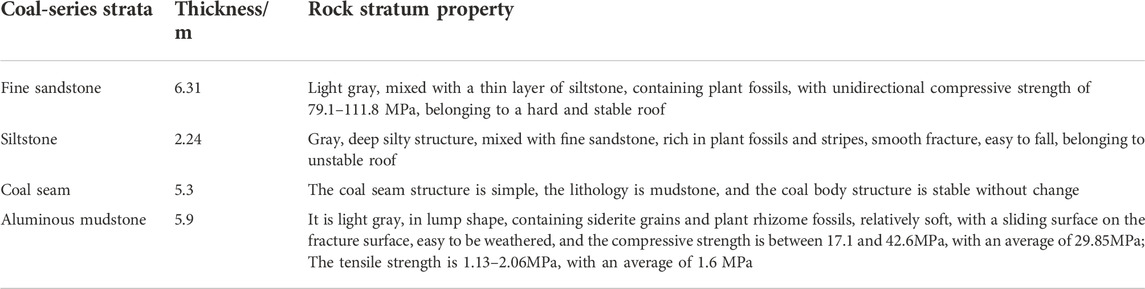
TABLE 10. Top and bottom slate.
To prevent the surrounding rock of the roadway from deforming during the mining process of the working face, leading to safety accidents, the roadway needs to be supported and reinforced. At present, the combined support of an anchor mesh belt and anchor cable reinforcement is used. The roadway is a full section of shotcrete. According to the data from the previous indoor experiment, K700 superfine cement with a water-cement ratio of 0.45 is used for on-site grouting reinforcement. This grouting and reinforcement adopt split grouting. The surrounding rock mass needs to be damaged before filling and grouting. The required pressure is large, belonging to high-pressure grouting. Therefore, the initial pressure in this grouting is not more than 6MPa, and the final pressure is 10 MPa.
To compare the deformation and damage of the roadway in the grouting section and the non-grouting section, monitoring section a is set at 100 m ahead of the work face, and monitoring section b is set at 30 m ahead. Monitoring sections a and b are used to monitor the displacement of the roof and floor and the two sides of the grouting section. Monitoring sections c and d are respectively set at 30m and 60 m from the monitoring section to monitor the deformation of the roadway in the un-grouting section. See Figure 14 for details.
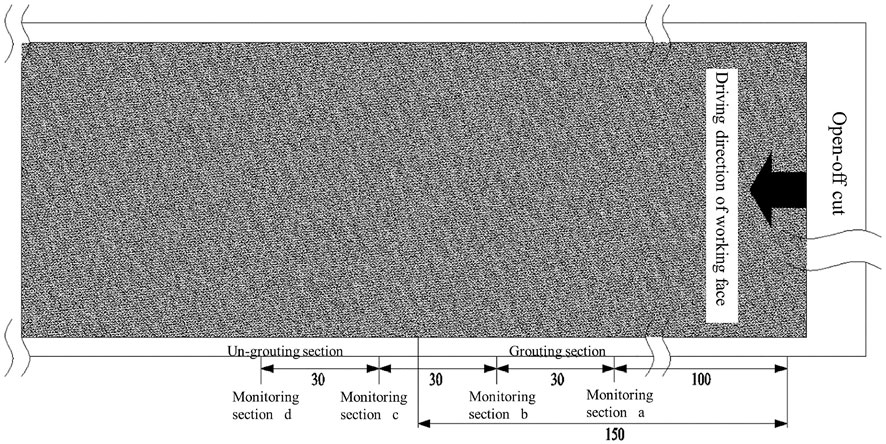
FIGURE 14. Roadway monitoring cross-section arrangement.
When the mining of the working face starts, sections a, b, c, and d will be monitored. With the advancing distance of the working face, the deformation and displacement of the roadway will be recorded. The monitoring displacement curve is as follows.
From Figure 15, it can be seen that with the advance of the working face, the roof and floor of the roadway in the un-grouting section are significantly deformed, and the settlement and bottom heave are serious, with a displacement of about 1.5 m. The monitoring data of sections c and d show that the surrounding rock condition of the roadway has been improved after grouting reinforcement. The displacement of the roof and floor is about 0.5m, and the deformation and damage are not obvious.
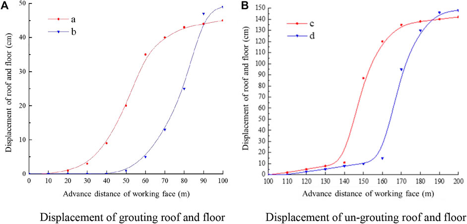
FIGURE 15. Proximity of the roof and floor of monitoring section.
Similarly, based on the displacement monitoring data of the two sides of the roadway, the inhibition effect of grouting reinforcement on the deformation of the surrounding rock of the roadway can be demonstrated. As can be seen from Figure 16, under the influence of high ground stress and strong mining, the displacement of the two sides of the monitoring section reaches 0.8m, and the deformation of the two sides is large and broken, even leading to the breakage and failure of the anchor bolt mesh. After the grouting reinforcement of the roadway, the displacement of the two sides is greatly reduced, It is about 0.3m, and the reinforcement effect is significant.
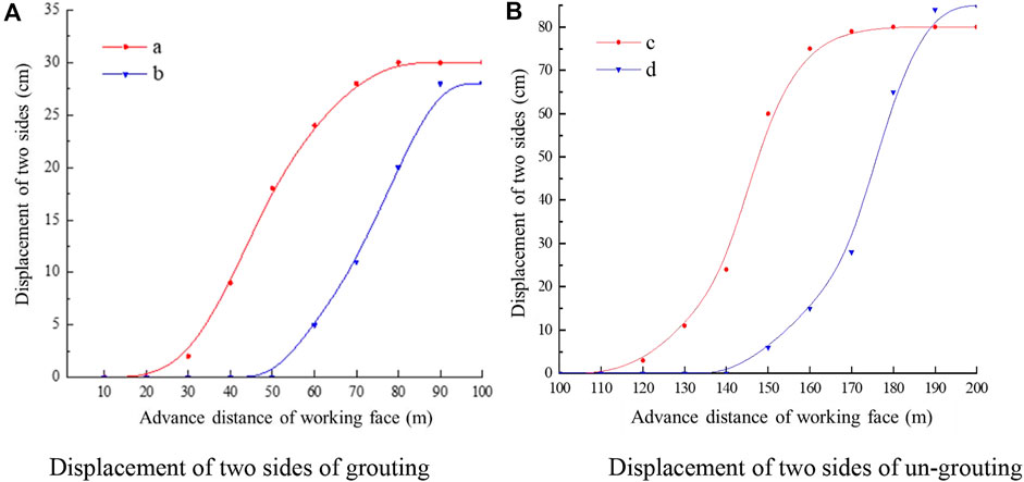
FIGURE 16. Monitoring the amount of migration on both sides of the section.
Through the comparison of the test sections, the results show that the overall strength of the surrounding rock of the roadway is increased after grouting reinforcement, which effectively controls the occurrence of large deformation and damage to the surrounding rock, improves the stability of the surrounding rock, and meets the requirements of its long service life.
This paper investigates the fundamental performance characteristics of K600, K700, and K1000 superfine cement with various particle sizes through experiments and theoretical analysis, and thoroughly considers the fluidity, stability, and stone mechanical properties of the three mesh superfine cement under the influence of water-cement ratio. It then comes to the main conclusions listed below.
1) The large particle size of K600 superfine cement is larger, whereas K700 has a significantly smaller large particle size and excellent gradation. K1000 superfine cement is a small-size cement particle basically, but there are still larger-size cement particles and higher requirements for the storage environment.
2) The water-cement ratio is the biggest factor affecting the flow stability of superfine cement slurry. The flow of the refined cement slurry will be reduced, but at the same time, the effect of the water-cement ratio on the flow can also be reduced. High-mesh superfine cement takes less time to set, and the reduction ratio is about 21%. K600 cement water secretion is more serious compared with K700 and K1000 and is more obviously affected by the water-cement ratio. The high mesh count of superfine cement can improve the stone formation rate of superfine cement slurry and also better cope with the fluctuating influence of the water-cement ratio. Increasing the mesh count of superfine cement can effectively enhance the stability of superfine cement grouting material.
3) At the same water cement ratio, the strength of high mesh superfine cement stone specimens is higher, especially in the early stage. Meanwhile, increasing the mesh number allows the hardened cement slurry to reach the final stable strength faster. The modulus of elasticity of superfine cement agglomerates with high mesh number increases in the early stage but shows a decreasing trend in the later stage instead.
4) K700 superfine cement was used to grout the roadway. According to the monitoring data of grouting and non-grouting sections, it was found that the overall strength of the surrounding rock after grouting was improved, and the bearing capacity was significantly enhanced. Using K700 superfine cement grouting can effectively reduce the impact of geostress on the surrounding rock of the roadway, inhibit the deformation and destruction of the surrounding rock, and improve its stability.
The raw data supporting the conclusion of this article will be made available by the authors, without undue reservation.
WY completed the research design and revised the manuscript. XW and QG completed the experiment and collected the experimental data. WY and MZ analyzed the data and completed the writing of the paper. All authors read and approved the final manuscript.
This work was supported by the National Natural Science Foundation of China (Nos. 51974117, 52174076), Hunan Natural Science Foundation Project (No. 2020JJ4027).
In addition, we would like to thank the anonymous reviewers who have helped to improve the paper.
The authors declare that the research was conducted in the absence of any commercial or financial relationships that could be construed as a potential conflict of interest.
All claims expressed in this article are solely those of the authors and do not necessarily represent those of their affiliated organizations, or those of the publisher, the editors and the reviewers. Any product that may be evaluated in this article, or claim that may be made by its manufacturer, is not guaranteed or endorsed by the publisher.
Chen, M. X. (1998). Development status and application of ultrafine cement grouting materials. Cem (11), 9–11. doi:10.13739/j.cnki.cn11-1899/tq.1998.11.003
Chen, X., N., and Gu, S. C. (1999). Grouting material of finy or superfine cement and its function. J. Xi’an. Univ. Sci. Techno. 19 (S1), 91–94. doi:10.13800/j.cnki.xakjdxxb.1999.s1.024
Feng, Z. Q., Kang, H. P., and Han, G. Q. (2013). Polyurethane grouting materials modified by inorganic salts in coal mines. Chin. J. Geot. Eng. 35 (08), 1559–1564.
Guan, X. M., Hu, S. G., and Ding, Q. J. (2003). Study on the performance of superfine high performance grouting cement and its microstructure. Cem (6), 10–13. doi:10.13739/j.cnki.cn11-1899/tq.2003.06.003
Guan, X. M., Zhang, H. B., and Yang, Z. P. (2020). Research of high performance inorganic-organic composite grouting materials. J. China. Coal. Soc. 45 (3), 902–910. doi:10.13225/j.cnki.jccs.SJ20.0117
Guo, D. M., Tan, J. X., and Xiao, Z. X. (2017). Study on the optimum proportion and grouting effect of superfine cement slurry. J. Henan. Univ. Sci. Techno Nat. Sci. Ed. 36 (5), 001–008. doi:10.16186/j.cnki.1673-9787.2017.05.001
Jiang, Y., Guo, F., and Kong, H. (2020). Preparation and properties of acrylate-cement grouting composite. New. Build. Mat. 47 (08), 159–163. doi:10.3969/j.issn.1001-702X.2020.08.037
Li, Y. X., and Chen, Y. M. (2006). Influence ground mineral admixtures on pore structure of hardened cement paste and strength of cement mortar. J. Chin. Ceram. Soc. 34 (05), 575–579. doi:10.14062/j.issn.0454-5648.2006.05.013
Perret, S., Palardy, D., and Ballivy, G. (2000). Rheological behavior and setting time of microfine cement-based grouts. ACI. Mat. J. 97 (4), 472–478.
Yan, G. C., Bai, L. J., and Zhang, Z. Q. (2020). Experimental and applied study on PU modified sulpho-aluminate cement grouting material. J. China. Coal. Soc. 45 (S2), 747–754. doi:10.13225/j.cnki.jccs.2020.0248
Yang, H. L. (2019). Deformation and reinforcement mechanism of fractured rock mass under grouting and its application. Jinan: Shandong. Univ.
Yu, W. J., Li, K., and Lu, Q. (2021). Engineering characteristics and deformation control of roadways in fractured rock mass. J. China. Coal. Soc. 46 (11), 3408–3418. doi:10.13225/j.cnki.jccs.2020.2029
Yu, W. J., Li, K., and Zhang, J. (2020). Deformation characteristics and control factors of the surrounding rock in the deep buried soft rock roadway under the influence of mining. Coal. Sci. Techno. 48 (01), 125–135. doi:10.13199/j.cnki.cst.2020.01.016
Yu, W. J., Wan, X., and Liu, F. F. (2021). Experimental study on red clay paste backfilling material and its physical characteristics. Coal. Sci. Techno. 49 (2), 61–68. doi:10.13199/j.cnki.cst.2021.02.008
Yu, W. J., Wu, G. S., and An, B. F. (2019). Large deformation characteristics and stability control of roadway with fractured rock mass. J. Min. S. Eng. 36 (01), 103–111. doi:10.13545/j.cnki.jmse.2019.01.015
Zhang, N., Hou, C., and Chen, Q. (1998a). Grouting plus solids performance experiments on roadway perimeter rock. J. LiaoNing. Tech. Univ. (01), 15–18.
Zhang, N., Hou, C., and Chen, Q. (1998b). Mechanical properties of the grouted consolidated body after rock destruction. Rock. Soil. Mech. (03), 50–539. doi:10.16285/j.rsm.1998.03.009
Zhang, Y. Q. (2010). Micro-experimental study and theoretical analysis on permeability of micro-fine cement. Qingdao: Shandong Univ. Sci. Techno.
Zhao, Q., Zhang, Y. X., and Zhao, J. (2020). Study on the preparation and performance of cement-based grouting material with quick setting and water resistance. J. Funct. Mat. 51 (06), 6114–6119+6157. doi:10.3969/j.issn.1001-9731.2020.06.019
Keywords: grout reinforcement, superfine cement, particle size proportioning, fluidity, stability, uniaxial compressive strength
Citation: Yu W, Zhou M, Wan X and Guan Q (2022) Experimental study on physical properties of superfine cement grouting material. Front. Mater. 9:1056135. doi: 10.3389/fmats.2022.1056135
Received: 28 September 2022; Accepted: 17 November 2022;
Published: 07 December 2022.
Edited by:
Marcello Vasta, University of Studies G. d'Annunzio Chieti and Pescara, ItalyReviewed by:
Zhongsheng Tan, Beijing Jiaotong University, ChinaCopyright © 2022 Yu, Zhou, Wan and Guan. This is an open-access article distributed under the terms of the Creative Commons Attribution License (CC BY). The use, distribution or reproduction in other forums is permitted, provided the original author(s) and the copyright owner(s) are credited and that the original publication in this journal is cited, in accordance with accepted academic practice. No use, distribution or reproduction is permitted which does not comply with these terms.
*Correspondence: Mingjuan Zhou, MjU4MDM3NjUyMUBxcS5jb20=
Disclaimer: All claims expressed in this article are solely those of the authors and do not necessarily represent those of their affiliated organizations, or those of the publisher, the editors and the reviewers. Any product that may be evaluated in this article or claim that may be made by its manufacturer is not guaranteed or endorsed by the publisher.
Research integrity at Frontiers
Learn more about the work of our research integrity team to safeguard the quality of each article we publish.