 Yan Xu
 Hongwei Li1
 Hua Li
- 1School of Aeronautics and Astronautics, Zhejiang University, Hangzhou, Zhejiang, China
- 2Beijing Institute of Space Mechanics & Electricity, Beijing, China
- 3Laboratory of Aerospace Entry, Descent and Landing Technology CASC, Beijing, China
A fully 3D-printed soft pneumatic robotic arm based on two types of gas-structure coupling actuators is designed for on-orbit servicing. The path planning algorithm and trajectory tracking control strategy of the arm are developed. A model-free closed-loop control system with a PID controller and an iterative learning controller is built to improve the performance speed for repeated tasks. An experiential knowledge database for an iterative learning controller is described. The effectiveness of the iterative learning controller is verified by comparative experiments. The obstacle avoidance path planning algorithm based on the A* algorithm is presented. The validity of the path planning algorithm and trajectory tracking control strategy are verified by obstacle avoidance path planning experiments. The experimental results show that intelligent motion control and obstacle avoidance of the fully 3D-printed soft robotic arms are realized within an acceptable error.
1 Introduction
In recent years, space robot technology has attracted increasing attention. Space robots play an important role in realizing on-orbit servicing, such as on-orbit maintenance of spacecrafts (Shi et al., 2022), on-orbit capture of space debris, and on-orbit construction and maintenance of space stations (Post et al., 2021). To avoid ultrahigh-speed collisions between space debris and the spacecraft, space robots can be used to capture space debris. Traditional rigid capture robots represented by the Canadian arm have been used for a long time. Traditional flexible capture robot systems include flying nets (Riccardo et al., 2016), harpoons (Reintsema et al., 2010), flying claws (Reed et al., 2012), thin-film sails, and magnetic cables. With the development of bionics and advanced manufacturing technology for soft materials, soft robots have attracted the attention of many researchers. Compared with traditional rigid robots, soft robots have the advantages of strong environmental adaptability, high safety, more freedom and low cost. Soft robotic arms (SRA) are research hotspots in the soft robot field and are expected to be widely used in space robots (Nishioka et al., 2017; Chen et al., 2018).
The SRA are challenging to control due to their highly nonlinear hysteresis characteristics, uncertainties and sensitivity to external loading history. The SRA can realize the shape control (Zhang et al., 2016) and the internal pressure control of the pneumatic chambers (Huang et al., 2018). Many research works have been done on position and attitude control using classical control algorithms (Marchese et al., 2016; Hao et al., 2017; Santoso et al., 2017; Alaa et al., 2018). Recently some new intelligent control algorithms were adopted. A dynamic model of the SRA is identified using a system identification procedure with iterative learning control to improve the tracking performance (Hofer et al., 2018; Hofer et al., 2019). Satheeshbabu have trained a reinforcement learning control policy based on the deep deterministic policy gradient (DDPG) for path tracking (Satheeshbabu et al., 2020). Shakiba et al. have modelled the hysteresis of a miniature pneumatic artificial muscle-based catheter and proposed a feedforward controller (Shakiba et al., 2021). These research works focus on establishing mechanical models and control strategies based on these models. However, there will be inevitable errors and uncertainties in the models of the SRA due to highly nonlinear hysteresis characteristics and sensitivity to external loading history (Chu et al., 2020; Chen et al., 2021). This will require the properties and parameters in the models to be identified and modified periodically, making the control of the SRA very difficult. It is necessary to develop control strategies without these mechanical models.
Space soft robots that work on complex tasks such as on-orbit servicing are controlled to reach an end goal and avoid collision with a variety of obstacles. The SRA requires sophisticated path planning algorithms and obstacle avoidance in the workspace. Path planning of the SRA remains a real scientific challenge and there are only few studies that address path planning with obstacle avoidance of the SRA. For instance, a novel, efficient path planning algorithm has been proposed to efficiently accommodate multiple curve-like obstacles for a soft robotic arm (Fairchild et al., 2021). The arm is described by a 3-segment constant curvature model and the method is tested in a simulation with multiple settings for the obstacles. A kinematics model of a mobile soft arm has been proposed using polynomial PH quintic curve theory and a curvature control algorithm with simultaneous obstacle avoidance based on potential field of velocity was suggested (Mbakop et al., 2020). The algorithm is based on the principle of sliding mode, which ensures a finite time convergence. However, traditional approaches to kinematics and control for soft robots do often not consider the robot’s entire shape or envelope, which limit the capacity of the SRA to take full advantage of its inherent compliance (Marchese et al., 2014).
In the preliminary work, a control strategy based on PID controller was proposed for a fully 3D-printed soft pneumatic robotic arm based on hexagonal origami (Li et al., 2022). But the performance speed of the SRA’s end approaching the target point is slow. To solve this problem, a model-free control strategy which includes PID controller and iterative learning controller is proposed in this paper. The obstacle avoidance path planning algorithm based on the A* algorithm and PID control strategy is presented. Simulation and experiments are carried out to show the effectiveness and superior performance of the proposed algorithms. The remainder of this paper is organized as follows: The design of the SRA based on two types of gas-structure coupling actuators is presented, and the work space of the SRA is verified using the nonlinear finite element method in Section 2. A closed-loop model-free control strategy based on PID controller and iterative learning controller is outlined in Section 3. The obstacle avoidance trajectory planning of SRA is proposed and is verified by the test in Section 4. Finally, Section 5 summarizes a few concluding remarks and suggestions for future work.
2 Fully 3D-printed soft robotic arm
2.1 Conceptual design of soft space capture robot
To satisfy the functional requirements of flexible capture for noncooperative targets, a soft capture robot that consists of extensible and bendable gas-structure coupling actuators are presented. The soft space capture robot includes two pneumatic extensible actuators (PEA1 and PEA2), a pneumatic bendable actuator (PBA), end capture actuators, as well as gas supply and control systems, as shown in Figure1. Compared with existing rigid and flexible capture systems, the robots can be packaged into a small volume and have the following advantages: a large task space, a high load-mass ratio, low power consumption, low fabrication cost and the ability to achieve high-speed operation. Compared with existing soft robotic arm (Gong et al., 2016), the bending and stretching motion are independent and implemented by separate actuators in the robots, which making motion control easier to achieve. While the existing theory and algorithms of traditional manipulators can be transplanted into this robot more easily.
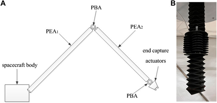
FIGURE 1. Soft space capture robot and soft robotic arm. (A) Soft capture robot. (B) Soft robotic arm.
The main types of actuators in the soft space capture robots are pneumatic extensible actuators, pneumatic bendable actuators and end capture actuators. The end capture actuators need to be specially designed for different capture tasks. Soft robotic arms, including pneumatic extensible actuators and pneumatic bendable actuators, are investigated in this paper. These types of gas-structure coupling actuators stretch or bend greatly under gas pressure, and the large structural deformation changes the gas state. The strong gas-structure coupling effect makes the mechanics modeling and control of the SRA very difficult.
The SRA must be packaged into a small volume when it is launched; therefore, the pneumatic extensible actuators must have small initial lengths and large linear extensible strokes. The structural concept of the pneumatic extensible actuators is shown in Figure 2, including the main body, gas-tight layer, flexible thermal protection layer, endplates and gas inlet. The main body of the actuators is made of hyperelastic soft material. The actuators can realize axial elongation under inflation pressure and the self-folding process is suitable to be completed by releasing the elastic potential energy of the hypersonic material. The actuators also expand radially. But the radial deformation is not obvious when inflation pressure is not high. The initial configuration of the main body is designed based on a hexagonal origami pattern and is fabricated using 3D printing technology. To adapt to the thermal environment of the space, laminated aluminium films are used to form a flexible thermal protection layer on the outer wall of the main body and Kapton film is adhered to the inner wall as a gas-tight layer. As shown in Figure 2, the flexible thermal protection layer and the gas-tight layer can adhere to the mountain lines of hexagonal origami. Between the two bonding positions, the two layers are separated from the main body of the actuators. Since the flexible thermal protection layer and gas-tight layer have little influence on the driving mechanism and load capacity of soft robotic arm, the following research focuses only on the main body of PEA and the prototype shown in Figure 1B does not include these two layers.
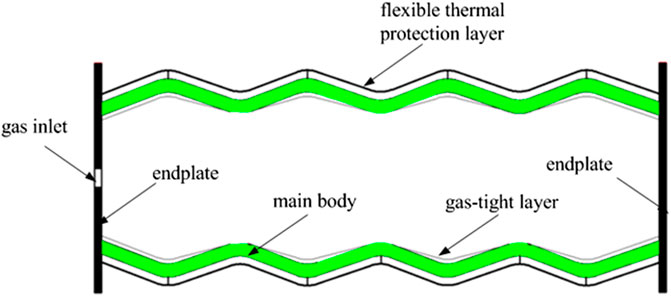
FIGURE 2. Pneumatic extensible actuator.
The pneumatic bendable actuators of the SRA need to achieve the bending motion process of two degrees of freedom. The actuators consist of four pneumatic bellows (B1- B4) and two nylon plates. The pneumatic bellows are fabricated by hyperelastic soft materials and 3D printing technology. Several pneumatic bellows are connected in parallel to form the pneumatic bendable actuators, as shown in Figure 3. The actuators are composed mainly of silicon rubber, except for the nylon plates, and are actuated by inflatable gas channels. The X-axis of the local coordinate system of the actuators is set to Lines B4 and B2, and the Y-axis is set to Lines B1 and B3. By controlling the pressure in the corresponding pneumatic bellows, a bending drive of two degrees of freedom can be achieved.
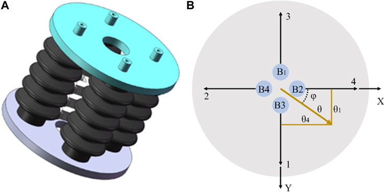
FIGURE 3. Pneumatic bendable actuator. (A) 3D model. (B) Local coordinate system.
The SRA is actuated by controlling the positive pressure between the inside and outside of the chambers, ensuring the feasibility of the SRA working either in space or within a vacuum environment. More specifically, before the SRA is sent into orbit, it will be vacuumed to be in a folded state, and a gas compressor supplying the inflatable gas should accompany it. Then, the SRA can operate in orbit by controlling the positive pressure in the chambers.
2.2 Work space analysis
Using the nonlinear finite element method, the work space of the SRA is analyzed. A finite element model is established in ABAQUS software and motion ability is simulated, as shown in Figure 4. The neo-Hookean model is used to describe the hyperelastic material. The driving pressures in the chambers of PEA1 and PEA2 are set to 20 kPa. Figure 4A–D correspond to the SRA movement in four quadrants respectively. The deformation configuration is shown in Figure 4A, while 20 kPa pressure is applied to the chambers of bellows B3 and B4. The deformation configuration is shown in Figure 4B, while 20 kPa pressure is applied to the chambers of bellows B2 and B3. The deformation configuration is shown in Figure 4C, while 20 kPa pressure is applied to the chambers of bellows B1 and B2. The deformation configuration is shown in Figure 4D, while 20 kPa pressure is applied to the chambers of bellows B1 and B4. The simulation results show that the six chambers can be inflated independently, and the SRA can achieve the combined motions of elongation, contraction and bending.
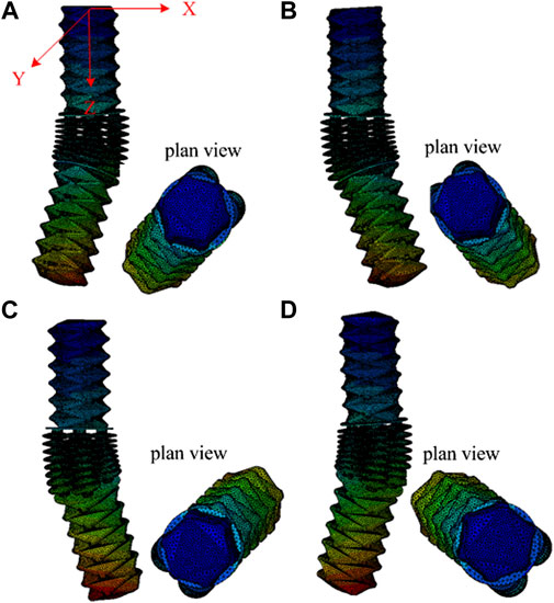
FIGURE 4. Simulation results of motion ability. (A) Move to first quadrant. (B) Move to second quadrant. (C) Move to third quadrant. (D) Move to fourth quadrant.
By nonlinear finite element analysis and kinematic analysis of the SRA, the work space of the SRA under positive pressure can be obtained, as shown in Figure 5A. The maximum coordinate ranges of the work space are: X: −202∼202 mm; Y: −202∼202 mm; Z: 574–990 mm. If positive pressure and negative pressure are adopted to drive the SRA, the working space can become larger, as shown in Figure 5B. The maximum coordinate ranges of the work space are: X: −350∼350 mm; Y: −350∼350 mm; Z: 162–990 mm.
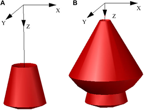
FIGURE 5. Work spaces of the SRA. (A) Work space under positive pressure. (B) Work space under positive and negative pressure.
3 Intelligent control strategy
3.1 PID + iterative learning controller
A model-free closed-loop control system based on a PID controller was used to control the coordinates of the SRA’s end (Li et al., 2022). However, the control system has a weight problem between response speed and overshoot. If a faster response speed is needed, the proportional term coefficient
A new closed-loop model-free control system based on a PID controller and iterative learning controller is developed to control the SRA’s end reaching from the current position
1) The target point
2) The quadrant of the local coordinate system for pneumatic bendable actuators in which the target point
3) The positive pressures in these chambers are determined to be controlled;
4) The corresponding bellows and SEA1&2 are controlled to derive the SRA’s end
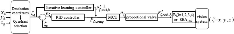
FIGURE 6. Closed-loop control system based on PID+iterative learning controller.
For example, in step 3, if the target point falls in the second quadrants in Figure 3B, the PID controller corresponding to B4 works to drive
In the control system shown in Figure 6, three independent controllers are set in the x, y, and z directions to control the motions accordingly. These controllers will work independently to eliminate position errors in the corresponding directions. For example, if
The PID + iterative learning controller is used to determine the compensation of the inflatable pressures
where
In Eqn. 1, a large coordinate deviation
The microcontroller unit (MCU) can control the output pressure of the proportional valves to the chambers by means of an analogue-to-digital converter (ADC). According to user manuals of the proportional valve (ITV 2050-312L, SMC Inc., Japan), there is
where
The output pressures of the proportional valves
where
The initial output pressures
Since the initial position and the expected position have the same coordination, the output of the PID controller is the same as the previous t-1 time when the repeated task is executed at time t. However, the total output
where
3.2 Experiential knowledge database
The history control information of the tasks that have already been executed can be directly used for the iterative learning controller when the tasks need to be re-executed. For a new task, the task can be repeated several times, so that the history control information is recorded for “learning”. For the SRA, repeated execution of the tasks each time leads to inefficiency even if it does not take much time. Therefore, an experiential knowledge database can be prepared for the SRA.
From analysis results in Section 2.2, the work space of the SRA in this paper is approximately X: −202∼202 mm; Y: −202∼202 mm; Z: 574∼990 mm. If the work space is meshed with intervals of 1 cm, there are 40 × 40 × 42 = 67200 “knowledge points”. The database can be constructed by repeating the task 30 times for each “knowledge point” and recording the control information from the last time. In the actual task, the coordinate unit of the target point is in mm, so it may not coincide with the above “knowledge point”. However, the historical control information of the nearest “knowledge point” can be selected as the input of the iterative learning controller. For example, if the coordinate of the task point is (111,98,733), then the “knowledge point” (110,100,730) can be selected as the input. For the SRA, each “knowledge point” needs a file to record the control information of the last task. The file needs to record the control information of the first 10 s (the PID controller mainly plays a role in maintaining terminal stability and eliminating steady-state error after 10 s). The control frequency of the SRA is approximately 5 Hz, and the control information of each control step is the output pressure of the five chambers. Each output pressure can be recorded using unsigned short data type (2 bytes), so the disk storage space required for the database to build the “knowledge base” is 32.04 MB (=67200 × 10 × 5 x 5 × 2 bytes).
3.3 Control test
To verify the aforementioned control system, an experimental platform for the SRA has been set up (Li et al., 2022). An SRA prototype is fixed to a grounded frame by means of a threaded connection on the upper end of PEA1, containing a small yellow ball on the SRA’s end, allowing the external camera system to record its position. The SRA’s end is controlled to move from the initial point (0, 0, 604) to the target point (100, 110, 670). The task was repeated 30 times, and the motion process of the first time and the 30th time are compared, as shown in Figure 7.
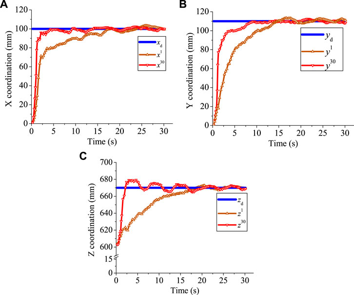
FIGURE 7. Experimental results. (A) X coordination. (B) Y coordination. (C) Z coordination.
In Figure 7,
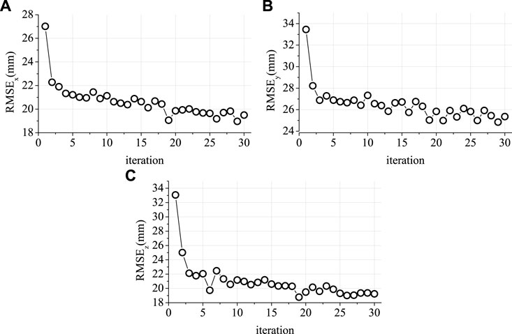
FIGURE 8. RMSE tracking errors. (A) RMSE in X coordination. (B) RMSE in Y coordination. (C) RMSE in Z coordination.
4 Trajectory tracking control
4.1 Obstacle avoidance path planning
The A* algorithm is adopted to realize obstacle avoidance trajectory planning of the SRA. The basic working principle of the algorithm is as follows: The work space of the SRA is discretized into a series of points, where each point has a corresponding “distance value” relative to the initial point. The initial point is defined as the starting point of the first motion step. There are eight neighboring points close to the starting point. The neighboring point that has the smallest “distance value” and has not been traversed so far is selected as the starting point of the next motion step. The path search process is completed successfully when the starting point of the next motion step is the goal point. Then, the path with the smallest “distance value” from the initial point to the goal point is planned. This algorithm is shown in Figure 9. The initial parent point is the initial point. The initial open set and closed set are empty sets.
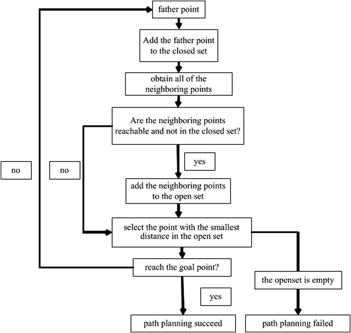
FIGURE 9. A* algorithm.
If the SRA’s end reaches a spatial point that makes it collide with the obstacles, this point is marked as unreachable. The criteria for the collision between the SRA and the obstacles are written as:
where
According to Eqn. 5, if the spatial point falls inside the obstacles or if the SRA’s end reaches a spatial point will make
Then, the central axes equation of the PEA1 and PEA2 are obtained. Finally, Eqn. 5 is used to determine whether the SRA and the obstacle collide by spatial position equations. Because PEA1 and PEA2 are cylinder-like objects, there may be collision between the actuators and the obstacle even though their central axes do not intersect. Therefore, a method for expanding
The points in the “closed set” are the points that have already been traversed and do not need to be traversed again, to avoid the self-locking phenomenon of the algorithm. The points in the “open set” are the points to be selected, and a point with the minimum distance value
where
The Euclidean distance
Combined with Figure 9 and Eqn. 7, it can be seen that the point at which the “distance value” is minimum from the “open set” is coarsely selected as the next parent point by the algorithm. Therefore, it can ensure that the path planned until reaching the goal point is the path with the smallest “distance value”. If the “open set” is empty before reaching the goal point, the algorithm cannot continue to update the parent point. In this case, there is no reasonable path to avoid obstacles, so the path planning process fails.
4.2 Trajectory tracking control strategy
Finally, the trajectory tracking control process of the SRA is described as follows:
1) The starting point and the goal point are defined and verified such that the points reside in the work space;
2) The obstacles of various shapes are simplified into cuboids, and the alert region is defined;
3) The obstacle avoidance trajectory is planned, and the coordinates of each point on the trajectory are saved in sequence;
4) The SRA’s end is controlled to move toward the target point by the PID controller;
5) Steps 4 are repeated until the target point reaches the goal point of the trajectory.
4.3 Simulation and experiments
4.3.1 Simulation of path planning
The effectiveness of the obstacle avoidance path planning algorithm is verified by a MATLAB code. First, the starting point of the SRA’s end is set as (0, 130, 710), and the goal point is set as (130, 0, 730). A cuboid obstacle is placed in the work space. The eight vertices of the cuboid obstacle are at (35, 40, 650), (140, 40, 650), (140, 40, 780), (35, 40, 780), (35, 140, 650), (140, 140, 650), (140, 140, 780), and (35, 140, 780). As shown in Figure 10, the brown cuboid represents the obstacle, and the black path identifies the effective obstacle avoidance path calculated by the code. The path planning algorithm continuously selects and excludes the points in the “open set” to explore the environment, and finally, an obstacle avoidance path with the minimum value of
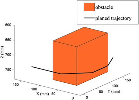
FIGURE 10. Simulation result of path planning.
4.3.2 Experiment of path planning
The obstacle avoidance path planning algorithm is verified by experiments. Since the obstacle avoidance path has been simulated, the obstacle avoidance experiment can be completed by controlling the SRA to track the obstacle avoidance path through the motion control system. The starting point and the goal point of SRA are set to be the same as those in the simulation. The space occupied by the obstacle is also the same. The SRA’s end is controlled to move from the starting point to the goal point. The external camera system is used to record the trajectory of small yellow ball on the SRA’s end.
The experimental results of path planning are shown in Figure 11. Figure 11A shows the SRA’s end moves from the starting point, passes the obstacles and finally reaches the goal point. The comparison between the simulation path and the test record is shown in Figures 11B,C. It can be seen that there is a small oscillation during the test where xe and ye are both close to 0 (the corner of the trajectory). The reason for this phenomenon is the stiffness of the four bellows at low chamber pressure and the “dead zone” of the proportional valves at 0–4 kPa. The expanded volume
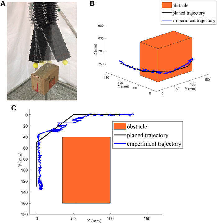
FIGURE 11. Experimental results of path planning. (A) obstacle avoidance path planning experiment. (B) comparison between the simulation path and the test record. (C) Top view of (B).
The change curve of the distance between the SRA’s end and the obstacle surface versus time is shown in Figure 12. The blue line is the border of the alert region. The black line is the planned trajectory, and the red line is the experimental trajectory. In the experiment, the SRA’s end basically moves according to the planned trajectory with an error smaller than 5 mm. The SRA’s end entered the alert region of the obstacle during 20–25 s, and there was no contact with the obstacle. The control algorithm adopted the repulsive effect to keep the SRA’s end out of the alert region. After bypassing the edge of the obstacle, the SRA’s end can quickly escape from the alert region and move according to the planned trajectory again. When the alert region is set for the obstacle, the expanding distances should not be too small to be able to produce a considerable repulsive effect in time. However, expanding distances that are too large may lead to path planning failure.
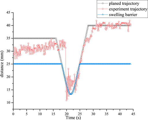
FIGURE 12. Change curve of the distance between the SRA’s end and the obstacle surface.
5 Conclusion
A path planning algorithm and trajectory tracking control strategy for a fully 3D-printed soft robotic arm are proposed. A model-free closed-loop control system with a PID controller and an iterative learning controller is built. The effectiveness of the iterative learning controller which improved the performance speed for repeated tasks is verified by comparative experiments. The SRA’s end can reach the target point in 8 s. The performance speed is obviously faster than that of the PID controller. The obstacle avoidance path planning algorithm based on the A* algorithm is presented. The SRA’s end starts from the starting point by passing obstacles and finally reaching the goal point in the simulation and physical environment. The deviation between the experimental trajectory and planned trajectory is found to lie within an acceptable error. Future works include the optimal design of the arm and the design of a soft end effector.
Data availability statement
The original contributions presented in the study are included in the article/supplementary material, further inquiries can be directed to the corresponding author.
Author contributions
YX designed the researches, processed the data and wrote the first draft of the manuscript. HoL and HuL provided some help in experiments. GF and HJ helped to organize the manuscript and edited the final version.
Funding
This work is supported by the National Natural Science Foundation of China (Grant No. 91748209 and 11402229).
Conflict of interest
The authors declare that the research was conducted in the absence of any commercial or financial relationships that could be construed as a potential conflict of interest.
Publisher’s note
All claims expressed in this article are solely those of the authors and do not necessarily represent those of their affiliated organizations, or those of the publisher, the editors and the reviewers. Any product that may be evaluated in this article, or claim that may be made by its manufacturer, is not guaranteed or endorsed by the publisher.
References
Alaa, A., Samia, N., Steve, D., and Theo, T. (2018). Novel design and position control strategy of a soft robot arm. Robotics 7 (4), 72. doi:10.3390/robotics7040072
Chen, Y. H., Sun, N., Liang, D. K., Qin, Y. D., and Fang, Y. C. (2021). A neuroadaptive control method for pneumatic artificial muscle systems with hardware experiments. Mech. Syst. Signal Process. 146, 106976. doi:10.1016/j.ymssp.2020.106976
Chen, Z., Liang, X., Wu, T., Yin, T., Xiang, Y., and Qu, S. (2018). Pneumatically actuated soft robotic arm for adaptable grasping. Acta Mech. Solida Sin. 31 (5), 608–622. doi:10.1007/s10338-018-0052-4
Chu, H., Lin, J., Lei, D., Qian, J., and Xiao, R. (2020). A network evolution model for recovery of the Mullins effect in filled rubbers. Int. J. Appl. Mech. 12 (9), 2050108. doi:10.1142/S1758825120501082
Fairchild, P. R., Srivastava, V., and Tan, X. B. (2021). Efficient path planning of soft robotic arms in the presence of obstacles. IFAC-PapersOnLine 54-20, 586–591. doi:10.1016/j.ifacol.2021.11.235
Gong, Z., Xie, Z., Yang, X., Wang, T., and Li, W. “Design, fabrication and kinematic modeling of a 3D-motion soft robotic arm,” in Proceedings of the 2016 IEEE International Conference on Robotics and Biomimetics (ROBIO), Qingdao, China, December, 2016, 509–514.
Hao, J., Wang, Z., Liu, X., Chen, X., and Chen, X. “A two-level approach for solving the inverse kinematics of an extensible soft arm considering viscoelastic behavior,” in Proceedings of the 2017 IEEE International Conference on Robotics and Automation (ICRA), Singapore, July, 2017, 6127–6133. doi:10.1109/ICRA.2017.7989727
Hofer, M., and D'Andrea, R. “Design, modeling and control of a soft robotic arm,” in Proceedings of the IEEE/RSJ International Conference on Intelligent Robots and Systems (IROS), Madrid, Spain, October, 2018, 1456–1463. doi:10.1109/IROS.2018.8594221
Hofer, M., Spannagl, L., and D'Andrea, R. “Iterative learning control for fast and accurate position tracking with an articulated soft robotic arm,” in Proceedings of the IEEE/RSJ International Conference on Intelligent Robots and Systems (IROS), Macau, China, January, 2019, 6602–6607. doi:10.1109/IROS40897.2019.8967636
Huang, H. M., Wu, L. Y., Lin, J. H., Fang, B., and Sun, F. (2018). A novel mode controllable hybrid valve pressure control method for soft robotic gripper. Int. J. Adv. Robot. Syst. 15 (5), 172988141880214. doi:10.1177/1729881418802140
Li, H. W., Xu, Y., Zhang, C., and Yang, H. X. (2022). Kinematic modeling and control of a novel pneumatic soft robotic arm. Chin. J. Aeronautics 35 (7), 310–319. doi:10.1016/j.cja.2021.07.015
Marchese, A. D., Katzschmann, R. K., and Rus, D. L. “Whole arm planning for a soft and highly compliant 2D robotic manipulator,” in Proceedings of the IEEE/RSJ International Conference on Intelligent Robots and Systems, Chicago, IL, USA, November, 2014, 554–560. doi:10.1109/IROS.2014.6942614
Marchese, A. D., and Rus, D. (2016). Design, kinematics, and control of a soft spatial fluidic elastomer manipulator. Int. J. Rob. Res. 35 (7), 840–869. doi:10.1177/0278364915587925
Mbakop, S., Tange, G., Lakhal, O., Merzouki, R., and Drakunov, S. V. “Path planning and control of mobile soft manipulators with obstacle avoidance,” in Proceedings of the 2020 3rd IEEE International Conference on Soft Robotics, New Haven, CT, USA, May, 2020, 64–69. doi:10.1109/RoboSoft48309.2020.9115998
Nishioka, Y., Uesu, M., Tsuboi, H., Kawamura, S., Masuda, W., Yasuda, T., et al. (2017). Development of a pneumatic soft actuator with pleated inflatable structures. Adv. Robot. 31 (14), 753–762. doi:10.1080/01691864.2017.1345323
Post, M. A., Yan, X. T., and Letier, P. (2021). Modularity for the future in space robotics: A review. Acta Astronaut. 189 (1), 530–547. doi:10.1016/j.actaastro.2021.09.007
Reed, J., Busquets, J., and White, C. “Grappling system for capturing heavy space debris,” in Proceedings of the 2nd European Workshop on Active Debris Removal, Paris, France, June, 2012, 18–19.
Reintsema, D., Thaeter, J., Rathke, A., Naumann, W., Rank, P., and Sommer, J. “Deos-the German robotics approach to secure and de-orbit malfunctioned satellites from low Earth orbites,” in Proceeding of the i-SAIRAS, Sapporo, Japan, August, 2010, 244–251.
Riccardo, B., Michele, L., and Samuele, S. (2016). Multibody dynamics driving GNC and system design in tethered nets for active debris removal. Adv. Space Res. 58, 45–63. doi:10.1016/j.asr.2016.04.015
Santoso, J., Skorina, E. H., Luo, M., Yan, R., and Onal, C. D. “Design and analysis of an origami continuum manipulation module with torsional strength,” in Proceedings of the IEEE/RSJ International Conference on Intelligent Robots and Systems (IROS), Vancouver, BC, Canada, September, 2017, 2098–2104. doi:10.1109/IROS.2017.8206027
Satheeshbabu, S., Uppalapati, N. K., Fu, T., and Krishnan, G. “Continuous control of a soft continuum arm using deep reinforcement learning,” in Proceedings of the 2020 3rd IEEE International Conference on Soft Robotics (RoboSoft), New Haven, CT, USA, May, 2020 (Yale University), 497–503. doi:10.1109/RoboSoft48309.2020.9116003
Shakiba, S., Ourak, M., Poorten, E. V., Ayati, M., and Yousefi-Koma, A. (2021). Modeling and compensation of asymmetric rate-dependent hysteresis of a miniature pneumatic artificial muscle-based catheter. Mech. Syst. Signal Process. 154, 107532. doi:10.1016/j.ymssp.2020.107532
Shi, L. L., Xiao, X. L., Shan, M. H., and Wang, X. Y. (2022). Force control of a space robot in on-orbit servicing operations. Acta Astronaut. 193 (1), 469–482. doi:10.1016/j.actaastro.2022.01.015
Keywords: fully 3D-printed soft robotic arm, gas-structure coupling actuators, path planning, iterative learning control, obstacle avoidance
Citation: Xu Y, Li H, Li H, Fang G and Jia H (2022) Path planning and intelligent control of a soft robot arm based on gas-structure coupling actuators. Front. Mater. 9:1052538. doi: 10.3389/fmats.2022.1052538
Received: 24 September 2022; Accepted: 25 October 2022;
Published: 18 November 2022.
Edited by:
Xu Liang, Xi’an Jiaotong University, ChinaCopyright © 2022 Xu, Li, Li, Fang and Jia. This is an open-access article distributed under the terms of the Creative Commons Attribution License (CC BY). The use, distribution or reproduction in other forums is permitted, provided the original author(s) and the copyright owner(s) are credited and that the original publication in this journal is cited, in accordance with accepted academic practice. No use, distribution or reproduction is permitted which does not comply with these terms.
*Correspondence: Hua Li, bGhsaWh1YUB6anUuZWR1LmNu