 Xing Zhang
 Yifeng Hu
 Junping Shi1
- 1Department of Engineering Mechanics, Xi’an University of Technology, Xi’an, China
- 2China Academy of Engineering Physics, Mianyang, China
The safety assessment of a pressure vessel with a surface crack is an important part of the safety assessment of engineering equipment. However, the existing methods are mostly based on the assumption of plane specimens and the K criterion applicable to brittle fracture, which may lead to unacceptable errors when applied to a fracture problem in an elastoplastic pressure vessel. In this article, based on the finite element method (FEM) and artificial neural network (ANN), the elastic-plastic three-dimensional J-integral of a crack tip in a pressure vessel with an axial semi-elliptic crack on the surface under the loading of internal pressure is studied. First, the influence of the vessel geometry, the crack size, and internal pressure on the three-dimensional J-integral is analyzed. Second, the machine learning dataset is constructed based on the results of 1,200 cases of FEM calculation; then ANNs are used to discover the potential relationship between multiple parameters and the three-dimensional J-integral. The results show that the neural network constructed in this article can well predict the elastoplastic three-dimensional J-integral of a pressure vessel surface crack.
Introduction
Safety assessment of pressure vessels with crack
Many investigations and studies on the failure accidents of pressure vessels show that the leading reason of the failures is crack propagation induced by a surface flaw under loading (Holtam et al., 2011). During the manufacturing and servicing process of pressure vessels, surface flaws happen and accumulate, due to factors such as the raw material rolling process, welding stress concentration, fatigue, and erosion. Previous studies have indicated that flaws are mostly concentrated near the surface. Flaws usually extend along the axial direction of the vessel and are usually semicircular or semi-elliptical in shape (Thresher and Smith, 1972; Bloom, 1983). Among the many kinds of surface flaws on pressure vessels, a surface crack is the most harmful and common, which seriously affects the safety of the equipment (China Special Equipment Inspection & Research Institute, 2021). To evaluate the influence of cracks on structural strength and to quantify the strength of stress fields at the crack tip, fracture parameters such as critical load (Ge et al., 2005) and stress intensity factor K (Nabavi and Shahani, 2008; Akhi and Dhar, 2021) are employed to establish the corresponding fracture criteria, which can deal well with the brittle fracture of containers made of high-strength materials.
Normally, most pressure vessels in engineering are made of materials with good toughness, which means that crack propagation is often accompanied by a considerable yield area in those cases with high design stress or weld residual stress. The size of the plastic zone at the crack tip is often close to or exceeds the size of the crack, making crack propagation different from that in a brittle fracture. In these cases, the K criterion based on linear elastic fracture mechanics cannot account for the stress distribution around the cracks. Nevertheless, the application of the elastic-plastic fracture theory, such as J-integral theory, to evaluate the safety of pressure vessels has been insufficiently studied. A few relevant works focus on the simplification of the issue by using a two-dimensional model with cracks (de Souza and Ruggieri, 2015; Duan and Zhang, 2020).
As is well known, within the scope of plane fracture problems in elastoplastic materials, the J-integral possesses clear physical meaning, and meanwhile the fracture criteria based on it have been widely used. There are many crack propagation criteria and corresponding engineering estimation methods to quantify the effects of the cracks on structure strength based on their industry standards, such as EPRI-NP-2431 (Bloom and Malik, 1982), CEGB-R6 (R6, 2013), and GB/T 19,624-2019 (China Standardization Committee on Boilers and Pressure Vessels, 2019). However, a pressure vessel is a non-planar structure, and crack propagation in it is essentially a three-dimensional (3D) problem. Most of the present studies use the direct extension of a two-dimensional fracture, which cannot accurately express the stress characteristics of the crack front. It is more practical to use the 3D J-integral to study the impact of the external surface crack on the strength of pressure vessels, but limited research has applied the 3D J-integral to study the safety of pressure vessels, hence the demand for a prompt solution.
J-integral in two and three dimensions
The J-integral is one of the core concepts of elastic-plastic fracture theory, which was first proposed by Rice as the energy flux criterion of crack propagation in the fracture process (Rice, 1968). For quasistatic loading of power hardening elastoplastic materials with cracks, Hutchinson (Hutchinson, 1968) and Rice and Rosengren (Rice and Rosengren, 1968) proposed the HRR singularity at the static crack tip and pointed out that the J-integral could be used as a single strength parameter for the singular stress and strain field. After the development and improvement of a large number of studies, the theory of the J-integral becomes clearer and more widely applied (Sumpter and Turner, 1976; Begley and Landes, 1972; Knowles and Sternberg, 1972). Kishimoto et al. (Kishimoto et al., 1980) and Bui (Bui, 1978) developed a method to calculate the 3D J-integral of a point at the crack tip by considering the out-of-plane stresses and strains. After that, several definitions of the 3D contour integral (Blackburn, 1972; Strifors, 1974; Atluri, 1982) were reported, but the physical meanings and application fields are different. Dodds et al. (Dodds, 1987; Dodds and Vargas, 1988; Dodds and Read, 1990) and Carpenter and Read (Carpenter and Read, 1984) conducted a more detailed study on the domain integral and contour integral of the 3D J-integral. The results show that the 3D J-integral is one of the few parameters that can accurately characterize crack propagation behavior for obvious non-planar cracked body structures, regardless of whether the material near the crack is in an elastic state or whether large-scale yielding occurs.
However, the complex stress distribution of the crack tip in elastoplastic materials brings a new problem to the calculation of the 3D J-integral. Especially for the surface crack in pressure vessels, the complicated mutual influences of the elastoplastic constitutive, pressure vessel structure, crack geometries, and loading level lead to a nonlinear relationship between J-integral values and those parameters. In addition, in a practical calculation, the contour integral and domain integral mostly depend on FEM analyses which can give accurate values of the 3D J-integral (Dodds and Vargas, 1988). Nevertheless, FEM analysis usually requires more complex calculations by professionals, bringing a new problem to rapid safety assessment in projects. To overcome this problem and implement the rapid assessment of the strength of pressure vessels with a surface crack, ANNs have been established to discover the complex relationship between multiple parameters and the 3D J-integral in this study.
Applications of an artificial neural network in safety assessment
In a study by Liu et al. (2020), machine learning models and a neural network surrogate model were built to predict the
In fact, ANNs have been applied for years to solve problems of pressure vessels. For the sake of evaluating the safety of ocean engineering pressure vessels, Ma et al. (Ma et al., 2015) established the neural network combined with the grey prediction method to predict the crack growth rate with service time; Yu and Lin (Yu and Lin, 2017) adopted uncontrollable environmental factors as an evaluation index obtained by the expert scoring method to establish a safety evaluation system, and built a BP neural network combined with the genetic algorithm method to learn the relationship between indexes with results, which achieved a high prediction accuracy. Young et al. (Young et al., 2019) applied the deep neural network (DNN) method to predict the pressure vessel water level, which is an accident-monitoring variable directly related to severe reactor accident. Consequently, the DNN model can provide supporting information accurately to operators in a serious accident. Moreover, in the study of materials used in pressure vessels in nuclear engineering, Kemp et al. (Kemp et al., 2005) and Castin et al. (Castin et al., 2011) accurately predicted the change in the yield stress of reactor-pressure-vessel steels induced by neutron radiation by using ANNs, and the importance of some input variables was also studied. However, the study of ANNs on elastoplastic fracture of pressure vessels has not yet been reported.
In this work, the elastoplastic 3D J-integral of a crack tip in a pressure vessel with a surface crack loaded by internal pressure is studied, and the ANNs-based safety assessment approach are implemented. In the Basic concepts section, the concepts of the 3D J-integral and ANN are briefly introduced, and the ANNs-based safety assessment approach are established. In the Finite element analyses section, the 3D J-integral is analyzed based on FEM analysis. In the BPNN training and results section, the training results of neural networks are analyzed. Finally, in the Discussion and conclusion section, the conclusions reached are enumerated.
Basic concepts
3D J-integral
The 3D J-integral is used to characterize the intensity of stress and strain fields induced by local translations of the crack front (mode I) in a three-dimensional structure, by considering the inelasticity of the material. The first published point-wise J-integral value for a curved crack through contour integral was given by Amestoy et al. (Amestoy et al., 1981). They proposed the
This study adopt the 3D J-integral method proposed by Dodds (Dodds, 1987) and Carpenter et al. (Carpenter and Read, 1984). A local value of the mechanical energy release rate, denoted as
The crack front at
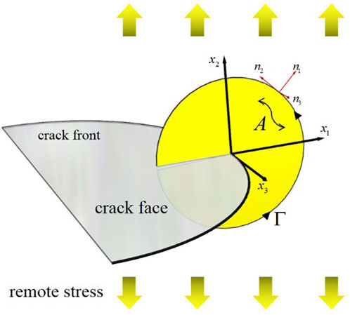
FIGURE 1. Calculation of the pointwise 3D J-integral of the crack front.
If the material is nonlinear elasticity,
If the material is nonlinear elastic and the condition is either plane-stress or plane-strain, 2) and 3) degenerate to the original two-dimensional form of the J-integral, as defined by Rice. The J-integral characterizes the behavior of crack propagation by the stress-strain state around the crack tip. In the case of a two-dimensional problem, the path-independence of the J-integral is easy to prove (Rice, 1968). The term
In the research of Newman and Raju (Raju and Newman, 1979), in order to characterize the relationship between surface crack stress intensity factor K and structure size, they fitted data and constructed a boundary correction factor containing six polynomials. Although it has great potential engineering value, there are too many parameters, and the scope of application of the expression is not broad enough. In this study, the calculated 3D J-integral results are not directly related to the characteristic parameters. In order to establish the relationship between the vessel geometry, material properties, crack morphology, internal pressure load, and the J-integral value, a correction factor is proposed in this study to characterize the influence of the elastoplastic material properties, crack tip singularity, and the geometric characteristics of the container on the J-integral. In the following study, we introduce the correction factor and study the relationship between factor F and characteristic parameters through ANNs.
According to the research of HRR (Hutchinson, 1968; Rice and Rosengren, 1968), the stress of the crack tip has stress singularity.
where
This study constructed the factor F as follows:
The term
Artificial neural networks (ANNs)
ANNs (Bishop, 1996) are calculation models formed by the interconnection of a great number of neurons. ANNs map the input to the output through being transformed repeatedly, to identify the highly complex and nonlinear relationship between data. Figure 2 shows the basic structure of NNs, which are composed of an input layer, a hidden layer, and an output layer. A single neuron consists of a set of weighted inputs, a bias term, a nonlinear activation function, and an output. Weights denote the importance of the corresponding input to the output, the bias term compensates the weighted average sum, and the activation function adds a nonlinear relationship to a single artificial neuron.
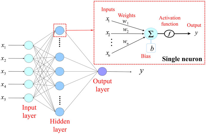
FIGURE 2. Single hidden layer neural network.
Among the commonly used NNs, the back-propagation neural network (BPNN) proposed by Rumelhart et al. (Rumelhart et al., 1988) has generally been adopted to deal with complex issues. BPNN is based on a back-propagation algorithm. This algorithm calculates the gradient of the loss function for all weights in the network, and this gradient is fed back to the optimization which can update the weights to minimize the loss. The calculation process is divided into two steps: feed-forward and back-propagation. In the feed-forward step, the network transfers the input data layer by layer. Then, the output layer collects signals from the last hidden layer to predict outputs. In the back-propagation step, if outputs are different from the target values, the loss is calculated through the loss function. The loss is returned along the original connection path, and the corresponding weights and biases are modified to minimize the loss. The detailed training process for BPNN is stated as follows:
First, all weights and biases are initialized to small values (He et al., 2015).
where summation is performed on all
A set of inputs are transmitted to the output layer, and finally a prediction output
where
Then the error of
where
The formulas of correction for the connection weights and biases are given by
where
The ANN-based safety assessment approach
In the present study, the effects of vessel geometries, material properties, crack size, and internal pressure on the 3D J-integral of elliptical cracks on the external surface of pressure vessels are investigated by FEM based on elastoplastic fracture mechanics. The calculated J-integral values and the vessel’s characteristic parameters are used to train NNs. Trained NNs can give similar results to the FEA for the unknown characteristic parameters of the pressure vessel to be tested. Meanwhile, they can evaluate the crack strength accurately and quickly. The process of implementation is shown in Figure 3.
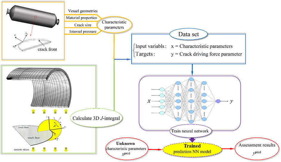
FIGURE 3. Flow diagram of safety assessment.
To build a reasonable training dataset of NNs, different internal pressure, geometric size of vessels, and crack size are considered. For each model, the static analysis is carried out and the J-integral values in the depth direction of crack propagation are calculated. The reasons for using the depth direction of J-integral are as follows: 1) mode
Finite element analyses
Material, modeling, and meshing
Ferritic low alloy steel A508-3 usually used for the pressure vessel in nuclear engineering. The material property at room temperature (22
where
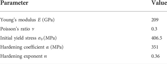
TABLE 1. Material parameters.
The simplified semi-elliptical crack morphology on the external surface of the pressure vessel is shown in Figure 4. The depth and length of the semi-elliptical crack are denoted as
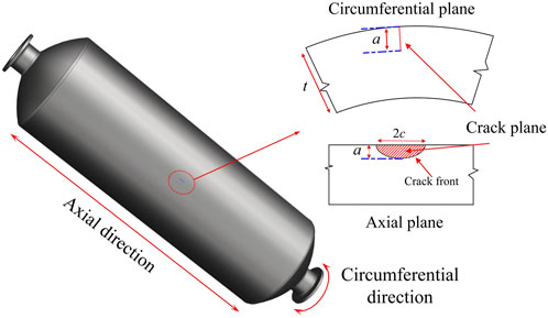
FIGURE 4. Semi-elliptical crack on the external surface of pressure vessels.
The commercial FE software COMSOL Multiphysics was used for the analyses. Since the model consists of a cylinder with a horizontal crack on its midplane, only a quarter of the whole geometry is built (as shown in Figure 5).
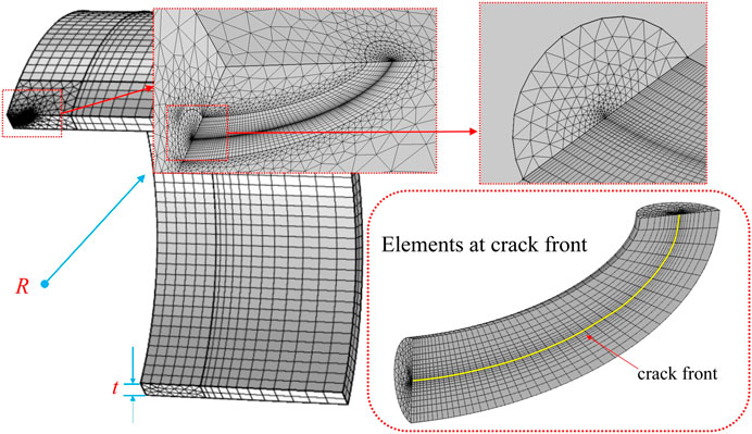
FIGURE 5. Finite element model and the mesh.
Numerical results
F is derived by Eq. 6 after the value of the J-integral is calculated. Parts of F-P curves are shown in Figure 6. In (A), (B), and (C), while keeping the vessel geometries (R, t) unchanged, the influence of the different crack aspect ratio a/c on F-P curves is shown with the increase of crack depth a. In (A), the case of shallow cracks, different a/c values have little effect on F. As the crack depth a increases in (B) and (C), the impact of a/c on F gradually increases, and the large a/c value limits the increasing trend of F. (D) and (E) show that the change of a/t has little effect on the relationship between the thickness radius ratio t/R and F when a/c and R are the same. Compared with (D) and (F), it can be seen that in the case of a shallow crack, the change of a/c has little effect on the relationship between t/R and F.
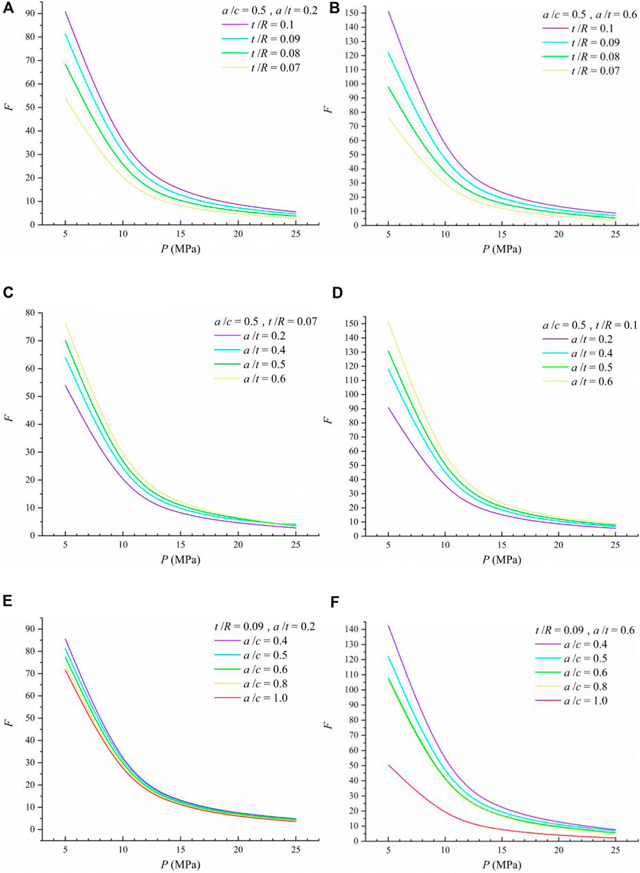
FIGURE 6. F-P curves from FEA. (A) F-P curve at different t/R (semi-elliptical, a/c = 0.5; shallow, a/t = 0.2); (B) F-P curve at different t/R (semi-elliptical, a/c = 0.5; deep, a/t = 0.2); (C) F-P curve at different a/t (semi-elliptical, a/c = 0.5; thin-walled, t/R = 0.07); (D) F-P curve at different a/t (semi-elliptical, a/c = 0.5; thick-walled, t/R = 0.1); (E) F-P curve at different a/c (relatively thick-walled, t/R = 0.09; shallow, a/t = 0.2); (F) F-P curve at different a/c (relatively thick-walled, t/R = 0.09 ; deep, a/t = 0.6).
A brief analysis of the data shows that 1) the influence of the geometric parameters (including vessel and crack) on F obviously decrease rapidly at first and then become flat. The change may be caused by the rapid propagation of the plastic zone area at the crack tip as shown in Figure 7 (surrounded by 0.2% equivalent plastic strain isoline), namely, the dominant factor of J-integral changes from geometry to plastic behavior. When the plastic zone is large, the F values of different geometries tend to be consistent. 2) With the complex interaction of the load, crack-front constraint, and material behavior result within, it is hard to find a generalized and explicit function to account for the relationship between F and characteristic parameters. Therefore, this study considers using the NN method to quantify the relationship.
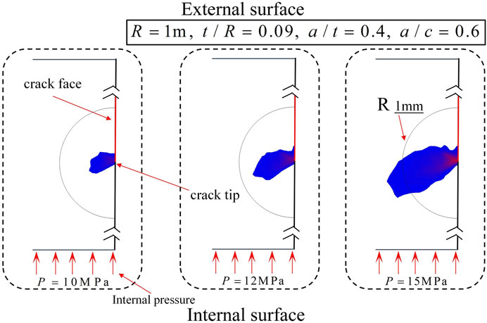
FIGURE 7. Plastic zone area at the crack tip under different internal pressure.
BPNN training and results
A better dataset plays a prominent part in training ANNs, including the combination of input variables and target values. The way that these data are defined can markedly affect the result. The importance of the dataset design has also been repeatedly emphasized by Liu et al. (Liu et al., 2021), and they also pointed out that a tailored machine learning method enables accurate knowledge extraction, even in a data-limited regime.
The correction factor
The value ranges of input variables are
The parameters’ values of the dataset including 1,200 cases comprises input x are listed in Table 2. In order to verify the generalization ability and accuracy of BPNN, 90% of the dataset is input into the ANN model for training, and 10% is reserved as the validation dataset. Finally, the accuracy of the solutions is measured by the mean absolute percentage error in the validation dataset.
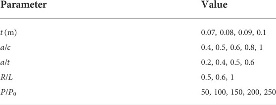
TABLE 2. Values of parameters in FEA.
Because the target variables in this problem are continuous and bounded over the whole input variables space, the accuracy of the BPNN over the continuous space can be reliably estimated reliably by sampling these discrete points (Liu et al., 2020).
The architecture of the BPNN mode to compute the 3D J-integral is illustrated in Figure 8. The open-source platform PyTorch v1.9.0 was used to establish and train networks. ReLU was used as the activation function, MSE loss function, and the Kaiming normal initialization method was adopted for the training process. The number of hidden layers and neurons affected the performance of NNs, which could only be tried repeatedly according to experience to achieve satisfactory results. The results show that the network with only three hidden layers and
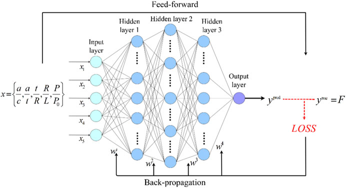
FIGURE 8. BPNN with 3 hidden layers.
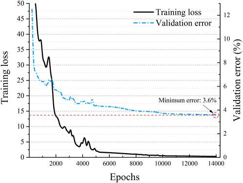
FIGURE 9. Result of the (5-64-256-64-1) BPNN.
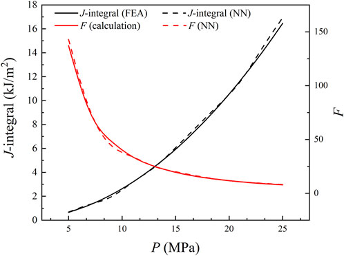
FIGURE 10. Accuracy of predicting unknown characteristic parameters.
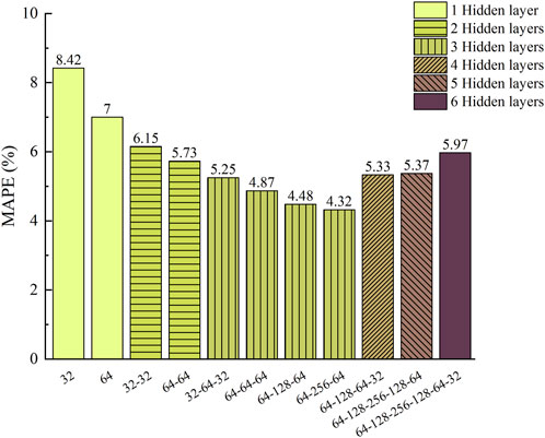
FIGURE 11. Accuracy of BPNNs.
Discussion and conclusion
In this work, the three-dimensional J-integral of an axial semi-elliptic crack on the external surface of an elastoplastic pressure vessel was studied for pressure vessels made of A508-3 steel, and various vessel sizes, crack sizes, and internal pressure loads were considered. Then the BP neural network was trained on a large number of calculated results to predict factor F, and the validation accuracy was more than 95% in the three hidden layer network. Finally, a fast pressure vessel safety evaluation framework based on the neural network was proposed. This method can save the manpower and time for repeated modeling and calculation, and achieve real-time prediction of the corresponding crack tip J-integral of the pressure vessel characteristic parameters.
The dimensionless correction factor F was used to represent the relationship between the pressure vessel characteristic parameters and 3D J-integral. Compared with using J-integral value directly as the result of measuring load action, the interval of F value was more stable, and its dimensionless property was conducive to the construction of the dataset.
The BP neural network with three hidden layers can accurately predict the 3D J-integral value. The constructed neural network can quickly predict the driving force of the crack tip on depth direction through the characteristic parameters of the pressure vessel to be measured, which is of certain significance to realize the real-time safety monitoring of the pressure vessel.
The traditional safety assessment method obtains the numerical relationship of the influencing factors by analyzing specific cases. The data collected is usually incomplete and inaccurate. The numerical relationship obtained is often not universal, which can often be modified again and again with the increase of cases. The main idea of this study is data-driven used in industrial automation, so we consciously generated a large number of regular and high-precision data. Based on the data, we studied the relationship between characteristic parameters and fracture parameters through machine learning methods, and realized the safety assessment of pressure vessels based on machine learning.
At present, existing research only focuses on one or two experimental materials, so it is impossible to construct a reasonable material parameter space for neural network learning, so such a single neural network does not have the ability to generalize material properties. How to use a neural network to establish a universally applicable relationship between material properties and fracture parameters is a major obstacle for the application of the neural network in pressure vessel safety assessment.
Data availability statement
The original contributions presented in the study are included in the article/Supplementary Material, and further inquiries can be directed to the corresponding author.
Author contributions
XZ: software, investigation, formal analysis, and writing—original draft; YH: conceptualization, analysis, resources, supervision, and writing—review and editing; JS: conceptualization; HL: conceptualization; YX: conceptualization; XC: conceptualization.
Funding
This research was funded by the National Natural Science Foundation of China (grant numbers 11972285 and 11872300), the Fund for the National Security Academic Fund (NSAF) (grant number U1630144), the Project Supported by Natural Science Basic Research Plan in Shaanxi Province of China (Program No. 2013JQ1008), and the Youth Innovation Team of Shaanxi Universities (Program No. 21JP079).
Conflict of interest
The authors declare that the research was conducted in the absence of any commercial or financial relationships that could be construed as a potential conflict of interest.
Publisher’s note
All claims expressed in this article are solely those of the authors and do not necessarily represent those of their affiliated organizations, or those of the publisher, the editors, and the reviewers. Any product that may be evaluated in this article, or claim that may be made by its manufacturer, is not guaranteed or endorsed by the publisher.
References
Akhi, A. H., and Dhar, A. S. (2021). Stress intensity factors for external corrosions and cracking of buried cast iron pipes. Eng. Fract. Mech. 250, 107778. doi:10.1016/j.engfracmech.2021.107778
Amestoy, M., Bui, H. D., and Labbens, R. (1981). On the definition of local path independent integrals in three-dimensional crack problems. Mech. Res. Commun. 8 (4), 231–236. doi:10.1016/0093-6413(81)90058-6
Atluri, S. N. (1982). Path-independent integrals in finite elasticity and inelasticity, with body forces, inertia, and arbitrary crack-face conditions. Eng. Fract. Mech. 16 (3), 341–364. doi:10.1016/0013-7944(82)90113-8
Blackburn, W. S. (1972). Path independent integrals to predict onset of crack instability in an elastic plastic material. Int. J. Fract. 8 (3), 343–346. doi:10.1007/BF00186134
Bloom, J. M. (1983). A procedure for the assessment of the structural integrity of nuclear pressure vessels. J. Press. Vessel Technol. 105 (1), 28–34. doi:10.1115/1.3264235
Bloom, J. M., and Malik, S. N. (1982). Procedure for the assessment of the integrity of nuclear pressure vessels and piping containing defects. CA, USA: Electric Power ResearchInstitute.
Bui, H. D. (1978). Stress and crack-displacement intensity factors in elastodynamics. Analysis Mech., 91–95. doi:10.1016/B978-0-08-022142-7.50026-0
Carpenter, W. C., and Read, D. T. (1984). Comments on the evaluation of the J integral. Int. J. Fract. 26 (2), R71–R74. doi:10.1007/BF01157558
Carpenter, W. C., Read, D. T., and Dodds, R. H. (1986). Comparison of several path independent integrals including plasticity effects. Int. J. Fract. 31 (4), 303–323. doi:10.1007/BF00044052
Castin, N., Malerba, L., and Chaouadi, R. (2011). Prediction of radiation induced hardening of reactor pressure vessel steels using artificial neural networks. J. Nucl. Mater. 408 (1), 30–39. doi:10.1016/j.jnucmat.2010.10.039
China Special Equipment Inspection & Research Institute (2021). Report of the State Administration for Market Regulation on the safety status of national special equipment in 2020.
China Standardization Committee on Boilers and Pressure Vessels (2019). Safety assessment of in-service pressure vessels containing defects (GB/T 19624-2019). Beijing, China: Administration for Market Regulation.
de Souza, R. F., and Ruggieri, C. (2015). J-dominance and size requirements in strength-mismatched fracture specimens with weld centerline cracks. J. Braz. Soc. Mech. Sci. Eng. 37 (4), 1083–1096. doi:10.1007/s40430-014-0249-5
Dodds, R. H. (1987). Finite element evaluation of J parameters in 3D. Int. J. Fract. 33 (1), R7–R15. doi:10.1007/BF00034901
Dodds, R. H., Carpenter, W. C., and Sorem, W. A. (1988). Numerical evaluation of a 3-D and comparison with experimental results for a 3-Point bend specimen. Eng. Fract. Mech. 29 (3), 275–285. doi:10.1016/0013-7944(88)90017-3
Dodds, R. H., and Read, D. T. (1990). Experimental and numerical studies of the J-integral for a surface flaw. Int. J. Fract. 43 (1), 47–67. doi:10.1007/BF00018126
Dodds, R. H., and Vargas, P. M. (1988). Numerical evaluation of domain and contour integrals for nonlinear fracture mechanics: Formulation and implementation aspects. Urbana-Champaign: University of Illinois Engineering Experiment Station. http://hdl.handle.net/2142/14167.
Duan, Chuanjie, and Zhang, Shuhua (2020). Prediction of fully plastic J-integral for weld centerline surface crack considering strength mismatch based on 3D finite element analyses and artificial neural network. Int. J. Nav. Archit. Ocean Eng. 12, 354–366. doi:10.1016/j.ijnaoe.2020.03.008
Ge, Qingyun, Zhai, Zhendong, Liu, Dongpo, and Guo, Dong (2005). Study of critical loads of thin-walled cylinder pressure vessel with crack. J. Archit. Civ. Eng. 17 (04), 54–56.
Hakimelahi, B., and Soltani, N. (2010). 3D J-integral evaluation using the computation of line and surface integrals. Fatigue & Fract. Eng. Mater. Struct. 33 (10), 661–672. doi:10.1111/j.1460-2695.2010.01478.x
He, Kaiming, Zhang, Xiangyu, Ren, Shaoqing, and Sun, Jian (2015). “Delving deep into rectifiers: Surpassing human-level performance on ImageNet classification,” in 2015 IEEE International Conference on Computer Vision, 1026–1034.
Holtam, C. M., Baxter, D. P., Ashcroft, I. A., and Thomson, R. C. (2011). A survey of fitness-for-Service Trends in Industry. J. Press. Vessel Technol. 133 (1), 014001. doi:10.1115/1.4001946
Hutchinson, J. W. (1968). Singular behaviour at the end of a tensile crack in a hardening material. J. Mech. Phys. Solids 16 (1), 13–31. doi:10.1016/0022-5096(68)90014-8
Kemp, R., Cottrell, G. A., Bhadeshia, H. K., Odette, G., Yamamoto, T., and Kishimoto, H. (2005). Neural-network analysis of irradiation hardening in low-activation steels. J. Nucl. Mater. 348 (3), 311–328. doi:10.1016/j.jnucmat.2005.09.022
Kishimoto, K., Aoki, S., and Sakata, M. (1980). On the path independent integral-. Eng. Fract. Mech. 13 (4), 841–850. doi:10.1016/0013-7944(80)90015-6
Knowles, J. K., and Sternberg, E. (1972). On a class of conservation laws in linearized and finite elastostatics. Arch. Ration. Mech. Anal. 44 (3), 187–211. doi:10.1007/BF00250778
Liu, Xing, Athanasiou, C. E., Padture, N. P., Sheldon, B. W., and Gao, H. (2020). A machine learning approach to fracture mechanics problems. Acta Mater. 190, 105–112. doi:10.1016/j.actamat.2020.03.016
Liu, Xing, Athanasiou, C. E., Padture, N. P., Sheldon, B. W., and Gao, H. (2021). Knowledge extraction and transfer in data-driven fracture mechanics. Proc. Natl. Acad. Sci. U. S. A. 118 (23), e2104765118. doi:10.1073/pnas.2104765118
Ma, Zhaoyang, Zheng, Yunhu, and Jiang, Feng (2015). Crack propagation prediction method for pressure vessels based on gray neural network optimization. Chem. Eng. Mach. 42 (03), 380–382+394.
Nabavi, S. M., and Shahani, A. R. (2008). Calculation of stress intensity factors for a longitudinal semi-elliptical crack in a finite-length thick-walled cylinder. Fatigue Fract. Eng. Mat. Struct. 31, 85–94. doi:10.1111/j.1460-2695.2007.01203.x
R6 (2013). Assessment of the integrity of structures containing defects, Revision 4, including subsequent updates. UK: Gloucester.
Raju, I. S., and Newman, J. C. (1979). Stress-intensity factors for a wide range of semi-elliptical surface cracks in finite-thickness plates. Eng. Fract. Mech. 11 (4), 817–829. doi:10.1016/0013-7944(79)90139-5
Raju, I. S., and Newman, J. C. (1982). Stress-intensity factors for internal and external surface cracks in cylindrical vessels. J. Press. Vessel Technol. 104 (4), 293–298. doi:10.1115/1.3264220
Rice, J. R. (1968). A path independent integral and the approximate analysis of strain concentration by notches and cracks. J. Appl. Mech. 35 (2), 379–386. doi:10.1115/1.3601206
Rice, J. R., and Rosengren, G. F. (1968). Plane strain deformation near a crack tip in a power-law hardening material. J. Mech. Phys. Solids 16 (1), 1–12. doi:10.1016/0022-5096(68)90013-6
Rumelhart, D. E., Hinton, G. E., and Williams, R. J. (1988). Learning internal representations by error propagation. Readings Cognitive Sci., 399–421. doi:10.1016/b978-1-4832-1446-7.50035-2
Sakata, M., Aoki, S., Kishimoto, K., and Takagi, R. (1983). Distribution of crack extension force, the J-integral, along a through-crack-front of a plate. Int. J. Fract. 23 (3), 187–200. doi:10.1007/bf00028822
Strifors, H. C. (1974). A generalized force measure of conditions at crack tips. Int. J. Solids Struct. 10 (12), 1389–1404. doi:10.1016/0020-7683(74)90089-4
Sumpter, J. D., and Turner, C. E. (1976). Use of the J contour integral in elastic-plastic fracture studies by finite-element methods. J. Mech. Eng. Sci. 18 (3), 97–112. doi:10.1243/JMES_JOUR_1976_018_019_02
Thresher, R. W., and Smith, F. W. (1972). Stress-intensity factors for a surface crack in a finite solid. J. Appl. Mech. 39 (1), 195–200. doi:10.1115/1.3422611
Yang, Wanhuan, Zhong, Weihua, Li, Junwan, Li, Shuai, Ning, Guangsheng, and Yang, Wen (2021). Necking behavior of small tensile specimen of domestic A508-3 steel. Atomic Energy Sci. Technol. 55 (07), 1177–1183.
Young, Do, Ye, Ji’an, Kim, C. H., and Na, M. G. (2019). Nuclear reactor vessel water level prediction during severe accidents using deep neural networks. Nucl. Eng. Technol. 51 (3), 723–730. doi:10.1016/j.net.2018.12.019
Keywords: three-dimensional J-integral, fracture, artificial neural network, pressure vessel, surface crack
Citation: Zhang X, Hu Y, Shi J, Liang H, Xu Y and Cao X (2022) A safety assessment approach to pressure vessels based on machine learning. Front. Mater. 9:1051890. doi: 10.3389/fmats.2022.1051890
Received: 23 September 2022; Accepted: 10 October 2022;
Published: 02 November 2022.
Edited by:
Qun Li, Xi’an Jiaotong University, ChinaReviewed by:
Jianshan Wang, Tianjin University, ChinaXiaoming Liu, Institute of Mechanics (CAS), China
Liguo Zhao, Loughborough University, United Kingdom
Copyright © 2022 Zhang, Hu, Shi, Liang, Xu and Cao. This is an open-access article distributed under the terms of the Creative Commons Attribution License (CC BY). The use, distribution or reproduction in other forums is permitted, provided the original author(s) and the copyright owner(s) are credited and that the original publication in this journal is cited, in accordance with accepted academic practice. No use, distribution or reproduction is permitted which does not comply with these terms.
*Correspondence: Yifeng Hu, eWZodUB4YXV0LmVkdS5jbg==