 Yuting Li1†
 Shude Ji
94% of researchers rate our articles as excellent or good
Learn more about the work of our research integrity team to safeguard the quality of each article we publish.
Find out more
ORIGINAL RESEARCH article
Front. Mater. , 20 October 2022
Sec. Structural Materials
Volume 9 - 2022 | https://doi.org/10.3389/fmats.2022.1039580
This article is part of the Research Topic Joining and Welding of New and Dissimilar Materials - Volume II View all 6 articles
The non-keyhole friction stir lap welding (N-KFSLW) technology assisted by the outer stationary shoulder and the inner upper half-thread rotating pin was proposed to obtain the welding joint without keyhole through one-time process. Choosing 2024 aluminum alloys as the research object, the formation, microhardness and tensile strength of N-KFSLW joint were investigated. The improved particle swarm optimization (IPSO) algorithm was newly developed and had the advantages of large convergence speed and strong search ability, by which the radial basis function (RBF) neural network was optimized to enhance its prediction accuracy. After that, the RBF and IPSO (IPSO-RBF) system was used to predict the joint strength and optimize the process parameters combination. The results showed that the lap joint had not only the SZ with the thickness almost equal to the thickness of upper sheet but also the cold lap with a very small height, thereby leading to the high tensile strength of joint. The optimized parameters of welding speed, rotating speed and pin type by the IPSO-RBF system were respectively 612 rpm, 80 mm/min, and upper half-thread pin, and the tensile strength of lap joint reached 11.88 kN/mm. The N-KFSLW technology assisted by upper half-thread pin provides an effective way to obtain the lap joint with high performance, and the IPSO-RBF system can be used to maximize the strength of welding joint.
As a representative of lightweight alloy, aluminum (Al) alloys are essential in the automotive, aerospace, and shipbuilding industries for their high specific strength and favorable formability (Naumov et al., 2019; Xie et al., 2022). Friction stir welding (FSW) is a solid-state welding technique which has been widely investigated to join light alloys due to its high weld quality, no pollution, and low energy consumption (Ren et al., 2020b). However, for the traditional FSW process, the rotating pin is withdrawn from the plate at the end of welding, thereby forming a keyhole. The existence of keyhole not only reduces the mechanical properties of joint but also affects the overall aesthetics of weld (Meng et al., 2021b). In recent years, eliminating the keyhole has been becoming a hotspot of research. The reported method to eliminate the keyhole is mainly focused on repairing the keyhole after welding, such as self-refilling friction stir welding (SRFSW) (Zhou et al., 2013), friction plug welding (FPW) (Du et al., 2019), filling friction stir welding (FFSW) (Huang et al., 2013) and active-passive filling friction stir repairing (A-PFFSR) (Meng et al.; Zhao et al., 2021) and so on. The repairing methods after welding increase the process complexity. Gong et al. (Gong et al., 2021; Gong et al., 2022) proposed a new FSW technique named as non-keyhole friction stir welding (N-KFSW) to eliminate the keyhole during the welding process. This technique effectively combines the refill friction stir spot welding (RFSSW) and the FSW because its rotational tool is the same as that for RFSSW, and can obtain the non-keyhole welding joint through one-time process. So far, the N-KFSW process has only been used to weld the butt joint rather than the lap joint.
In the process of FSW, welding process parameters (welding speed, rotating speed, and so on) are the key factors in determining the strength of welding joint, and the relationships between them are nonlinear and complicated (Chien et al., 2011). The control variate method is always used to obtain reasonable process parameters by plenty of experiments (Liu et al., 2015), but the corresponding result is difficult to achieve the optimal parameter combination precisely. To obtain the joint with higher strength, more and more experimental design methods have been introduced into the parameter optimization of FSW process, such as response surface methodology (Kim et al., 2010) and Taguchi method (Chanakyan and Sivasankar, 2020). Compared with these experimental design methods, the combination of artificial neural network (ANN) and population-based intelligence algorithm has greater advantages in parameter prediction and hybrid multi-objective optimization, which can find out the better process parameters combination to improve the strength of welding joint (Soori et al., 2021; Asmael et al., 2022). Song et al. (2020) used radial basis function (RBF)-grey wolf optimizer (GWO) system to optimize the welding process parameters of Al/Mg dissimilar alloys FSW. Their results showed that the predicted error of model established by RBF neural network was 3.2%, and the tensile strength of the optimized joint reached 158 MPa, which was 3.9% higher than the reported maximum strength value. Medhi et al. (2021) established the NSGA-Ⅱ-ANN system to optimize welding process parameters of dissimilar Al/Cu hybrid FSW. They stated that the prediction error of 2.8% was acquired by the ANN model, and the joint tensile strength of 142.32 MPa by optimal process parameters was 17% higher than the maximum strength before optimization.
As a shallow neural network, RBF neural network is very popular because of its fast training speed and good nonlinear fitting performance. Although RBF neural network has been widely used, improperly selecting its some key parameters such as the center and width of hidden layer basis functions and connected weight between hidden layer and output layer always leads to large network convergence error and bad generalization capacity (Sun et al., 2016). In order to further determine the mapping relationship between input and output and then improve the generalization ability of RBF neural network, optimizing the key parameters of RBF neural network by population-based intelligence algorithm with superior search ability is proved to be an effective way. Yu et al. (2020) introduced the particle swarm optimization (PSO) algorithm to optimize the center vector and width of RBF in the hidden layer and the link weight of line output in the output layer. Their results showed that the average recognition rate using PSO-RBF neural network was 97.115%, which was 4% higher than that using RBF neural network. As one of the population-based intelligence algorithms, PSO algorithm is widely used in parameter optimization, neural network optimization and other fields due to its advantages of simple implementation and few adjustment parameters (Dong et al., 2020; Yin et al., 2020). However, the single PSO algorithm has the problem of easily falling into local extremum. This problem can be solved by several reported methods such as optimizing its initial population (Ren et al., 2020a) and introducing multi swarm improvement method to increase search ability (Srinivasulu, 2021).
In this study, the N-KFSW technology was used to weld the lap joint, and this technology was called as non-keyhole friction stir lap welding (N-KFSLW). The improved PSO (IPSO) algorithm was firstly developed by increasing a new search method which was inspired by PIO algorithm to overcome the problem of easily falling into local extremum of single PSO algorithm. Then, the IPSO-RBF system was established to predict the joint strength and optimize the process parameters combination. Finally, the lap interface morphologies, microstructures, microhardnesses and fracture behaviors under different process parameter combinations were compared to explain why the optimal process parameters combination could obtain the highest tensile strength of N-KFSLW joint.
Two and four millimeter thick 2024 Al alloy plates were used as the base materials (BMs), and other dimensions of plate were 300 and 150 mm. The chemical composition and mechanical properties of BM are shown in Table 1. Two plates were lap combined with a lap width of 50 mm, while 2 mm thick plate was selected as upper sheet of joint to be welded. Figure 1 shows the lap configuration of plates and the specific dimensions of the N-KFSLW tool. Similar to the N-KFSW process (Gong et al., 2021; Gong et al., 2022), the N-KFSLW process also has four stages including plunging stage, welding stage, refilling stage and leaving stage, and this study mainly studied the joint performance at the welding stage. Therefore, a simplified welding tool consisting of the stationary shoulder and an internal rotating hollow pin was designed, as shown in Figure 1B. The inside and outside diameters of stationary shoulder were 6 and 16 mm, respectively. The diameters of pin and hollow part were respectively 6 and 3 mm, and the pin length was 2.5 mm (Figure 1B). Before welding, the plate surfaces contacting the tool during welding were cleaned with 500# sand papers to wipe off oxide films. During welding, the plunge depth of stationary shoulder was 0.15 mm. For the FSLW process, the tool shoulder need slightly plunges into the upper surface of plate to provide a forging function on the welded joint. The rational tilting angle of tool can not only ensure the forging function to avoid the appearance of defects in the stir zone (SZ), but also reduce the forward resistance of tool by the materials before the tool. Wan and Huang (2017) reported that the tilting angle of 2.5° rather than 0° or 1.5° eliminated welding defects including micro voids, cracks and even tunnel defects in FSLW. In this paper, the 2.5° tilting angle of welding tool was chosen, and this tool rotated counterclockwise and moved along the weld centerline. After welding, an electrical discharge cutting machine was used to cut the tensile specimens and the metallographic samples. Tensile test specimens were prepared as per the ISO 9018:2003, and the static tensile strength test were carried out at a loading rate of 2 mm/min on tensile testing machine (SHIMADZUEHF-UV200K2) at room temperature. Three tensile specimens for N-KFSLW process were used to determine the average tensile strength of the joint under each set of process parameters. Metallographic samples were prepared as per the ISO 17639:2003(E), and they were cut next to the tensile specimen. Then, an optical microscope (OM, Olympus-GX71) was used to observe the joint microstructure. A scanning electron microscope (SEM, SU3500) was used to analyze the joint fracture characteristics. The microhardness of joint was measured by a microhardness tester (Wilsen VH1102) and the corresponding specimens were prepared according to the ISO 9015-2:2003.
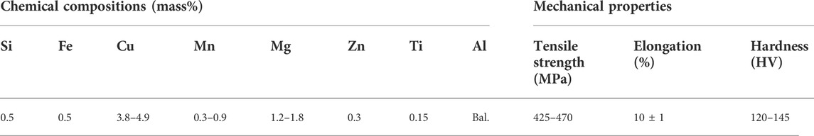
TABLE 1. Chemical composition and mechanical properties of the 2024 Al alloy.

FIGURE 1. Schematic diagrams: (A) N-KFSLW process, (B) dimensions of stationary shoulder and rotational pin.
The RBF neural network is used to map the non-linear relationship between a series of inputs and the investigated outputs, and is extensively applied in the domain of data prediction due to its strong self-learning ability and generalization ability (Nasir et al., 2020). The RBF structure is comprised of input layer, hidden layer and output layer. The input layer plays the role of transmitting signals, the radial basis function including the center and width parameters of radial basis in the hidden layer maps the input vector to the hidden layer space, and the output vector is weighted and then linearly mapped from the hidden layer space. Therefore, the adjustable parameters in the RBF neural network include the center vector and width of radial basis function in the hidden layer and the link weight of line output in the output layer (Gong et al., 2012). The numbers of neurons at input layer, hidden layer and output layer are equal to the inputs, the size of input data and the outputs, respectively. The RBF neural network model established in this study is shown in Figure 2. The centers, widths and weights of RBF neural network decide the network convergence speed and accuracy. They are randomly generated in traditional RBF neural network, which always negatively influences the model accuracy. Therefore, the intelligent algorithm of IPSO is used to optimize the RBF neural network in this study.
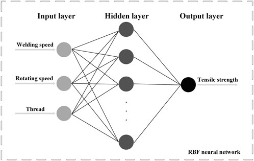
FIGURE 2. RBF neural network model for N-KFSLW process.
The swarm intelligence optimization algorithm is designed by the mechanisms of group biosocial behavior. As the swarm intelligence optimization algorithm, PSO has the advantages of simplicity, few parameters and fast convergence (Sun et al., 2016). The particles in PSO algorithm update their velocities and positions by the follow formula (Sun et al., 2016) at
Where
However, the PSO algorithm has the disadvantages of easily falling into the local optimum and long training time. To make particles in iterations move closer to a search area to get the optimal solution at a faster speed, it is necessary to improve the PSO algorithm (Liang et al., 2006).
As another swarm intelligent optimization algorithm, the PIO algorithm was innovatively proposed by Sun et al. (2014) based on simulating pigeons’ homing behavior. There are two iterative operators in the process of PIO algorithm, which are the map and compass operator and the landmark operator. The general direction of iteration is firstly judged by the map and compass operator, and then the current direction is revised by the landmark operator. Therefore, the PIO algorithm has the advantages of clear search direction and strong robustness. In the process of landmark operator, the position
Where
Based on these above-mentioned equations, the IPSO algorithm is obtained by utilizing the PIO algorithm to optimize the PSO algorithm. After the PSO algorithm updates the position and velocity of particle, the new position updating equations which are inspired by the idea of landmark operator in PIO algorithm are used to update the particle position again. The new position updating equations are as follows.
Where
In order to verify the effectiveness and advantages of the IPSO algorithm, four unimodal benchmark functions and four multimodal benchmark functions were selected from 23 classical benchmark functions utilized by many researchers to test the IPSO algorithm (Liang et al., 2006; Mirjalili et al., 2014). These benchmark functions are listed in Tables 2, 3 where
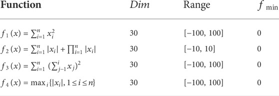
TABLE 2. Unimodal benchmark functions.
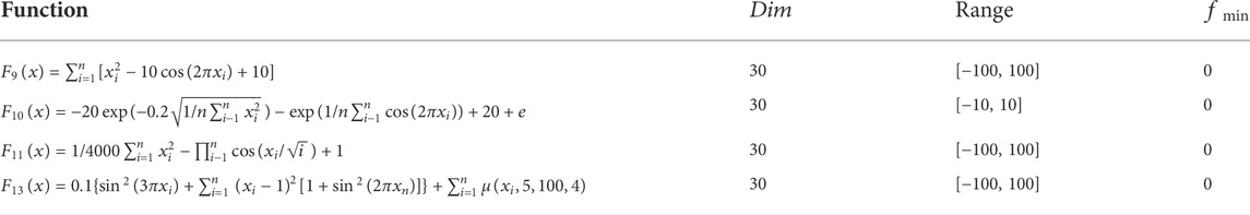
TABLE 3. Multimodal benchmark functions.
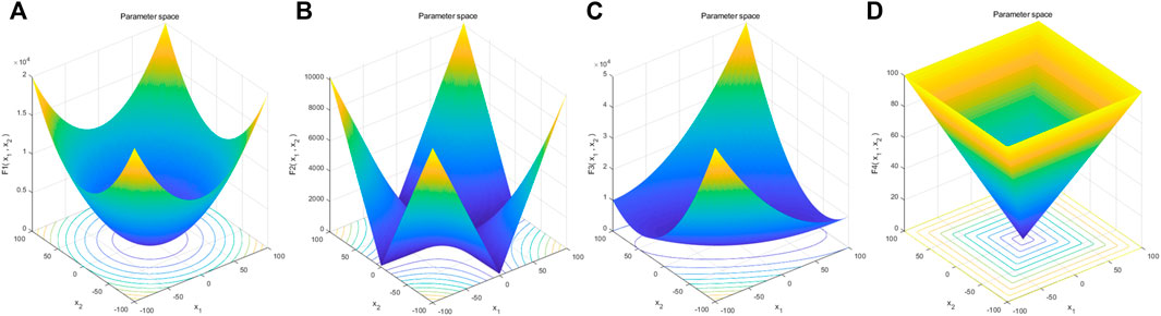
FIGURE 3. 2-D versions of unimodal benchmark functions in Table 1: (A)
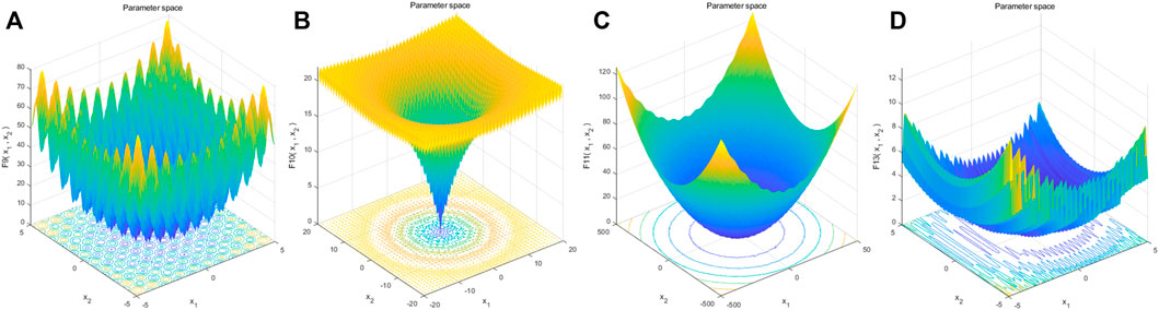
FIGURE 4. 2-D versions of multimodal benchmark functions in Table 2: (A)
The PSO algorithm and IPSO algorithm were run 30 times on each benchmark function, and the statistical results (average and standard deviations) are listed in Table 4. It is found that IPSO algorithm shows strong competitiveness in the search for optimum of the unimodal benchmark functions, and the average and standard deviations by IPSO algorithm are better than those by PSO algorithm. The unimodal benchmark function is suitable for benchmark test development (Mirjalili et al., 2014), and the results in Table 4 demonstrate the superior performance of IPSO algorithm in developing optimal parameters. Compared with unimodal benchmark functions, multimodal benchmark functions have many local optimums and can be used to benchmark the abilities of algorithm including searching and avoiding local optimum (Mirjalili et al., 2014). On the basis of the results in Table 4, it is known that the IPSO algorithm also has the advantages of finding optimum on multimodal benchmark functions, which proves that the proposed algorithm is not easy to fall into local optimum and has good searching performance. These two superior abilities of IPSO algorithm is because the locations of individuals of the population are increased under the new position updating equations. Therefore, the improvement strategy of PSO algorithm proposed in this study is reliable.

TABLE 4. Results of benchmark functions.
In this study, the IPSO-RBF system means the combination of IPSO-RBF neural network and IPSO algorithm. The IPSO-RBF neural network means the RBF neural network whose parameters are optimized by the IPSO algorithm, which is used to establish the prediction model of joint tensile strength for the N-KFSLW technology. On basis of this prediction model, the IPSO algorithm is further used to obtain the optimal welding process parameters of N-KFSLW technology. Figure 5 shows the flow chart of the optimization process by IPSO-RBF system.
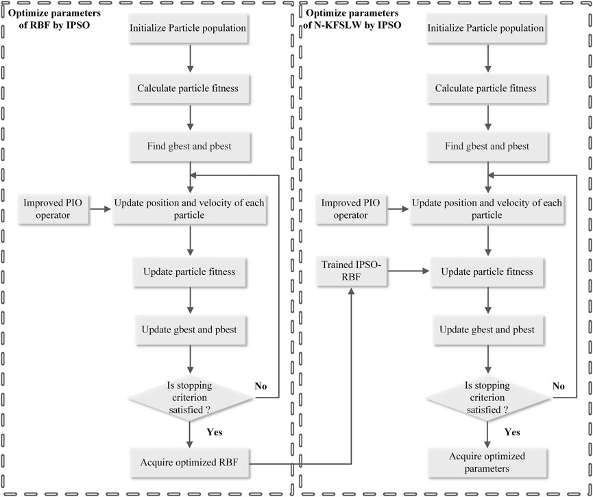
FIGURE 5. Flow chart of optimization process of IPSO-RBF system.
The IPSO-RBF neural network established in this study needs experiment data to train and then achieve the desired prediction accuracy. For the butt joint by FSW, the tensile properties include the tensile strength and elongation (Chien et al., 2011; Venkateswarlu et al., 2013). However, researchers always choose the tensile shear load as the tensile property to evaluate the quality of FSLW (Li et al., 2016; Liu et al., 2018; Wang et al., 2020). Thus, the welding speed, rotating speed and the pin type in experiment data are used as the input of neural network, and the output is the tensile strength of joint in this paper. Table 5 lists the experiment results in this study. Figure 6 showed the load-displacement curves of lap joints under typical parameter combinations. During FSLW, tool geometries have a strong influence on material flow in SZ (Ji et al., 2017). To explore the effect of pin thread on the quality of welding joint, three types of pin were used in welding experiment. They are respectively the pin with full right hand thread, the pin with a half thread starting from pin tip to its middle position, and the pin with a half thread starting from the pin middle position to its bottom, which are respectively named as the full-thread pin, the upper half-thread pin and the below half-thread pin in this study. In the IPSO-RBF neural network, the upper half-thread pin, the full-thread pin and the below half-thread pin are respectively represented by the numbers of 0, 1 and 2.
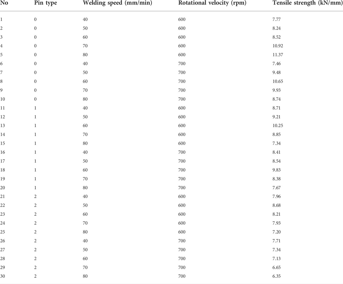
TABLE 5. Training and testing data samples for IPSO-RBF.
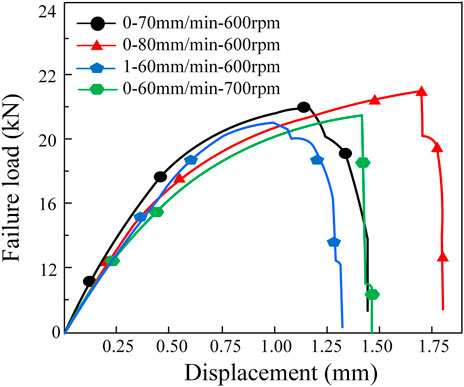
FIGURE 6. Load-displacement curves.
The establishment of prediction model by IPSO-RBF neural network and the optimization of welding process parameters by IPSO algorithm were performed by the MATLAB software. In training stage of IPSO-RBF neural network, 27 data sets and 3 data sets in Table 5 were used to train and then test the IPSO-RBF neural network, respectively.
The relative error between predicted value and experimental value is used to evaluate the prediction accuracy of IPSO-RBF neural network, and its equation is as follows (Medhi et al., 2021).
Where
Figure 7A displays the evolutionary curves of the error under RBF neural network, PSO-RBF neural network and IPSO-RBF neural network. The results present that IPSO-RBF neural network has the minimum prediction error of 1.7%, and the larger prediction errors of 3.2% and 7.3% are obtained respectively under PSO-RBF neural network and under RBF neural network. The prediction model of joint tensile strength converges after 50 times of training under IPSO-RBF neural network, and the corresponding times are 100 under PSO-RBF neural network and 130 under RBF neural network. Compared with RBF neural network and PSO-RBF neural network, the IPSO-RBF neural network has the largest predicted accuracy and the fastest convergence speed. Therefore, the prediction model of welding parameters was established quickly and accurately by IPSO-RBF system. Figures 7B,C show the predicted tensile strengths and the relative errors of three different neural networks. The prediction error of IPSO-RBF neural network has the smallest fluctuation. It is known that compared with RBF neural network and PSO-RBF neural network, the IPSO-RBF neural network has the lowest error.
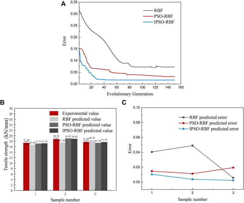
FIGURE 7. Training and predicted results under different neural networks: (A) evolutionary curves, (B) predicted tensile strengths and (C) relative errors between predicted and verified results.
Based on IPSO-RBF neural network, the next stage is optimizing the welding process parameters of N-KFSLW by IPSO algorithm. After 500 iterations of IPSO algorithm optimization, the best parameters of thread, welding speed and rotational velocity are achieved, which are the upper half-thread pin, 80 mm/min and 611.97 rpm, respectively.
According to the optimum process parameter combination, the executable solution of N-KFSLW technique is selected to perform the confirmation experiment. Table 6 shows the executable optimum process parameters and the corresponding tensile strength. The tensile strength acquired by the IPSO-RBF system is 11.74 kN/mm. The experimental tensile strength of 11.88 kN/mm is close to the predicted result and the corresponding deviation is 1.2%, which is within the acceptable range and verifies the accuracy of the IPSO-RBF system. Moreover, compared with the highest tensile strength of 11.37 kN/mm in Table 5, the tensile strength under optimum process parameters is increased by 4.5%, which reveals the effectiveness of the IPSO-RBF system established in this study.

TABLE 6. Executable optimum process parameters and their corresponding joint strength.
In this study, the high-strength lap joint presented the tensile fracture mode, and the void and cracks defects were discussed in order to more clearly explain the fracture mechanism of N-KFSLW joint, as displayed in Figure 8. When the low ratio of rotational velocity and welding speed is used, the void defect may appear in the advancing side (AS) of SZ (Figure 8A) due to the insufficient material flow. For the lap joint, the cold lap is made up of two alclad layers including the bottom surface of upper sheet and the top surface of lower sheet, and these two layers are bonded only by atom diffusion (Glaissa et al., 2020). The cold lap on the retreating side (RS) extends into SZ presenting the morphology of first upwards-bending and then downwards-bending (Liu et al., 2018). Therefore, the crack always appears in the cold lap around the SZ outline due to the existence of the original lap interface and the relatively low temperature during welding, and its tip may be in the SZ (Li et al., 2016) or outside the SZ (Xiao et al., 2021). In this study, the crack tip in the high-strength lap joint is located outside the SZ (Figure 8B). The lap joint can be divided into configurations A and B, and configuration B means the RS of lap joint bears the main load during the tensile test (Ji et al., 2017). When the lap joint with configuration B undergoes the external tensile load, the crack propagates along the cold lap at the RS to the highest point of cold lap and then upwards, thus leading to the tensile fracture mode (Figure 8C). In this case, the crack path is located at the RS of SZ which owns microhardness higher than the thermo-mechanically affected zone (TMAZ), so the corresponding tensile shear load of joint is mainly related to the crack in Figure 8B rather than the void at the AS of SZ (Figure 8A). Figure 8D displays the macro morphology of joint fracture surface, and the enlarged views of local regions marked in Figure 8D are displayed in Figures 8E–G. The microstructure of the whole fracture was observed by the SEM, and it shows inconsistent illumination and roughness (Figure 8D). In region E, there exist some small-size dimples with low depth (Figure 8E). From the above-mentioned analysis, it is concluded that region E located in the alclad layer has the very low bonding strength. This is why the dimples in region E are few and shallow (Figure 8E). Regions F and G are located above the cold lap and have relatively high bonding strength between materials, so these regions are characterized by many dimples with various sizes, as displayed in Figures 8F,G. Certainly, the dimples in Figures 8F,G are elongated and directional under the action of shear force. The fracture surface morphology presents that the fracture mode of N-KFSLW joint belongs to the ductile fracture mode.
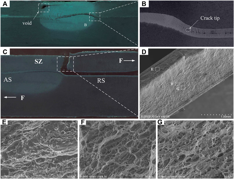
FIGURE 8. (A) Cross section of the joint at low rotating speed ratio and (B) enlarged views of region B; (C) Cross section and (D) fracture surface morphology of joint with tensile fracture mode; enlarged views of local regions marked in (D): (E) region E, (F) region F and (G) region G.
When the lap joint presents the tensile fracture mode, the key factor on influencing the joint strength is the height of cold lap of joint and the mechanical properties of material on the fracture path. Moreover, similar to the joint of No. 5 which owns the highest tensile strength before optimization in Table 5, the joint under the optimum process parameters is fabricated by the upper half-thread pin. Thus, the lap interface feature, microstructure and mechanical property of joint by upper half-thread pin are analyzed in detail in the following part. In order to explain why the joint under optimum process parameters combination by the IPSO-RBF system has the highest tensile strength, the joint of No. 5 in Table 5 was selected for comparison because it has higher tensile strength than other joints in Table 5. These two joints by the upper half-thread pin are respectively named as the optimized joint and the No. 5 joint.
The joint top surface is shown in Figure 9A. Due to the action of stationary shoulder (Wu et al., 2015), the joint with a smooth surface is attained, which has no flashes and shoulder marks. The joint cross sections under different welding parameter combinations are displayed in Figures 9B,C. Similar to traditional FSLW joint (Wang et al., 2020), the N-KFSLW joint consists of SZ, heat affected zone (HAZ) and TMAZ and BM. There is no cavity inside the SZ, and the thickness of SZ is almost equal to that of the BM due to the seal barrier effect of stationary shoulder of N-KFSLW tool in Figure 1. The TMAZ and HAZ are outside the SZ, which is not directly stirred by the welding tool. Because the welding tool used in this study has no rotating shoulder and the stationary shoulder has the heat-absorbing action (Patel et al., 2022), the HAZ and TMAZ both present the narrow-band shape. For FSLW process, the hook defect outside the SZ and cold lap extending into the SZ are formed inside the joint under the action of welding tool. These two structures are the key factors affecting the bearing capacity of joint. A reasonable rotational tool and appropriate welding parameters can control the morphologies of hook defect and cold lap and then improve joint quality immensely (Liu et al., 2016; Meng et al., 2021a). During the FSLW process, material concentrated area (MCA) is always produced at the end of thread on the pin (Ji et al., 2017). For the traditional full-thread pin, the MCA is located around the pin tip, and pushes the materials in TMAZ to transfer upwards, thereby making that the hook defect and cold lap always own large height. In this study, the upper half-thread pin length is 2.5 mm and the thickness of upper sheet is 2 mm. Therefore, when the upper half-thread pin is used, the MCA is located above the original lap interface and exerts a downward force on the lap interface (Figure 9D), thereby leading to the relatively small heights of hook defect and cold lap structures. In this study, the height of cold lap of optimized and No. 5 joints by the upper half-thread pin are 0.491 and 0.584 mm, respectively. Compared with the No. 5 joint, the height of cold lap of optimized joint is decreased by 15.9%. Therefore, the more proper welding parameters are obtained by the IPSO-RBF system from the viewpoint of reducing the cold lap of welding joint, which is beneficial to enhancing the joint bearing capacity.
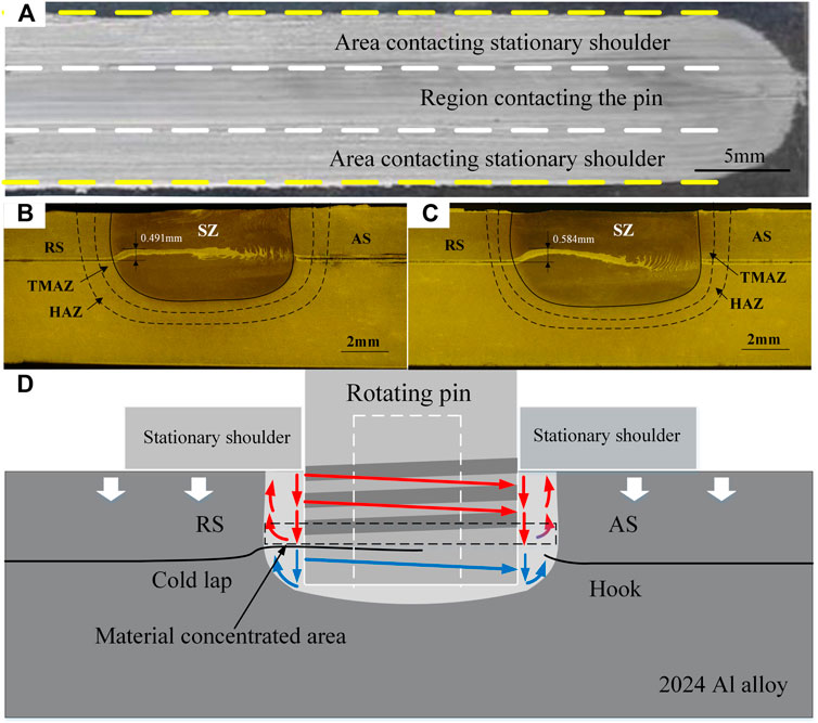
FIGURE 9. Joint formations: (A) joint surface; cross sections of joints: (B) optimized joint and (C) No. 5 joint; (D) schematic diagram of material flow during N-KFSLW.
Figure 10 displays the microstructures of typical zones of N-KFSLW joint. The BM is composed of lath-shape grains with large size (Figure 10A). During the welding process, HAZ only experiences the thermal cycle action rather than the mechanical stirring experienced by the SZ (Li et al., 2016), so its grain is enlarged and the corresponding size (Figure 10B) is larger than that in BM (Figure 10A). Different from the HAZ, the SZ undergoes not only the welding temperature higher than the recrystallization temperature but also the sufficient material flow, thereby leading to the complete dynamic recrystallization. Therefore, the SZ of N-KFSLW joint is characterized by fine and equiaxed grains and its grain size is much smaller than that in BM. In this study, the linear intercept measurement method was used to obtain the grain size of SZ, and the optimized and No. 5 joints were both analyzed for explaining why the optimized joint owns the highest tensile strength because the fracture path is located at the SZ (Figure 8A). For the optimized joint (Figure 10C), the grain size of SZ is 9.58 μm. For the No. 5 joint (Figure 10D), the grain size of SZ is 8.66 μm. Compared with the No. 5 joint, the optimized joint has the SZ with slightly larger grain size. By comparing the welding parameters for the No. 5 joint with that for the optimized joint, it is known that the rotational velocity of 612 rpm for the optimized joint is larger than 600 rpm for the No. 5 joint. Higher rotational velocity causes higher welding temperature (Selvaraj et al., 2013) and more serious material flow (Kumar et al., 2018). Generally speaking, more serious material flow is beneficial to refining the grain size, but higher welding temperature can enlarge the grain size. Therefore, from the viewpoint of influencing the grain size, enlarging the grain size by increasing welding temperature for the SZ of optimized joint plays the dominant role, thereby making that the optimized joint rather than the No. 5 joint has the SZ with larger grain size.
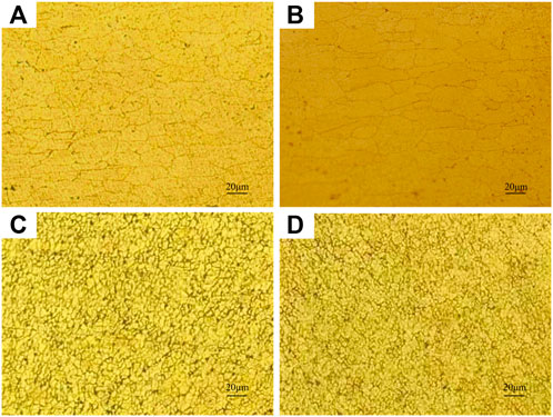
FIGURE 10. Microstructures of typical zones: (A) BM, (B) HAZ of optimized joint, (C) SZ of optimized joint and (D) SZ of No. 5 joint.
The microhardness distributions of the No. 5 and optimized joints were measured and the results are displayed in Figure 11. In this study, the two lines were performed to measure the microhardness. One is parallel to the original lap interface of joint and is 1 mm away from the top surface of joint, the other is perpendicular to the original lap interface and is located near the fracture path of joint (Figure 11A). When the welding process parameters combination is changed, the microhardness distribution is nearly the same. The microhardness values of SZ, HAZ and TMAZ are all smaller that the value of BM, because the 2024 Al alloy is a kind of age-hardenable Al alloy and the welding thermal cycle during welding can lead to the softening of materials (Chen et al., 2017). According to the Hall-Petch relationship (Tian et al., 2019), decreasing grain size is beneficial to obtaining higher microhardness. In this study, the SZ is composed of greatly refined grains due to the dynamic recrystallization while the grains in HAZ are enlarged, so the SZ owns the higher microhardness compared with the HAZ. Therefore, the microhardness distribution parallel to the original lap interface presents a W shape and the lowest microhardenss value is located near the boundary between the TMAZ and the HAZ (Figure 11B), which is similar to the results reported by Jiang et al. (2016).
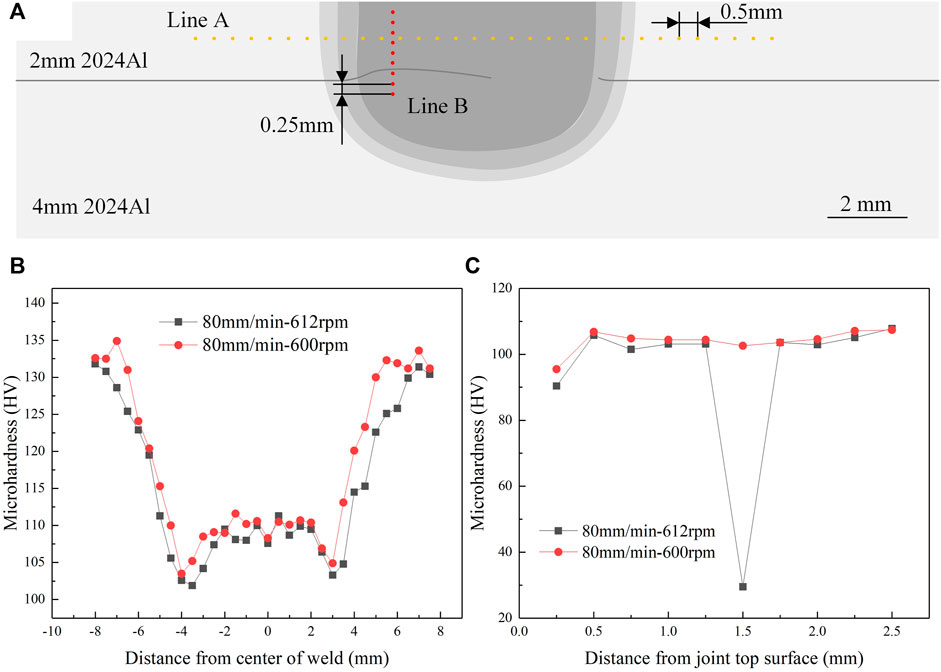
FIGURE 11. (A) Schematic of microhradness measurement locations; microhardness distributions of optimized and No. 5 joints: (B) parallel to the original lap interface and (C) perpendicular to the original lap interface.
As mentioned above, the welding temperature of the optimized joint is higher than that of the No. 5 joint. Therefore, the width of softening area of optimized joint is larger than that of No. 5 joint (Figure 11B). The average microhardness values of SZ in Figure 11B were calculated, and they are respectively 109.0 HV and 110.1 HV for the optimized and No. 5 joints. Compared with the No. 5 joint, the optimized joint has the SZ with smaller microhardness due to the larger gain size displayed in Figures 10C,D. By observing Figure 11C, it is known that the microhardness of SZ of optimized joint perpendicular to the original lap interface is also smaller than that of No. 5 joint. Because the cold lap is made up of pure Al, the measured point of SZ optimized joint which is located on the cold lap owns the very small microhardness value of 29.5 HV. From the experimental results in Figures 11B,C, it is concluded that the optimized joint owns lower the bearing capacity compared with the No. 5 joint, which is harmful to heightening the tensile strength of optimized joint obtained by N-KFSLW process.
Figure 12 presents the tensile strengths of 2024 Al alloys FSLW joints of this study and other reported references. It can be seen that after the optimization of welding tool and process parameters, the tensile strength of joints in this paper are significantly improved. Therein, the joint tensile strength of this study was calculated by dividing the tensile load by the thickness of upper sheet, and the value of reported reference was calculated by dividing the tensile load by the thickness of upper sheet and the ratio of specimen width and 35 mm. The joint tensile strength in this study is influenced by not only the height of cold lap of joint but also the microhardness of SZ. Generally speaking, lower cold lap height and higher microhardness are both beneficial to enhancing the tensile strength of FSLW joint. The height of cold lap of optimized joint is 15.9% lower than that of No. 5 joint, but the tensile strength (11.88 kN/mm) of optimized joint is only increased by 4.5% compared with that 11.37 kN/mm of No. 5 joint. The increased percentage in joint strength is smaller than that in joint EST, because the microhardness of SZ of optimized joint is smaller than that of No. 5 joint.
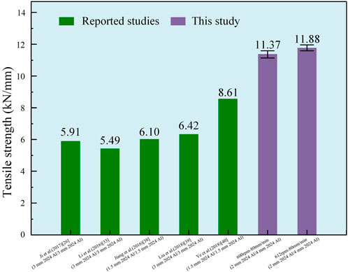
FIGURE 12. Tensile strengths of FSLW joints of this study and reported results.
For the N-KFSLW process in this study, the advantages on heightening the tensile strength of 2024 Al alloys lap joint originate from the welding tool including not only the stationary shoulder but also the upper half-thread pin. Therefore, the obtained thickness of SZ is nearly equal to that of upper sheet, and the height of cold lap is very small (Figures 9B,C). Under this condition, the joint by the upper half-thread pin (Table 5) has the tensile strength higher than 11 kN/mm, and this strength value is greatly higher than the strengths of FSLW joint reported by researchers (Jiang et al., 2016; Ji et al., 2017; Li et al., 2016; Liu et al., 2018; Ye et al., 2018). Certainly, based on the IPSO-RBF system, the optimized parameter combination is obtained and the corresponding tensile strength of 11.88 kN/mm is further improved.
The N-KFSLW technology was put forward to obtain the lap joint without keyhole through one-time process, and the 2024 Al alloys plates were chosen as the research object. In this paper, the IPSO algorithm was firstly proposed by increasing a new search method which was inspired by PIO algorithm. Moreover, the IPSO-RBF system was developed to maximize the strength of welding joint. The following conclusions were extracted.
1) The self-designed welding tool consisted of the outer stationary shoulder and the inner upper half-thread rotating pin. The stationary shoulder made the SZ have the thickness almost equal to the thickness of upper sheet, and the rotating pin made the cold lap have a very small height, thereby obtaining the joint with a high strength.
2) The new IPSO algorithm was developed by optimizing the PSO algorithm with PIO algorithm, which owned the advantages of larger convergence speed and stronger search ability compared with PSO algorithm. Eight kinds of benchmark functions were adopted to test and verify the excellent performance of IPSO algorithm.
3) The IPSO-RBF system was established to predict the joint strength and optimize the process parameters combination. Due to the advantages of IPSO algorithm, the prediction accuracy of IPSO-RBF system reached 1.7%, which was increased by 46.9% compared with that of PSO-RBF system.
4) The optimized parameters of welding speed, rotating speed and pin type optimized by the IPSO-RBF system were 612 rpm, 80 mm/min, and upper half-thread pin, respectively. The N-KFSLW joint tensile strength reached 11.88 kN/mm, which was 4.5% higher than the maximum strength before optimization. The high-strength lap joint after tensile test presented the tensile fracture mode.
The original contributions presented in the study are included in the article/Supplementary Material, further inquiries can be directed to the corresponding authors.
YL, ZS, XQ, PG, SJ, BW, and JZ contributed conception and design of the study. YL developed the IPSO-RBF system. Z.S. performed the N-KFSLW experiment. PG and SJ analyzed the experimental results. YL wrote the first draft of the manuscript. All authors contributed to manuscript revision, read, and approved the submitted version.
Author BW was employed by Qingdao Xindong Aviation Technology Development Co., LTD.
The remaining authors declare that the research was conducted in the absence of any commercial or financial relationships that could be construed as a potential conflict of interest.
All claims expressed in this article are solely those of the authors and do not necessarily represent those of their affiliated organizations, or those of the publisher, the editors and the reviewers. Any product that may be evaluated in this article, or claim that may be made by its manufacturer, is not guaranteed or endorsed by the publisher.
Asmael, M., Nasir, T., Zeeshan, Q., Safaei, B., Kalaf, O., Motallebzadeh, A., et al. (2022). Prediction of properties of friction stir spot welded joints of AA7075-T651/Ti-6Al-4V alloy using machine learning algorithms. Arch. Civ. Mech. Eng. 22 (2), 94. doi:10.1007/s43452-022-00411-x
Chanakyan, C., and Sivasankar, S. (2020). Parametric studies in friction stir welding on Al-Mg alloy with (HCHCr) tool by Taguchi based desirability function analysis (DFA). J. Ceram. Process. Res. 21 (6), 647–655. doi:10.36410/jcpr.2020.21.6.647
Chen, Z., Ales, S. K., Wang, L., Pasang, T., Lau, K. T., and Zhu, M. (2017). Effects of friction stir welding on corrosion behaviors of aa2024-T4 aluminum alloy. MATEC Web Conf. 109, 02003. doi:10.1051/matecconf/201710902003
Chien, C. H., Lin, W. B., and Chen, T. P. (2011). Optimal FSW process parameters for aluminum alloys AA5083. J. Chin. Inst. Eng. 34 (1), 99–105. doi:10.1080/02533839.2011.553024
Dong, J., Zhao, Y. X., and Liu, C. (2020). Constrained PSO based center selection for RBF networks under concurrent fault situation. Neural process. Lett. 51 (3), 2437–2451. doi:10.1007/s11063-020-10202-1
Du, B., Yang, X., Liu, K., Sun, Z., and Wang, D. (2019). Effects of supporting plate hole and welding force on weld formation and mechanical property of friction plug joints for AA2219-T87 friction stir welds. Weld. World 63 (4), 989–1000. doi:10.1007/s40194-019-00731-2
Glaissa, M. A. A., Asmael, M., and Zeeshan, Q. (2020). Recent applications of residual stress measurement techniques for FSW joints: A review. J. Kejuruter. 32 (3), 1–15. doi:10.17576/jkukm-2020-32(3)-01
Gong, M. Q., Sun, M. W., Huang, M., and Xiang, S. W. (2012). Prediction of cutting consumption based on optimization-making RBF artificial neural network. Adv. Mat. Res. 430-432, 659–663. doi:10.4028/www.scientific.net/AMR.430-432.659
Gong, P., Zuo, Y.-Y., Ji, S.-D., Yan, D.-J., Li, D.-C., and Shang, Z. (2021). Non-keyhole friction stir welding for 6061-T6 aluminum alloy. Acta Metall. Sin. 35 (5), 763–772. doi:10.1007/s40195-021-01289-z
Gong, P., Zuo, Y., Ji, S., Yan, D., and Shang, Z. (2022). A novel non-keyhole friction stir welding process. J. Manuf. Process. 73, 17–25. doi:10.1016/j.jmapro.2021.10.067
Huang, Y. X., Han, B., Tian, Y., Liu, H. J., Lv, S. X., Feng, J. C., et al. (2013). New technique of filling friction stir welding. Sci. Technol. Weld. Join. 16 (6), 497–501. doi:10.1179/1362171811y.0000000032
Ji, S., Li, Z., Zhou, Z., and Wu, B. (2017). Effect of thread and rotating speed on material flow behavior and mechanical properties of friction stir lap welding joints. J. Mat. Eng. Perform. 26 (10), 5085–5096. doi:10.1007/s11665-017-2928-8
Jiang, R. R., Li, W. Y., Yang, X. W., and Gao, D. L. (2016). Lapping process of non-pin friction stir welding of thin AA2024 aluminum alloy and joint performance. Trans. China Weld. Institution 37, 99–102. Chinese.
Kim, W.-k., Goo, B.-c., and Won, S.-t. (2010). Optimal design of friction stir welding process to improve tensile force of the joint of A6005 extrusion. Mater. Manuf. Process. 25 (7), 637–643. doi:10.1080/10426910903365745
Kumar, R., Pancholi, V., and Bharti, R. P. (2018). Material flow visualization and determination of strain rate during friction stir welding. J. Mater. Process. Technol. 255, 470–476. doi:10.1016/j.jmatprotec.2017.12.034
Li, Z., Yue, Y., Ji, S., Chai, P., and Zhou, Z. (2016). Joint features and mechanical properties of friction stir lap welded alclad 2024 aluminum alloy assisted by external stationary shoulder. Mater. Des. 90, 238–247. doi:10.1016/j.matdes.2015.10.056
Liang, J. J., Qin, A. K., Suganthan, P. N., and Baskar, S. (2006). Comprehensive learning particle swarm optimizer for global optimization of multimodal functions. IEEE Trans. Evol. Comput. 10 (3), 281–295. doi:10.1109/tevc.2005.857610
Liu, H., Zhao, Y., Hu, Y., Chen, S., and Lin, Z. (2015). Microstructural characteristics and mechanical properties of friction stir lap welding joint of Alclad 7B04-T74 aluminum alloy. Int. J. Adv. Manuf. Technol. 78 (9-12), 1415–1425. doi:10.1007/s00170-014-6718-2
Liu, H., Hu, Y., Peng, Y., Dou, C., and Wang, Z. (2016). The effect of interface defect on mechanical properties and its formation mechanism in friction stir lap welded joints of aluminum alloys. J. Mater. Process. Technol. 238, 244–254. doi:10.1016/j.jmatprotec.2016.06.029
Liu, Z., Zhou, Z., and Ji, S. (2018). Improving interface morphology and shear failure load of friction stir lap welding by changing material concentrated zone location. Int. J. Adv. Manuf. Technol. 95 (9-12), 4013–4022. doi:10.1007/s00170-017-1508-2
Medhi, T., Hussain, S. A., Roy, B. S., and Saha, S. C. (2021). An intelligent multi-objective framework for optimizing friction-stir welding process parameters. Appl. Soft Comput. 104, 107190. doi:10.1016/j.asoc.2021.107190
Meng, X., Cao, B., Qiu, Y., Chen, H., Xie, Y., Wan, L., et al. (2021a). Equal-load-bearing joining of alclad AA2024-T4 alloy stringers and skins in aviation via friction stir lap welding. J. Manuf. Process. 68, 1295–1302. doi:10.1016/j.jmapro.2021.06.043
Meng, X., Huang, Y., Cao, J., Shen, J., and dos Santos, J. F. (2021b). Recent progress on control strategies for inherent issues in friction stir welding. Prog. Mater. Sci. 115, 100706. doi:10.1016/j.pmatsci.2020.100706
Meng, X. C., Xie, Y. M., Ma, X. T., Liang, M. Y., Peng, X. Y., Han, S. W., et al. (2022). Towards friction stir remanufacturing of high-strength aluminum components. Acta Metall. Sin. doi:10.1007/s40195-022-01444-0
Mirjalili, S., Mirjalili, S. M., and Lewis, A. (2014). Grey wolf optimizer. Adv. Eng. Softw. 69, 46–61. doi:10.1016/j.advengsoft.2013.12.007
Nasir, T., Asmael, M., Zeeshan, Q., and Solyali, D. (2020). Applications of machine learning to friction stir welding process optimization. J. Kejuruter. 32 (2), 171–186. doi:10.17576/jkukm-2020-32(2)-01
Naumov, A. A., Isupov, F. Y., Golubev, Y. A., and Morozova, Y. N. (2019). Effect of the temperature of friction stir welding on the microstructure and mechanical properties of welded joints of an Al – Cu – Mg alloy. Mater. Sci. Heat. Treat. 60 (11-12), 695–700. doi:10.1007/s11041-019-00342-0
Patel, V., Li, W., Andersson, J., and Li, N. (2022). Enhancing grain refinement and corrosion behavior in AZ31B magnesium alloy via stationary shoulder friction stir processing. J. Mater. Res. Technol. 17, 3150–3156. doi:10.1016/j.jmrt.2022.02.059
Ren, M. L., Huang, X. D., Zhu, X. X., and Shao, L. J. (2020a). Optimized PSO algorithm based on the simplicial algorithm of fixed point theory. Appl. Intell. (Dordr). 50 (7), 2009–2024. doi:10.1007/s10489-020-01630-6
Ren, W., Xin, R., Tan, C., and Liu, D. (2020b). Texture related inhomogeneous deformation and fracture localization in friction-stir-welded magnesium alloys: A review. Front. Mat. 6, 339. doi:10.3389/fmats.2019.00339
Selvaraj, M., Murali, V., and Koteswara Rao, S. R. (2013). Mechanism of weld formation during friction stir welding of aluminum alloy. Mater. Manuf. Process. 28 (5), 595–600. doi:10.1080/10426914.2013.763956
Song, Q., Wang, H., Ji, S., Ma, Z., Jiang, W., and Chen, M. (2020). Improving joint quality of hybrid friction stir welded Al/Mg dissimilar alloys by RBFNN-GWO system. J. Manuf. Process. 59, 750–759. doi:10.1016/j.jmapro.2020.10.037
Soori, M., Asmael, M., and Solyali, D. (2021). Recent development in friction stir welding process: A review. SAE Int. J. Mat. Manf. 14 (1), 63–80. doi:10.4271/05-14-01-0006
Srinivasulu, M. (2021). Multi-lead ECG signal analysis using RBFNN-MSO algorithm. Int. J. Speech Technol. 24 (2), 341–350. doi:10.1007/s10772-021-09799-y
Sun, H., and Duan, H. B. (2014). "PID controller design based on prey-predator pigeon-inspired optimization algorithm", in: Proceedings of the 11th IEEE International Conference on Mechatronics and Automation (ICMA)), Kagawa, Japan, August, 2014, IEEE. 1416–1421. doi:10.1109/ICMA.2014.6885907
Sun, X., Cao, W., Qing, Z., Cheng, E., and Bian, J. (2016). "A method for predicting ultimate bearing capacity of bolts based on PSO-RBF neural network", in: Proceedings of the 2016 International Conference on Computational Intelligence and Applications (ICCIA).).Jeju, South Korea, August, 2016, IEEE. doi:10.1109/ICCIA.2016.16
Tian, D. A. N., Zhou, C.-J., and He, J.-H. (2019). Hall–Petch effect and inverse Hall–petch effect: A fractal unification. Fractals 26 (06), 1850083. doi:10.1142/s0218348x18500834
Venkateswarlu, D., Mandal, N. R., Mahapatra, M. M., and Harsh, S. P. (2013). Tool design effects for FSW of AA7039. Weld. J. 92 (2), S41–S47.
Wan, L., and Huang, Y. (2017). Microstructure and mechanical properties of Al/steel friction stir lap weld. Metals 7 (12), 542. doi:10.3390/met7120542
Wang, K., Wu, B., Qiao, K., Wang, H., Peng, P., Han, P., et al. (2020). Microstructure and mechanical properties of friction stir lap welded dissimilar zirconium-steel joint. J. Mater. Res. Technol. 9 (6), 15087–15093. doi:10.1016/j.jmrt.2020.10.099
Wu, H., Chen, Y.-C., Strong, D., and Prangnell, P. (2015). Stationary shoulder FSW for joining high strength aluminum alloys. J. Mater. Process. Technol. 221, 187–196. doi:10.1016/j.jmatprotec.2015.02.015
Xiao, X., Qin, D. Q., Mao, Y., and Fu, L. (2021). Effects of pin morphology on the interface defects of the FSWed lap joints of 2A12 aluminum alloy. J. Manuf. Process. 68, 128–140. doi:10.1016/j.jmapro.2021.05.023
Xie, Y. M., Meng, X. C., Chang, Y. X., Mao, D. X., Qin, Z. W., Wan, L., et al. (2022). Heteroatom modification enhances corrosion durability in high-mechanical-performance graphene-reinforced aluminum matrix composites. Adv. Sci. 9 (23), 2104464. doi:10.1002/advs.202104464
Ye, J. H., Liu, X. S., and Wang, S. H. (2018). Friction stir lap welding force of 2024-T4 aluminum alloy without penetrating upper plate impact of learning performance. Trans. China Weld. Institution 39 (2), 71–74. Chinese.
Yin, R. W., Li, Q. Y., Li, P. C., and Lu, D. T. (2020). Parameter identification of multistage fracturing horizontal well based on PSO-RBF neural network. Sci. Program. 2020, 1–11. doi:10.1155/2020/6810903
Yu, M. C., Li, G. F., Jiang, D., Jiang, G. Z., Zeng, F., Zhao, H. Y., et al. (2020). Application of PSO-RBF neural network in gesture recognition of continuous surface EMG signals. J. Intelligent Fuzzy Syst. 38 (3), 2469–2480. doi:10.3233/jifs-179535
Zhao, H., Wang, Y., Dong, J., Wen, Q., Gong, P., and Yue, Y. (2021). Eliminating keyhole by ultrasonic-assisted passive filling friction stir repairing process. Trans. Indian Inst. Mater. 74 (6), 1501–1508. doi:10.1007/s12666-021-02238-1
Keywords: non-keyhole friction stir lap welding, 2024 aluminum alloy, IPSO-RBF system, upper half-thread pin, tensile strength
Citation: Li Y, Sun Z, Qi X, Gong P, Ji S, Wang B, Zhang Z and Zhang J (2022) Improving the tensile strength of non-keyhole friction stir lap welding joint of 2024-T4 Al alloy by radial basis function neural network and improved particle swarm optimization algorithm. Front. Mater. 9:1039580. doi: 10.3389/fmats.2022.1039580
Received: 08 September 2022; Accepted: 03 October 2022;
Published: 20 October 2022.
Edited by:
Mingyi Zheng, Harbin Institute of Technology, ChinaReviewed by:
Jacek Tomków, Gdansk University of Technology, PolandCopyright © 2022 Li, Sun, Qi, Gong, Ji, Wang, Zhang and Zhang. This is an open-access article distributed under the terms of the Creative Commons Attribution License (CC BY). The use, distribution or reproduction in other forums is permitted, provided the original author(s) and the copyright owner(s) are credited and that the original publication in this journal is cited, in accordance with accepted academic practice. No use, distribution or reproduction is permitted which does not comply with these terms.
*Correspondence: Peng Gong, R29uZ3BlbmcyMDIwQDE2My5jb20=; Shude Ji, c3VwZXJqc2RAMTYzLmNvbQ==
†These authors have contributed equally to this work and share first authorship
Disclaimer: All claims expressed in this article are solely those of the authors and do not necessarily represent those of their affiliated organizations, or those of the publisher, the editors and the reviewers. Any product that may be evaluated in this article or claim that may be made by its manufacturer is not guaranteed or endorsed by the publisher.
Research integrity at Frontiers
Learn more about the work of our research integrity team to safeguard the quality of each article we publish.