 Mingfu Wen
 Yueqian Du
 Runduo Liu
 Xiaodong Niu
95% of researchers rate our articles as excellent or good
Learn more about the work of our research integrity team to safeguard the quality of each article we publish.
Find out more
ORIGINAL RESEARCH article
Front. Mater. , 03 November 2022
Sec. Smart Materials
Volume 9 - 2022 | https://doi.org/10.3389/fmats.2022.1034127
This article is part of the Research Topic Characterization and Application of Magneto-sensitive Soft Materials View all 20 articles
Magnetorheological fluids (MRFs) are a class of smart magnetic controlled materials whose rheological properties can be controlled by a magnetic field. These materials have advantages of short response time, high dynamic range and low energy consumption. Due to their excellent properties, MRFs have a widely application potential in the field of impact mitigation. As the shear rate dependent viscosity of MRFs is astonishing for the shear thinning effect, thus it is crucial to study the rheological properties cross a wide range of shear rates for guiding the design and application of MRFs based adaptive impact absorbers. Commercial rotational rheometers are usually used to test the rheological properties of MRFs, but their range of measuring shear rates are limited. Commercial capillary rheometers are designed to measure the rheological behavior over a wide range of shear rates, but they’re usually lack of ability to measure with magnetic field. In order to study the rheological properties of MRFs under higher shear rate and applied magnetic field, a lab-made speed-controlled capillary magneto-rheometer is developed in the presnt work; The expressions for equivalent shear rate and apparent viscosity of MRFs under the dimensional constraint of the set-up are derived. In addition, the theoretical expression of shear rate of MRFs is modified by Rabinowitsch correction. Then, the rheological properties of three particle volume fractions (10%, 15%, and 20%)of MRFs with different magnetic field strengths (6 mT, 13 mT, 20 mT, and 25 mT)are tested and analyzed, and the rheological characteristic curves of MRFs with shear rate range of
Magnetorheological fluids (MRFs) are a class of smart materials composed of micro soft ferromagnetic or paramagnetic particles dispersed in a carrier fluid, whose rheological properties can be controlled when stimulated with magnetic field (Rabinow., 1948; Kolekar et al., 2014; Kamble et al., 2015). When there is no external magnetic field, it exhibits like a Newtonian fluid with low viscosity. However, under the application of an external magnetic field, it exhibits like a Non-Newtonian fluid, and phase changes from a free-flowing liquid to a semi-solid or even a solid in a milliseconds level time, showing strong controllable rheological characteristics. This phenomenon is characterized by low energy consumption, easy control, reversible and rapid response (Carlson et al., 1996). Based on the above advantages, MRFs have attracted the research attention of many scholars in the field of impact mitigation applications over a large range of shear rate. Therefore, the study on the rheological characteristics of MRFs has a great guiding significance in device design and engineering application (Yang et al., 2002).
Rotational rheometers (Becnel et al., 2014) and capillary rheometers (Allebrandi et al., 2019) are usually used to measure the rheological properties of polymers. The rotational rheometers are the most widely used type of rheometer, which are used to measure the rheological properties of fluids at low shear rates. The capillary rheometers are used to measure the shear viscosity at high shear rates. It is divided into speed-controlled and pressure-controlled. The maximum shear rate of commercial rotational rheometers is usually below
In this paper, a lab-made speed-controlled capillary magneto-rheometer was developed for rheological characterization of MRFs. It was utilized for testing the rheological properties of MRF prepared with different volume fractions and stimulated with different magnetic fields over a shear rates range from
A capillary magneto-rheometer proposed for characterizing the rheological properties of MRFs over a large range of shear rates and a lab-made prototype was built and employed in the experiments. The structure of the capillary channel can be simplified as shown in Figure 1.

FIGURE 1. Geometric structure of capillary flow.
The following five assumptions are made before deducing the equation of capillary rheological properties:
(1) Unidirectional shear;
(2) Laminar flow (no bubbles are produced during the flow);
(3) Wall adherence;
(4) Isothermal flow;
(5) Incompressible flow.
As shown in Figure 1, the Navier-Stokes equation (N-S equation) for the viscous fluid in the laminar flow inside a horizontal straight circular pipe with uniform pipe diameter is:
where
For a horizontal circular tube, the force of gravity on the fluid can be ignored and only the axial velocity is considered. By assuming that the continuity equation is satisfied, the pressure difference between two ends is constant and the fluid moves steadily, then the N-S equation can be simplified as:
According to the selected column coordinate system, z is the axial coordinate, r is the radial coordinate, then:
Figure 2 shows the distribution of pressure, velocity and shear force in the longitudinal cross profile of the pipeline. According to the boundary conditions and initial conditions, the integral of the above equation gives the following velocity profile:
Where
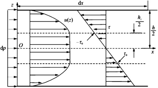
FIGURE 2. Flow velocity and shear force distribution of MRFs in pipeline interface.
With Eq 4, the quantitative relationships among volume flow Q, aspect ratio of pipe, outlet and inlet pressure difference, viscosity and shear rate can be described by Poiseuille’s law:
According to the principle of pipe geometry and fluid mechanics, the shear rate at the wall is then calculated as:
and the shear force at the corresponding wall is given by:
Where D is the diameter of capillary tube.
Finally, according to the shear force and shear rate, the apparent viscosity can be described as:
Considering the actual geometry of the capillary tube and working conditions of magneto-rheometer, it is necessary to modify the calculation models to get the more accurate shear rate. Therefore, Rabinowitsch should be applied for the flow model, and reliable viscosity data can be obtained when these corrections are applied.
The Rabinowitsch correction:
where
In order to validate the Rabinowitsch correction for the shear rates in capillary tube, a finite element simulation of capillary flow based on COMSOL Multiphysics was conducted. The comparison of the shear rates estimated in different methods are shown in Table 1. In the simulations, the shear rates in first column were calculated from the given inlet flow rate using Eq 6, the shear rates in second column were calculated from the given inlet flow rate using the Rabinowitsch correction Eq 9, and the shear rates in third column were calculated from the outlet flow rate using Eq 6. According to the comparison results, it can be obtained that the accuracy of shear rates estimated after Rabinowitsch correction have been improved significantly.
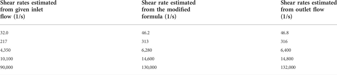
TABLE 1. Comparison of the shear rates estimated in different methods.
In this paper, the theoretical magnetic response viscosity of MRFs with different magnetic field stimulations are calculated based on the theoretical equation.
The viscosity of particle suspension can be obtained by Einstein equation (Vand, 1945):
where
where b and c are the coefficients identified under test. According to the fitting calculation,
In the presence of an applied magnetic field, the increment of the magnetic response viscosity of MRFs relative to the zero-field viscosity can be calculated by the following equation; (Chen, 2007; Zuo, 2018):
according to the Langevin function:
the expression of magnetic response viscosity is simplified as follows:
where
In order to describe the rheological properties of MRFs under high shear rate, a speed-controlled capillary rheometer was developed in this paper. The capillary rheometer is available to measure the apparent viscosity of materials in a wide range of shear rates by adjusting the capillary diameter and pressure/velocity in testing and studying the rheological properties of MRFs. The capillary tube can be divided into three parts: entrance development channel, damping channel and exit channel. In order to generate a completely laminar flow and reduce the influence of the inlet on pressure measurement, an injection inlet of the MRFs was utilized at the entrance channel and the measuring position is located in the damping channel of the rheometer. Generally, a magnetic field is applied in this section of the pipeline and a pressure sensor is installed; The outlet channel is used to drain the MRFs and recover it. The flow medium to be measured is injected into the capillary tube at different speeds under different magnetic field excitations to form a certain range of shear rate (
The lab-made speed-controlled capillary magneto-rheometer mainly consists of four systems: Drive system, control system, data acquisition system and MRFs collection system. The construction scheme of the experimental set-up is shown in Figure 3:
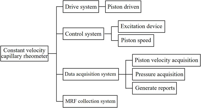
FIGURE 3. Principle structure block diagram of lab-made speed-controlled capillary rheometer.
The composition of the control system is shown in Figure 4, including PC, motion control card, servo driver and servo cylinder. Both control and data acquisition systems are achieved by programming with Labview. The PC side is connected with network cable, programmed with LabView, and handled the motion control card by calling the dynamic link library DLL function; The LHEM-2424-4PD-00 motion control card is adopted, which is equipped with network cable interface, USB interface and RS485 serial port. It has 24 IO input ports and 16 IO output ports, and it is able to carry out 4-axis operation control at the same time; ASD620B series Servo driver was adopted which can be used for speed control, position control and torque control; The model of servo motor with the ability of self-locking is 80ST-M02430A-N, whose maximum speed and minimum speed are 5,000 r/min and 1r/min, respectively. The power supply is controlled by the servo driver, and the motor rotation angle is recorded by the encoder. The motor shaft is connected to an electric cylinder, which converts rotational motion into linear motion and pushes the needle piston into injection.
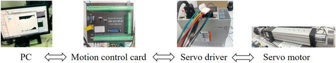
FIGURE 4. Composition of control system.
The composition of the data acquisition system is shown in Figure 5, which includes pressure sensors on both sides of the pipeline, flowmeters, and NI data acquisition cards. The data acquisition card collects the voltage and pulse signal of the sensors, reads the signal in the Labview control panel and outputs with data table.Two pipe pressure sensors and a ring pressure sensor are used in this experimental system. Two pipeline pressure sensors are Aier AE-S series micro high-frequency dynamic pressure transmitters, with a range of 0–3.5 and 0–40 MPa, with an accuracy of ±0.25% of full scale. The annular pressure sensor is installed at the end of the push rod of the electric cylinder to measure the thrust of the push rod. The pressure measurement range is 30 KN and the measurement accuracy is ± 0.05%. The flowmeter is a small flow elliptical gear flowmeter, whose measurement range is 0.5–150 ml/min with a measurement accuracy of 0.2%. A Helmholtz coil is used to provide a stable magnetic field for the experiments. The Helmholtz coil has a cylindrical region with a height range of 0.8R and a radius range of 0.3R.
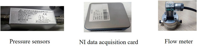
FIGURE 5. Composition of data acquisition.
Using a programmed DC power supply with a maximum output voltage of 24 V, the magnetic field strength at the center of the Helmholtz coil is measured with a gaussmeter, and the variation curve of the magnetic field strength with the output voltage of the power supply is shown in Figure 6:
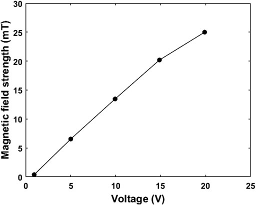
FIGURE 6. The magnetic field strength of Helmholtz coil varies with the output voltage of power supply.
The four voltages selected for the experiment are 5, 10, 15, and 20 V, and the corresponding magnetic field strengths are 6, 13, 20, and 25 mT, respectively. The Helmholtz coils are arranged on both sides of the capillary tube, and a uniform magnetic field perpendicular to the pipe axis is applied to the capillary tube. The structure diagram and physical diagram of the lab-made capillary rheometer set-up finally built are shown in Figure 7 and Figure 8:
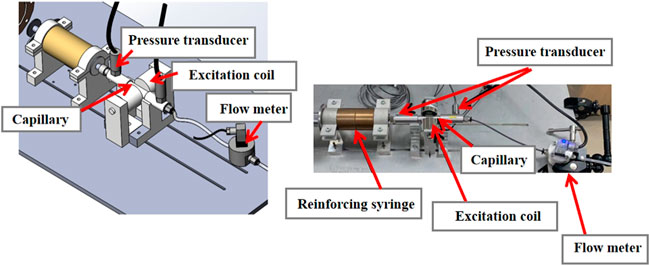
FIGURE 7. Structure diagram of lab-made speed-controlled capillary rheometer.
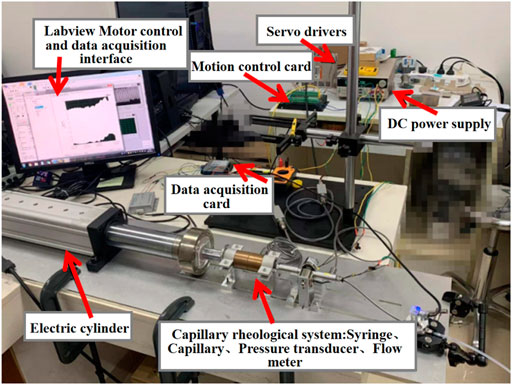
FIGURE 8. Physical picture of the test set-up.
The given viscosity of a pure silicone oil and its measured viscosity using commercial rotary viscometer (SNB-2 Digital viscometer) are taken to compare for calibrating the lab-made capillary rheometer. Considering the given viscosity as standard, the corresponding mearsuring errors of the commercial rotary viscometer and the lab-made capillary rheometer were evaluated as shown in Table 2.
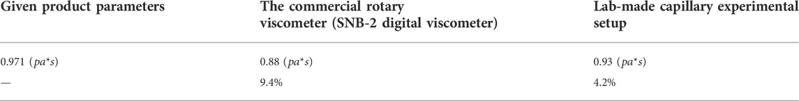
TABLE 2. Comparison of the viscosities obtained in different methods.
According to the comparison shown in Table 2, it can be obtained that the relative error measured by the commercial viscometer is 9.4% while the relative error measured by the lab-made capillary magneto-rheometer is 4.2%. Thus, the experimental data in the following subsections of this paper are all measured with the lab-made magneto-rheometer. The rheological properties of pure silicone oils were tested using the lab-made capillary rheometer at different shear rates, and the measured curves between shear stress and shear rate were obtained as shown in Figure 9. It can be seen that the relationship between shear stress and shear rate is linear, which satisfies the constant viscosity of pure silicone oil as a Newtonian fluid.
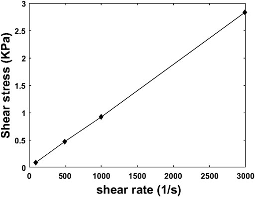
FIGURE 9. Relationship between shear stress and shear rate of silicone oil measured by the custom capillary rheometer.
In order to study the magnetorheological properties of MRFs over a large range of shear rate under magnetic field stimulation, a lab-made capillary magneto-rheometer is developed. The influence of different particle volume fraction and different magnetic fields on the rheological properties of MRFs over a large range of shear rate are experimentally studied. Among them, the selected MRF particle size is
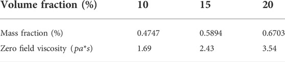
TABLE 3. Mass fraction and zero field viscosity values of MRF with different volume fractions.
In the experiments, the calculated mass fraction values and measured zero field viscosity of MRFs with different volume fractions are also shown in Table 3.
In the experiments, the lab-made speed-controlled rheometer is employed to measure the pressure drop and flow rate at both ends of the capillary, and MRFs are prepared with different particle volume fractions. The shear force and viscosity are calculated by the pressure drop, flow rate and geometric dimension using the method described in Eq 7 and Eq 8. The effects of particle volume fraction and magnetic field excitation on the rheological characteristics of MRFs are experimentally studied.
When the tube flow rate is limited, the capillary with a smaller diameter should be chosen in order to achieve the shear rate
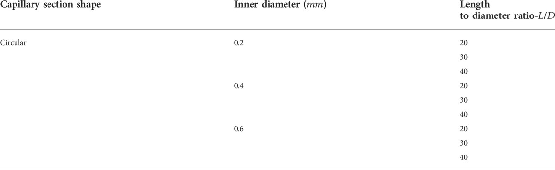
TABLE 4. The inner diameter and aspect ratio of the capillary used in the experiments.
In the experiments, the pipeline pressure signals are collected and converted to obtain the pressure drop at steady state. The curves of shear stress and viscosity considering various influences (shear rate, volume fraction, magnetic field strength) were obtained experimentally. According to the geometry of capillary tube and fluid mechanics, the shear rate at the wall is determined with Eq 6.
In Figure 10, it is found that the internal pressure of the pipeline is too large for crystal tube when the shear rate exceeds

FIGURE 10. Relationship between mean velocity and theoretical apparent shear rate of capillary tubes with different inner diameters.
In order to describe the overall rheological characteristics of MRFs under the magnetic field stimulation over a large range of shear rate, an MR Fluids samlpe with volume fraction of 20% was prepared and tested under magnetic field of 25 mT and the rheological characteristic curve was obtained, as shown in Figure 10.
It can be seen from Figure 11 the apparent viscosity curve shows an obvious shear thinning phenomenon over
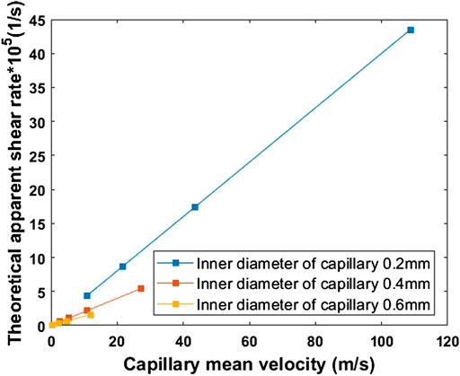
FIGURE 11. Apparent viscosity as a function of shear rate.
The effects of the apparent viscosity in the non-Newtonian flow are usually described by the dimensionless Mason number (Sherman et al., 2015), which represents the relationship between fluid force
where
When Mason number is used to normalize rheological curves, the following equation from can be used to fit the data (Becnel et al., 2015).
where
(1) Volume fraction
To investigate the effect of the volume fraction of MRFs on its rheological properties with a shear rate range over

FIGURE 12. (A) The apparent viscosity versus apparent shear rate curves with different volume fraction under a magnetic field strength of 25 mT; (B) Apparent viscosity versus Mason number curves.
It can be seen from Figure 12A, the phenomenon of shear thinning of magnetorheological fluid with different volume fractions appeared obviously. In specific, the shear thinning phenomenon is more obvious with the increase of particle volume fraction and this phenomenon is reduced when the shear rate higher than 4,000 s−1. Under the same shear rate and magnetic field strength excitations, the larger the volume fraction, the higher the apparent viscosity.
The normalized apparent viscosity of MRFs with different volume fractions were calculated using Eq 16 and the Mason number of MRFs with different volume fractions were calculated using Eq 15. As shown in Figure 12B, the normalized rheological characteristic curve is obtained. It can be seen that under the same magnetic field, the rheological characteristics of MRFs with different volume fractions keep the same trend and they’re all approaching the formula fitting curve (
(2) Magnetic field intensity
In order to study the effect of the magnetic field intensity of MRFs on its rheological properties with a shear rate range of
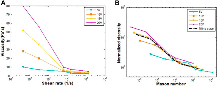
FIGURE 13. (A) The apparent viscosity versus apparent shear rate curves with different magnetic field intensities for 20% volume fraction MRFs; (B) Apparent viscosity versus Mason number curve.
It can be seen from Figure 13A that when the samples are prepared with the same particle volume fraction and measured under the same shear rate, the greater the magnetic field strength, the higher the apparent viscosity; Under the condition of the same particle volume fraction, with the increase of shear rate, the apparent viscosity is lower, and the shear thinning phenomenon is more obvious with the increase of coil voltage. It is consistent with the conclusion of related field research.
In Figures 13A,B normalized characterization based on Mason number is conducted. The results show that the apparent viscosity curves obtained under different magnetic field intensities shrink to a master rheological curve. This feature allows us to reduce the number of tests in experiments, and it can be detected if one of the tests has abnormal error.
In order to study the rheological properties of MRFs within a wide shear rate range, a speed-controlled capillary magneto-rheometer is developed. The rheological properties of MRF over the shear rate range of
The original contributions presented in the study are included in the article/Supplementary Material, further inquiries can be directed to the corresponding authors.
MW and XN contributed to conception of the study. MW, YD, and ZL organized the discussion and drafting. MW, ZL, and HX designed the experimental apparatus and took charge of the fabrication. RL, YD, LR, and YO conducted the modeling and experimental verification. YD wrote the first draft of the manuscript. MW and XN revised the manuscript and made the corrections. All authors contributed to manuscript revision, read, and approved the submitted version.
This research was supported by the STU Scientific Research Foundation (NTF20010, NTF19045) and the National Natural Science Foundation of China (NO. 12172203).
The authors declare that the research was conducted in the absence of any commercial or financial relationships that could be construed as a potential conflict of interest.
All claims expressed in this article are solely those of the authors and do not necessarily represent those of their affiliated organizations, or those of the publisher, the editors and the reviewers. Any product that may be evaluated in this article, or claim that may be made by its manufacturer, is not guaranteed or endorsed by the publisher.
Allebrandi, S. M., Van Ostayen, R. A. J., and Lampaert, S. G. E. (2019). Capillary rheometer for magnetic fluids. J. Micromech. Microeng. 30 (1), 015002. doi:10.1088/1361-6439/ab3f4c
Becnel, A. C., Hu, W., and Wereley, N. M. (2014). Mason number analysis of a magnetorheological fluid-based rotary energy absorber. IEEE Trans. Magn. 50 (11), 1–4. doi:10.1109/tmag.2014.2327634
Becnel, A. C., Sherman, S., Hu, W., and Wereley, N. M. (2015). Nondimensional scaling of magnetorheological rotary shear mode devices using the Mason number. J. Magnetism Magnetic Mater. 380, 90–97. doi:10.1016/j.jmmm.2014.10.049
Carlson, J. D., Catanzarite, D. M., and St. Clair, K. A. (1996). Commercial magneto-rheological fluid devices. Int. J. Mod. Phys. B 10, 2857–2865. doi:10.1142/s0217979296001306
Chi, C. Q., and Wang, Z. S. (1993). Ferrofluid dynamics. Beijing: Beijing University of Aeronautics and Astronautics Press (in Chinese).
Chen, M. (2018). Numerical and experimental study of fluid-structure interference and enhanced heat transfer in MHD. Shantou, China: Shantou University.
Chen, W. (2007). Study on magnetorheological fluid for damping control of linear motor. Guangzhou, China: Guangdong University of Technology. (in Chinese).
Daniele, T., Gaetano, D., Salvatore, C., Ernesto, D., Nino, G., and Maffettone, P. L. (2021). A microcapillary rheometer for microliter sized polymer characterization. Polym. Test. 102, 107332. doi:10.1016/J.POLYMERTESTING.2021.107332
Goncalves, F. D., and Ahmadian, M. (2005). A study on MR fluids subjected to high shear rates and high velocities. Proc. Spie 5760, 46–56. doi:10.1117/12.598530
Hu, W., and Wereley, N. M. (2011). Behavior of mr fluids at high shear rate. Int. J. Mod. Phys. B 25 (07), 979–985. doi:10.1142/S0217979211058535
Jha, S., and P, V. R. (2015). Design of parallel plate magnetorheometer for evaluating properties of magnetorheological polishing fluid. Mater. Today Proc. 2, 3251–3259. doi:10.1016/j.matpr.2015.07.134
Kamble, V. G., Kolekar, S., and Madivalar, C. (2015). Preparation of magnetorheological fluids using different carriers and detailed study on their properties. Am. J. Nanotechnol. 6 (1), 7. doi:10.3844/ajnsp.2015.7.15
Kang, L., Luo, Y., and Liu, Y. (2017). Testing device for rheological properties of magnetorheological fluid at high shear rate. J. Fail. Anal. Preven. 17 (3), 563–570. doi:10.1007/s11668-017-0277-4
Klingenberg, D. J., Ulicny, J. C., and Golden, M. A. (2007). Mason numbers for magnetorheology. J. Rheology 51 (5), 883–893. doi:10.1122/1.2764089
Kolekar, S. (2014). Preparation of magnetorheological fluid and study on its rheological properties. Int. J. Nanosci. 13 (02), 1450009. doi:10.1142/s0219581x14500094
Pieper, S., and Schmid, H. J. (2016). Guard ring induced distortion of the steady velocity profile in a parallel plate rheometer. Appl. Rheol. 26 (6), 18–24. doi:10.3933/applrheol-26-64533
Powell, L. A., Hu, W., and Wereley, N. M. (2013). Magnetorheological fluid composites synthesized for helicopter landing gear applications. J. Intelligent Material Syst. Struct. 24, 1043–1048. doi:10.1177/1045389X13476153
Rabinow, J. (1948). The magnetic fluid clutch. Trans. Am. Inst. Electr. Eng. 67, 1308–1315. doi:10.1109/T-AIEE.1948.5059821
Ruiz-López, J. A., Hidalgo-Alvarez, R., and De. Vicente, J. (2017). Towards a universal master curve in magnetorheology. Smart Mat. Struct. 26 (5), 054001. doi:10.1088/1361-665x/aa6648
Sherman, S. G., Becnel, A. C., and Wereley, N. M. (2015). Relating Mason number to Bingham number in magnetorheological fluids. J. Magnetism Magnetic Mater. 380, 98–104. doi:10.1016/j.jmmm.2014.11.010
Tammaro, D., D'Avino, G., Costanzo, S., Di Maio, E., Grizzuti, N., and Maffettone, P. L. (2021). A microcapillary rheometer for microliter sized polymer characterization. Polymer Testing 102, 107332.
Vand, V. (1945). Theory of viscosity of suspensions rigid spheres. Nature 155, 364–365. doi:10.1038/155364b0
Yang, G., Spencer, B. F., Carlson, J. D., and Sain, M. K. (2002). Large-scale MR fluid dampers: Modeling and dynamic performance considerations. Eng. Struct. 24 (3), 309–323. doi:10.1016/s0141-0296(01)00097-9
Keywords: magnetorheological fluids, capillary magneto-rheometer, high shear rate, viscosity, mason number
Citation: Wen M, Du Y, Liu R, Li Z, Rao L, Xiao H, Ouyang Y and Niu X (2022) Characterization of magnetorheological fluids based on capillary magneto-rheometer. Front. Mater. 9:1034127. doi: 10.3389/fmats.2022.1034127
Received: 01 September 2022; Accepted: 21 October 2022;
Published: 03 November 2022.
Edited by:
Xinglong Gong, University of Science and Technology of China, ChinaReviewed by:
Xian-Xu Bai, Hefei University of Technology, ChinaCopyright © 2022 Wen, Du, Liu, Li, Rao, Xiao, Ouyang and Niu. This is an open-access article distributed under the terms of the Creative Commons Attribution License (CC BY). The use, distribution or reproduction in other forums is permitted, provided the original author(s) and the copyright owner(s) are credited and that the original publication in this journal is cited, in accordance with accepted academic practice. No use, distribution or reproduction is permitted which does not comply with these terms.
*Correspondence: Mingfu Wen, bWZ3ZW5Ac3R1LmVkdS5jbg==; Xiaodong Niu, eGRuaXVAc3R1LmVkdS5jbg==
Disclaimer: All claims expressed in this article are solely those of the authors and do not necessarily represent those of their affiliated organizations, or those of the publisher, the editors and the reviewers. Any product that may be evaluated in this article or claim that may be made by its manufacturer is not guaranteed or endorsed by the publisher.
Research integrity at Frontiers
Learn more about the work of our research integrity team to safeguard the quality of each article we publish.