- 1School of Mechatronic and Automation Engineering, Shanghai University, Shanghai, China
- 2School of Communication and Information Engineering, Shanghai University, Shanghai, China
- 3School of Engineering and Informatics, University of Sussex, Brighton, United Kingdom
Acoustic metasurfaces have been increasingly explored in the past 10 years because of their compact structure and wave manipulation capabilities. In this work, we explore the feasibility of using an acoustic metasurface lens (MSL) for the characterization of near surface defects in NDT. First, we delimited the design space for a MSL operating at 100 kHz, in terms of spatial footprint and materials, and then realized a library of labyrinthine cells optimized for transmission. Then, we assembled the unit cells into lens and simulated its performance in a hole inspection process. The time-domain simulations predicted an increase in scattering and interface effects but, thanks to the focusing behavior, they also showed a much lower drop in the peak amplitude (20%, compared to 70% without MSL). Finally, we validated the simulations using a UTR9000-based MSL on an acrylic sample. Experiments with the MSL showed a converging energy profile, reduced to half of its width without the lens, and the presence of additional transmission peaks allowed to determine the defect diameter with excellent precision, thus circumventing near surface interference. Our study may be the first step towards flexible beam control systems based on a single transducer.
Introduction
Near surface defects occur widely during machining processes (Jawahir et al., 2011; Zenia et al., 2015), consolidation (Kalore et al., 2019), cyclic friction (Al-Tameemi et al., 2018), etc. They are detrimental to mechanical properties and eventually shorten the service life of products. Near surface defect inspection has thus attracted growing interest in nondestructive testing/evaluation (NDT/E) and structural health monitoring (SHM). Various methods have been proposed for inspecting this type of defects. For example, eddy currents have been used to inspect buried defects up to 4 mm, even when they were masked by the presence of the rivets in aeronautical lap joints (Joubert et al., 2010). Lock-in thermography has been used to visualize subsurface defects located at a depth of less than 2 mm in carbon fiber reinforced plastics in 3D (Liu et al., 2015).
Ultrasonic inspection is an efficient method with relatively low cost and high flexibility compared to other methods. In general, however, its use for the detection of near surface defects is hindered by the presence of constructive and destructive interference (due to the surface) and by electronic transmission noise, which is stronger for the first peaks detected (i.e. the “early arrivals”). It is thus hard to directly characterize near surface defects using bulk waves. Surface waves have long been explored for surface and subsurface defects. For example, Resch et al. have applied Rayleigh waves for monitoring small surface fatigue crack growth, in the direction normal to the surface, by looking at the reflection coefficient under the long wavelength hypothesis (crack depth << wavelength) (Resch et al., 1985). With a similar methodology, Koester et al. used a 15 MHz point focused transducer in an immersion system for artificial subsurface defect imaging in bearings (Koester et al., 2012). Multi-frequency ultrasonic inspection ranging from 7.5 MHz to 15 MHz was also tested for inclusion and fatigue life evaluation (Turner et al., 2015) with different penetration depths from 200 μm to 400 μm. In thin plate structures, Lamb waves dominate and can be applied for defect inspection. For example, the best resolution of 5 mm at around 1 MHz was claimed for aluminum plates containing multiple defects using mode conversion and amplitude enhancement (Clough and Edwards, 2015). Recently, phased arrays have become popular thanks to their superior beam steering and full field imaging capabilities. Plausible subsurface imaging of holes with 0.5 mm in diameter at depths between 0.5 mm and 2 mm from the surface has been realized in a composite sample at 5 MHz using Green’s function recovery (Potter et al., 2018). But the depth difference of each hole cannot be precisely determined yet.
In addition to the methodologies using surface waves and phased arrays, metamaterial assisted inspection is also becoming popular, thanks to the rapid advancement of additive manufacturing. Metamaterials are normal materials (e.g., wood, plastic, metal), but engineered at subwavelength scale to have extremely beneficial properties. They have been used in fascinating applications in sectors like electromagnetic and mechanics since the early 2000s (Askari et al., 2020). In acoustics, metamaterials can help in bridging impedance mismatch (Li et al., 2017), realizing an acoustic cloak (Zigoneanu et al., 2014), enabling wavefront steering (Chen et al., 2021) and managing noise reduction (Melnikov et al., 2020). Furthermore, more compact acoustic systems can be achieved by metasurfaces (Li and M.Assouar, 2016; Memoli et al., 2017; Chen et al., 2019), which have a thickness smaller than the wavelength in the direction of propagation. Concerning the NDE/SHM of solid materials, the elastic wave containing various modes (longitudinal wave, shear wave, Lamb wave, etc…) should be carefully considered (Chen et al., 2022). Metasurfaces have been used to amplify the harmonics generated by defect related nonlinearities (Gliozzi et al., 2015), or, as a selective filter, to facilitate the propagation of A0 or S0 mode, thus preventing trivial signal post-processing (Tian and Shen, 2020). Based on longitudinal mode, Li et al. have designed a cone structured broadband matching layer with a continuous equivalent acoustic impedance from 11.4 MRyals to 3.0 MRayls (Li et al., 2017). Their cone was created through etching and precise cutting. The -6 db bandwidth was 100% for the designed structure and 52% for a quarter wavelength matching layer at 4 MHz.
A traditional transducer only possesses temporal resolution, but an additional metamaterial lens could impart spatial resolution to it. This is why different researchers have looked at focused metasurfaces. For instance, Xie et al. have designed Luneberg lenses for airborne ultrasonic frequency at 40 kHz and 8 kHz with the gradient refractive index (GRIN) type (Xie et al., 2018) while Tol et al. have explored a 3D-printed GRIN phononic crystal lens to focus A0 mode Lamb waves and achieving three times the enhanced energy harvesting capability (Tol et al., 2019). A few work has also demonstrated the inspection possibility by integrating metamaterials with commercial transducers. Thippeswamy et al. achieved focal behavior with a structure made of concentric shells added on a conventional transducer, where the number of shells could be increased to improve the focusing accuracy (Thippeswamy et al., 2021). In this latter case, the maximum and minimum radial positions of the shells are constrained by the velocity range in the guided wave mode chosen.
In this work, we designed a metamaterial lens for nondestructive near-surface defect inspection with longitudinal wave. Building on the results in the audible range, we realized a lens optimized for 3D printing thus giving to a single, traditional ultrasonic transducer the spatial resolution of a phased array. In this study, we explore design parameters – like delay design and material selection – simulate the behavior and validate the predicted functionality with experiments. To the authors’ knowledge, it is the first time to demonstrate a complete defect inspection process with a metasurface focusing lens for NDT applications. Finally, we discuss the feasibility of using such a lens design migrated from airborne sound in defect inspection.
Metasurface lens (MSL) design
For a commercial transducer with a diameter of 2b, divided in
in which k is the wave number,
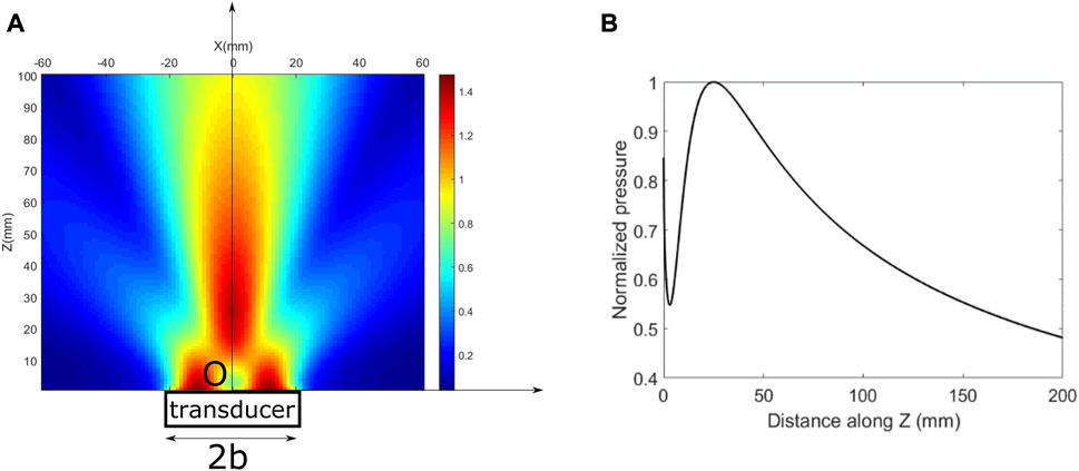
FIGURE 1. Normalized pressure distribution (A) full field (B) along Z at x = 0. Calculations have been performed using Matlab software.
Using a metasurface means controlling the phase delay in a specific plane along the direction of propagation. To simulate the presence of a lens, we therefore calculated the phase delay φ according to Eq. 2, originally proposed in 2014 by Li et al. (Li et al., 2014):
where
in which
We therefore use the quantization proposed (Memoli et al., 2017). Here, the phase space
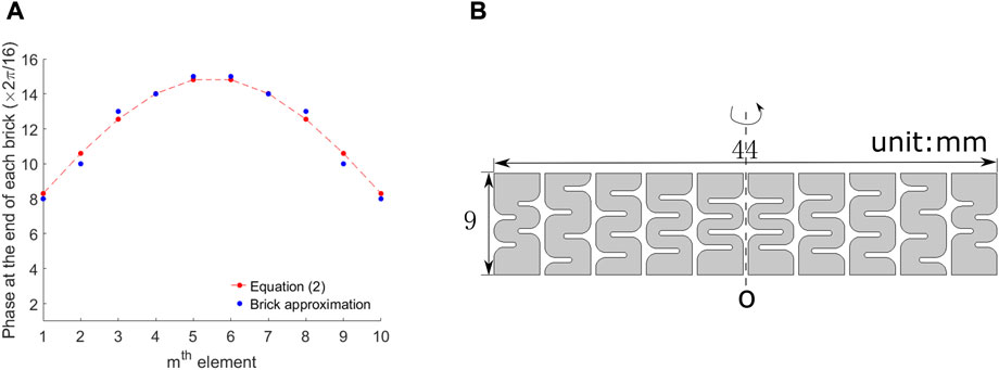
FIGURE 2. (A) Calculated and approximated phase distribution (B) Cross-section of the labyrinthine lens.
It is worth noting that, the longitudinal wave is mainly considered in this work and since the desired focal length is smaller than one wavelength (i.e., since we designed a “super-lens”), Eq. 3 may be expected to overestimate the actual focal length (Memoli et al., 2019). To evaluate this error, the behavior of the actual lens was simulated using a finite element method with the Acoustic Module in COMSOL Multiphysics 5.3. The whole inspection system is composed of different polymers with small impedance mismatch to minimize interface reflections and mode conversions. Figure 2 shows a typical result of these simulations for the case where a plane wave from the couplant layer impinges on a lens with different 3D printing materials (PLA, ABS, PMMA and UTR9000), resting on an infinite polymer sample by having perfectly matched layers at the boundary of the domain. The material properties are listed in Table 1. The mechanical and acoustic properties are slightly different between 3D printing and traditional processing (Ferreira et al., 2017).
Due to the impedance mismatch among the layers, the focal length has been slightly modified in Figure 3. All the materials focus at around 17 mm when Vsample = 2200 m/s. Both PLA and ABS give a smaller focal length if Vsample changes from 2200 m/s to 2600 m/s. By trading off between focal length sensitivity, cost, processability, and surface finish, UTR9000 was chosen for this study. Its pressure distributions are shown in Figure 4, with a good lateral focusing ability.
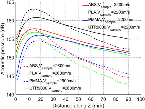
FIGURE 3. Simulated pressure with the selected bricks along Z at X = 0 for different manufacturing materials.
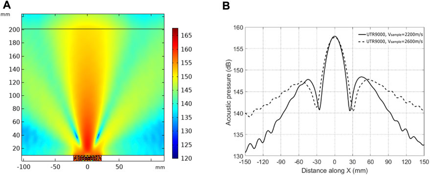
FIGURE 4. (A) simulated full field pressure with the selected bricks (lens made of UTR9000, Vsample = 2200 m/s) (B) simulated pressure at X = 50 mm from the metasurface (with side lobes 10 dB lower). Calculations here made using COMSOL Multiphysics 5.3.
Time domain simulation
After the lens design, time domain simulations were carried out using the k-space pseudo-spectral method (Treeby and Cox, 2010; Treeby et al., 2018) in MATLAB to mimic a hole defect inspection process in an acrylic sample (Vsample = 2600 m/s) delimited by perfectly matched layer (PML) boundaries. These simulations were later used to understand the wave-MSL-defect interaction during the experiments, where the through-transmission measurement scheme was adopted, due to the high attenuation in polymer materials. A hole defect of ϕ = 20 mm in diameter was centered at the theoretical focal length of 17 mm (see previous section), in an infinite domain (Figure 5A). The presence of the hole acted a secondary excitation source, and this generated multiple acoustic wave paths. To simplify further analysis, four wave paths were mainly considered: purely in the host material (Path I) and with single/three/five passes inside the hole (Path II, III, IV). This can also be visualized during simulations (Figure 5B), and four corresponding peaks can be found in Figure 5C. The signal to noise ratio in the MSL case becomes lower due to the scattering inside the MSL and the introduction of an additional interface.
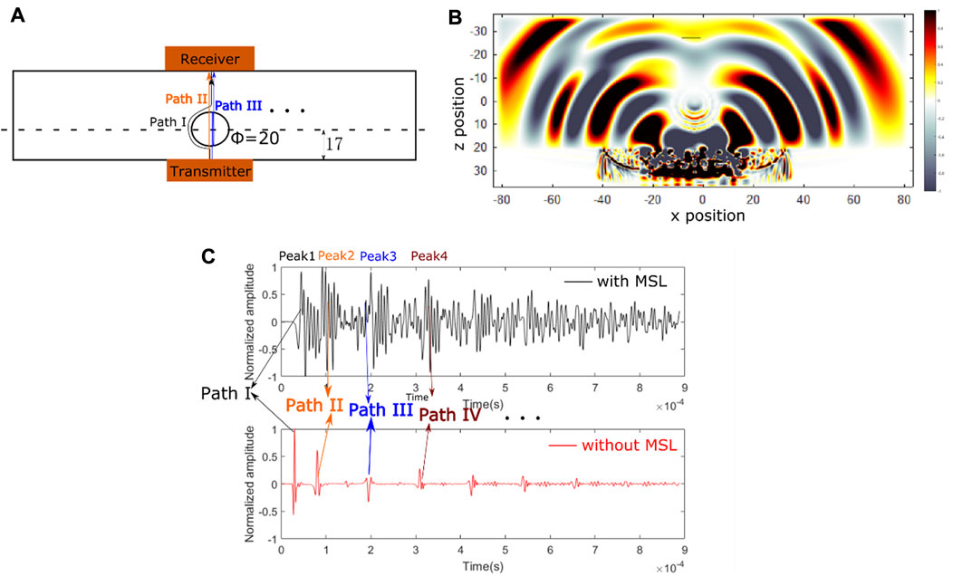
FIGURE 5. (A) Defect inspection scheme and wave paths (B) Snapshot of wave-defect interaction with MSL (C) Waveforms with and without MSL.
The defect diameter Dij can be further evaluated (Miyamoto et al., 2016) through peak i-j in Eq. 4:
in which V1 = 343 m/s and V2 = 2600 m/s are the ultrasound velocities in air and in the base material, respectively. Thanks to the focusing behavior, the peak amplitude of Peak 3 and Peak 4 is 80% of Peak 2 with MSL. This ratio is only 30% without MSL, so these two peaks risk being submerged by measurement noises during experiments. Assuming that all the peaks are visible, the calculation results are shown in Table 2. Both simulations gave satisfactory results, with the accuracy decreasing from
Experimental
Set-up
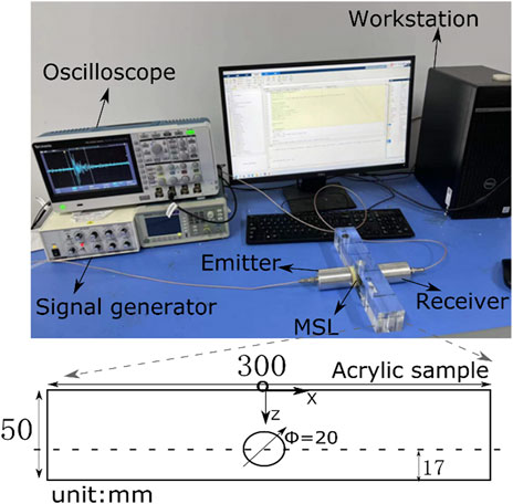
According to the previous simulation, two acrylic samples of 300 mm × 50 mm × 50 mm in dimension were tested. One has no defect and the other has the same hole defect as in the simulation. A pulsed source was excited from an ultrasonic pulser/receiver (DPR300, JSR Ultrasonics) to a commercial longitudinal wave transducer at 100 kHz coupled with MSL. The generated waveform was then received by another transducer of the same type and exported to an oscilloscope (TBS2204B, Tektronix). The waveform was recorded through the connection between MATLAB and the oscilloscope. The whole experimental setup is shown in Figure 6.
Lens printing
Both fused deposition modeling (FDM) and stereo lithography appearance (SLA) technologies have been tried for lens fabrication. The lens rings were printed separately to prevent excess shrinkage in Figure 7A. The printing direction is along the wave propagation to minimize the attenuation (Balvantín et al., 2020). The surface finish from SLA with UTR9000 (Figure 7C) is much better than that from FDM with PLA (Figure 7B), which impacts the wave propagation behavior. Adhesive tapes were added to the ring surfaces (Figure 7D) to prevent penetration of the couplant between the rings and to prevent interspace moving.
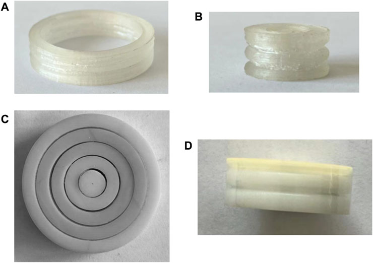
FIGURE 7. (A) Deformed MSL by printing as a whole from FDM with PLA (B) Coarse surface from FDM with PLA (C) Fine surface from SLA with UTR9000 (D) Fine surface protected by adhesive tapes during testing.
Energy profile comparison
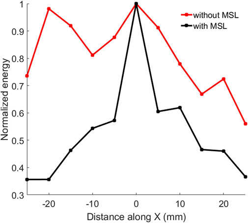
The focusing behavior was first evaluated in the intact sample. This was done by manually shifting the receiving probe along the direction of the sample in 5 mm steps and recording the transmitted energy. Due to the attenuation from the 3D printed polymer lens, the signal energy without MSL is nearly 26 times higher than that with MSL at a given position during measurement. However, the energy profile is much narrower with the lens compared to without the lens after normalization as shown in Figure 8. In particular, the profile width at −3 dB with the MSL is half of that without the lens at 50 mm from the surface with the source transducer. However, while the width of the beam with only the transducer does not change much in the 50 mm after the surface (see Figure 1A), the beam with the lens becomes three times wider moving from 17 mm to 50 mm (Figure 4A): the difference in width will be at least six times at 17 mm from the surface (i.e. at the focal length).
Defect inspection
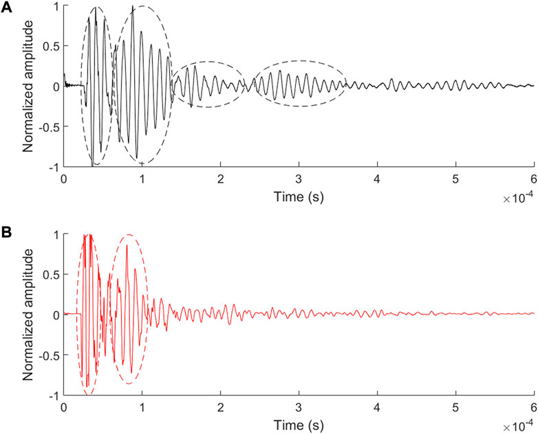
The SNR was found to be lower in experiments than in simulations. The presence of the defect can only be evaluated between Peak 1 and 2 without MSL (Figure 9), since Peak 3 and 4 cannot be recognized. In contrast, all the peaks can be observed with MSL thanks to the focusing behavior. The peak values and calculated diameters are shown in Table 3. The calculated diameters are 20.1 mm and 19.5 mm according to Peak 1 and 2 in both cases. The values for Peak 3 and 4 are 18.1 mm and 16 mm with MSL, respectively. Due to the wave reflection, scattering and mode conversion (Miyamoto et al., 2016), part of the normal incident longitudinal wave energy is transferred to shear wave energy. The wave packet extends continually and both mode waves become diffusive eventually after multiple scattering (Ahn et al., 2019).
Thus, although the diameter can also be determined from the later part of the wave, the error increases. Nevertheless, the availability of multiple values (in the MSL case) allows to reduce the statistical uncertainty. Information including both the interfaces and defect is different between these wave packets and requires a further study with more advanced signal processing.
Conclusion
This paper represents a systematic study of defect inspection using an acoustic MSL. Combining frequency/time domain analysis and additive manufacturing technology, an MSL can turn a traditional transducer into a focusing transducer at low cost. The ring scheme separates the incident plane wave into 10 channels and enables a free beam control design (e.g., convergence, divergence) as industrial LEGO bricks. It functions as a traditional delay line to prevent near field effect and controls the phase delay profile to converge the ultrasonic beam near the surface. More transmission information was observed with MSL during defect inspection, which will facilitate defect analysis, especially when the early arrival is blurred by electronic noises.
Lots of metasurface lens from airborne sound may shed light on the wave manipulation in solid materials. Through-transmission measurement scheme was chosen to show here the focusing behavior where the longitudinal wave dominates. However, simultaneous multi-mode control (Yuan et al., 2020) combining interfaces (Manjunath and Rajagopal, 2019) created by MSL need to be further investigated. The additional attenuation brought by the MSL required a more compact lens design and proper material selection as well. Pulse-echo measurement is widely applied in NDT/SHM due to a single-sided accessibility. Future studies will explore how a MSL can be beneficial even in such a context, where the reflection wavefront is no longer a plane wave containing different modes and its interaction with MSL becomes complex. Advanced signal processing techniques will be required to extract defect information from MSL modulated reflection signals, thus enabling practical applications. With the rapid advancement of additive manufacturing, such a scheme opens an economic option with a single fixed transducer for full-field imaging compared to an expensive phased array system.
Data availability statement
All of the data are included in the published article, further inquiries can be directed to the corresponding authors.
Author contributions
QZ: Conceptualization, methodology, writing – original draft, formal analysis, funding acquisition. YZ: Software, investigation, data curation. HZ: Validation, resources, writing – review and editing. GM: Methodology, supervision, writing – review and editing, funding acquisition.
Funding
This work was supported by the National Natural Science Foundation of China (Grant Nos. 11904223, 12011530422, 12174245) and by the UKRI Fellowship “AURORA” (EP/ S001832/1) in UK. Collaboration between the teams has been initiated by The Royal Society International Exchanges program (project IES\R1\201309), even if travel was no longer possible.
Conflict of interest
The authors declare that the research was conducted in the absence of any commercial or financial relationships that could be construed as a potential conflict of interest.
Publisher’s note
All claims expressed in this article are solely those of the authors and do not necessarily represent those of their affiliated organizations, or those of the publisher, the editors and the reviewers. Any product that may be evaluated in this article, or claim that may be made by its manufacturer, is not guaranteed or endorsed by the publisher.
References
Ahn, E., Shin, M., Popovics, J. S., and Weaver, R. L. (2019). Effectiveness of diffuse ultrasound for evaluation of micro-cracking damage in concrete. Cem. Concr. Res. 124, 105862. doi:10.1016/j.cemconres.2019.105862
Al-Tameemi, H. A., Long, H., and Dwyer-Joyce, R. S. (2018). Initiation of sub-surface micro-cracks and white etching areas from debonding at non-metallic inclusions in wind turbine gearbox bearing. Wear 407, 22–32. doi:10.1016/j.wear.2018.03.008
Askari, M., Hutchins, D. A., Thomas, P. J., Astolfi, L., Watson, R. L., Abdi, M., et al. (2020). Additive manufacturing of metamaterials: A review. Addit. Manuf. 36, 101562. doi:10.1016/j.addma.2020.101562
Balvantín, A. J., Rojas-mancera, E., Ramirez, V. A., Diosdado-de-la-peña, J. Á., Limon-leyva, P. A., and Figueroa-díaz, R. A. (2020). The suitability of using 3D PLA printed wedges for ultrasonic wave propagation. IEEE Access 8, 15205–15209. doi:10.1109/ACCESS.2020.2967211
Bindal, V. N. (2000). Water-based couplants for general purpose use for ultrasonic NDT applications. J. Sci. Ind. Res. (India). 59, 935–939.
Chen, A., Wang, Y., Wang, Y., Zhou, H. T., and Yuan, S. M. (2022). Design of acoustic /elastic phase gradient metasurfaces : Principles , functional elements , tunability , and coding. Appl. Mech. Rev. 74, 1–36. doi:10.1115/1.4054629
Chen, S., Fan, Y., Yang, F., Jin, Y., Fu, Q., Zheng, J., et al. (2019). Engineering coiling-up space metasurfaces for broadband low-frequency acoustic absorption. Phys. Status Solidi RRL. 13, 1900426–6. doi:10.1002/pssr.201900426
Chen, S., Fan, Y., Yang, F., Sun, K., Fu, Q., Zheng, J., et al. (2021). Coiling-up space metasurface for high-ef fi cient and wide-angle Acoustic wavefront steering. Front. Mat. 8, 1–8. doi:10.3389/fmats.2021.790987
Clough, A. R., and Edwards, R. S. (2015). Characterisation of hidden defects using the near-field ultrasonic enhancement of Lamb waves. Ultrasonics 59, 64–71. doi:10.1016/j.ultras.2015.01.012
Ferreira, R. T. L., Amatte, I. C., Dutra, T. A., and Bürger, D. (2017). Experimental characterization and micrography of 3D printed PLA and PLA reinforced with short carbon fibers. Compos. Part B Eng. 124, 88–100. doi:10.1016/j.compositesb.2017.05.013
Gliozzi, A. S., Miniaci, M., Bosia, F., Pugno, N. M., and Scalerandi, M. (2015). Metamaterials-based sensor to detect and locate nonlinear elastic sources. Appl. Phys. Lett. 107, 161902–161947. doi:10.1063/1.4934493
Jawahir, I. S., Brinksmeier, E., M’Saoubi, R., Aspinwall, D. K., Outeiro, J. C., Meyer, D., et al. (2011). Surface integrity in material removal processes: Recent advances. CIRP Ann. 60, 603–626. doi:10.1016/j.cirp.2011.05.002
Joubert, P., Vourc, E., Tassin, A., and Diraison, Y. L (2010). Source separation techniques applied to the detection of subsurface defects in the eddy current NDT of aeronautical lap-joints. NDT E Int. 43, 606–614. doi:10.1016/j.ndteint.2010.06.005
Kalore, S. A., Sivakumar Babu, G. L., and Mallick, R. B. (2019). Design approach for drainage layer in pavement subsurface drainage system considering unsaturated characteristics. Transp. Geotech. 18, 57–71. doi:10.1016/j.trgeo.2018.11.004
Koester, L. W., Zuhlke, C., Alexander, D., Fuller, A. J., Wilson, B. M., and Turner, J. A. (2012). Near-race ultrasonic detection of subsurface defects in bearing rings. Bear. Steel Technol. 9th Vol. Adv. Roll. Contact Fatigue Strength Test. Relat. Substit. Technol., 84–101. doi:10.1520/stp104623
Li, Y., and Assouar, M., (2016). Acoustic metasurface-based perfect absorber with deep subwavelength thickness. Appl. Phys. Lett. 108, 063502. doi:10.1063/1.4941338
Li, Y., Jiang, X., Li, R. Q., Liang, B., Zou, X. Y., Yin, L. L., et al. (2014). Experimental realization of full control of reflected waves with subwavelength acoustic metasurfaces. Phys. Rev. Appl. 2, 064002–064011. doi:10.1103/PhysRevApplied.2.064002
Li, Z., Yang, D. Q., Liu, S. L., Yu, S. Y., Lu, M. H., Zhu, J., et al. (2017). Broadband gradient impedance matching using an acoustic metamaterial for ultrasonic transducers. Sci. Rep. 7, 42863–42869. doi:10.1038/srep42863
Liu, J. Y., Gong, J. L., Qin, L., Guo, B., and Wang, Y. (2015). Three-Dimensional visualization of subsurface defect using lock-in thermography. Int. J. Thermophys. 36, 1226–1235. doi:10.1007/s10765-014-1717-y
Manjunath, C. T., and Rajagopal, P. (2019). Lensing in the ultrasonic domain using negative refraction induced by material contrast. Sci. Rep. 9, 6368–8. doi:10.1038/s41598-019-42655-3
Melnikov, A., Maeder, M., Friedrich, N., Pozhanka, Y., Wollmann, A., Scheffler, M., et al. (2020). Acoustic metamaterial capsule for reduction of stage machinery noise. J. Acoust. Soc. Am. 147, 1491–1503. doi:10.1121/10.0000857
Memoli, G., Caleap, M., Asakawa, M., Sahoo, D. R., Drinkwater, B. W., and Subramanian, S. (2017). Metamaterial bricks and quantization of meta-surfaces. Nat. Commun. 8, 14608. doi:10.1038/ncomms14608
Memoli, G., Chisari, L., Eccles, J. P., Caleap, M., Drinkwater, B. W., and Subramanian, S. (2019). Vari-sound: A varifocal lens for sound. Conf. Hum. Factors Comput. Syst. - Proc., 1–14. doi:10.1145/3290605.3300713
Miyamoto, R., Mizutani, K., Ebihara, T., and Wakatsuki, N. (2016). Effect of mode conversion on defect detection and size estimation in billet from time-of-flight profile by ultrasonic transmission method. Jpn. J. Appl. Phys. 55, 07KC06. doi:10.7567/JJAP.55.07KC06
Potter, J. N., Wilcox, P. D., and Croxford, A. J. (2018). Diffuse field full matrix capture for near surface ultrasonic imaging. Ultrasonics 82, 44–48. doi:10.1016/j.ultras.2017.07.009
Resch, M. T., Nelson, D. V., Yuce, H. H., and Ramusat, G. F. (1985). A surface acoustic wave technique for monitoring the growth behavior of small surface fatigue cracks. J. Nondestruct. Eval. 5, 1–7. doi:10.1007/BF00568757
Schmerr, L. W. (2015). in Fundamentals of ultrasonic phased arrays. Editors J. R. Barber, A. Arbor, and A. Klarbring (Cham: Springer International Publishing). doi:10.1007/978-3-319-07272-2
Thippeswamy, M., Kuchibhatla, S. A. R., and Rajagopal, P. (2021). Concentric shell gradient index metamaterials for focusing ultrasound in bulk media. Ultrasonics 114, 106424. doi:10.1016/j.ultras.2021.106424
Tian, Y., and Shen, Y. (2020). Selective guided wave mode transmission enabled by elastic metamaterials. J. Sound. Vib. 485, 115566. doi:10.1016/j.jsv.2020.115566
Tol, S., Degertekin, F. L., and Erturk, A. (2019). 3D-printed phononic crystal lens for elastic wave focusing and energy harvesting. Addit. Manuf. 29, 100780. doi:10.1016/j.addma.2019.100780
Treeby, B. E., and Cox, B. T. (2010). k-Wave : MATLAB toolbox for the simulation and reconstruction of photoacoustic wave fields. J. Biomed. Opt. 15, 021314. doi:10.1117/1.3360308
Treeby, B., Lucka, F., Martin, E., and Cox, B. T. (2018). Equivalent-source acoustic holography for projecting measured ultrasound fields through complex media. IEEE Trans. Ultrason. Ferroelectr. Freq. Control 65, 1857–1864. doi:10.1109/TUFFC.2018.2861895
Turner, J. A., Wilson, B., Tarawneh, C., and Fuller, A. J. (2015). “Multiple frequency ultrasonic detection of subsurface near-race inclusions for improved fatigue life performance.” in Joint Rail Conference, San Jose, USA, March 2015, 5785. doi:10.1115/JRC2015-5785
Xie, Y., Fu, Y., Jia, Z., Li, J., Shen, C., Xu, Y., et al. (2018). Acoustic imaging with metamaterial luneburg lenses. Sci. Rep. 8, 16188. doi:10.1038/s41598-018-34581-7
Yuan, S., Chen, A., Cao, L., Zhang, H., Fan, S., Assouar, B., et al. (2020). Tunable multifunctional fish-bone elastic metasurface for the wavefront manipulation of the transmitted in-plane waves. J. Appl. Phys. 128, 224502. doi:10.1063/5.0029045
Zenia, S., Ben Ayed, L., Nouari, M., and Delamézière, A. (2015). An elastoplastic constitutive damage model to simulate the chip formation process and workpiece subsurface defects when machining CFRP composites. Procedia CIRP 31, 100–105. doi:10.1016/j.procir.2015.03.100
Keywords: metasurface, additive manucatruing, ultrasonic, near surface, NDT
Citation: Zhu Q, Zhang Y, Zhang H and Memoli G (2022) Ultrasonic inspection of near surface defects with additive manufactured metasurface lens. Front. Mater. 9:1025518. doi: 10.3389/fmats.2022.1025518
Received: 23 August 2022; Accepted: 04 October 2022;
Published: 19 October 2022.
Edited by:
Yadong Xu, Soochow University, ChinaReviewed by:
Chen Shen, Rowan University, United StatesYue-Sheng Wang, Tianjin University, China
Yuancheng Fan, Northwestern Polytechnical University, China
Chao Tian, University of Science and Technology of China, China
Copyright © 2022 Zhu, Zhang, Zhang and Memoli. This is an open-access article distributed under the terms of the Creative Commons Attribution License (CC BY). The use, distribution or reproduction in other forums is permitted, provided the original author(s) and the copyright owner(s) are credited and that the original publication in this journal is cited, in accordance with accepted academic practice. No use, distribution or reproduction is permitted which does not comply with these terms.
*Correspondence: Qi Zhu, UV9aSFVAc2h1LmVkdS5jbg==; Gianluca Memoli, Ry5NZW1vbGlAc3Vzc2V4LmFjLnVr
 Qi Zhu
 Yuanjun Zhang1
 Gianluca Memoli

