 Huaxia Deng
 Xinyu Lian2†
 Xinglong Gong
- 1CAS Key Laboratory of Mechanical Behavior and Design of Materials, Department of Modern Mechanics, University of Science and Technology of China, Hefei, China
- 2School of Instrument Science and Opto-electronics Engineering, Hefei University of Technology, Hefei, China
With the development of magnetorheological fluid (MRF) technology, variable stiffness and damping MRF dampers as semi-active controllers gradually show their unique advantages in the vibration control field. This paper reviews recent journal articles on the principles, characteristics, structure design, modelling and applications of variable stiffness and damping MRF dampers. The principle includes the force behaviour of the MRF fluid and the mechanism of the variable stiffness and damping MRF damper. Characteristics introduce the damper’s force-displacement relationships, which have frequency dependence and amplitude dependence. Following this, typical dampers structures are discussed, including electromagnetic design and coil configuration. After that, some common models and parameter optimization methods are presented. Furthermore, taking vehicle suspension as an example, the applications of variable stiffness and damping MRF dampers in some fields are proposed in this paper.
1 Introduction
Magnetorheological fluid (MRF) is an intelligent material which can change the internal structure quickly and reversibly under the action of the magnetic field, thus changing some mechanical properties (Parlak et al., 2012, 2013). Due to the excellent relationship between the mechanical system and electronic control, the damping of MRF devices can be adjusted according to the external vibration environment, which is widely used in semi-active vibration control (Guo et al., 2015; Ruan et al., 2020). The MRF Dampers have the advantages of good reversibility, fast response speed and simple control parameters (Rabinow, 1948; Genc, 2022) and can be widely used in vehicle suspension systems, landing gear systems, and ship and building isolator systems (Marathe et al., 1998; Yao et al., 2002; Kim et al., 2009). Another magnetorheological (MR) device, MR elastomers, has been studied because their moduli can be affected by external magnetic fields and have been proven to have variable stiffness properties (Deng and Gong, 2007; Li et al., 2010; Liao et al., 2012; Li et al., 2013; Yang et al., 2016; Wang et al., 2020). Du H. et al. proposed the design of an automobile seat suspension system by using the variable stiffness characteristics of MR elastomers (Du et al., 2011), Eem S.H. et al. proposed the MR elastomer vibration isolation system (Eem et al., 2013). However, MR elastomers can only change the stiffness and have a minor stroke (Guan et al., 2008; Wang et al., 2017; Jiang et al., 2020; Jin et al., 2020; Yu et al., 2021).
Using an MRF damper as a simplex variable damping or stiffness element limits its ability to control vibration to a certain extent. On this basis, an MRF damper with variable stiffness and damping characteristics is proposed, which has the advantages of both MR Fluid and MR Elastomer (Liu et al., 2008; Dong, 2013). Spelta. Xu. Y.H. et al. proposed the conceptual model of a variable stiffness and damping structure (Xu and Ahmadian, 2013; Xu et al., 2014). Liu Y.Q. et al. proposed a mechanism with variable stiffness and damping composed of two MR dampers and linear springs and verified that the system could achieve variable stiffness and damping through experiments (Liu et al., 2006). On this basis, to independently control the variable stiffness and damping performance of the system, Liu Y.Q. et al. further studied a new variable damping and variable stiffness system. Li W.H. designed a vibration isolation device consisting of an air spring, MR valve and accumulator (Zhang et al., 2009), and verified the advantages of variable stiffness and damping in building vibration isolation through simulation and experiments. Sun S.S. et al. applied the damper to high-speed train suspension and improved the dynamic stability of the train (Sun et al., 2014). As people began to dig deeper, variable stiffness and damping MR dampers showed high efficiency in vibration control (Zhu et al., 2020). Compared with the traditional MR damper, the variable stiffness and damping damper have more complex nonlinear characteristics, and an accurate and simple model is needed in the application (Song et al., 2003; Ahn et al., 2005; Opie and Yim, 2009). In addition to the Bingham model and Bouc-wen model, the piecewise function model is used to describe the variable stiffness characteristics (Xu et al., 2014; Huang et al., 2019; Sun et al., 2019). An adaptive model parameter identification method is also necessary (Lian et al., 2021). In the control strategy, simple sky-hook control is still the most widely used (Morales et al., 2018). Fuzzy control, sliding mode control and so on also have a good effect (Sun et al., 2017; Yao et al., 2017; Tang et al., 2020). However, a more suitable control scheme is needed for variable stiffness and damping MR dampers (Çeşmeci and Engin, 2010; Parlak and Engin, 2012; Wasiwitono et al., 2016; Şahin et al., 2021).
Variable stiffness and damping MRF dampers have made some achievements in recent years, improving the efficiency of vibration reduction and proposing a new solution for semiactive vibration control. However, it is still necessary to put forward a perfect control method and explore the advantages of these dampers in practical applications. This paper introduces the working mechanism and unique mechanical characteristic curve of variable stiffness and damping MRF dampers. Then, the research progress of variable stiffness and damping MR dampers in structural design, modelling and practical application is reviewed. Finally, the working prospects of these dampers are summarized and discussed.
2 Principle
Magnetorheological fluids are suspensions of micron-sized, magnetisable particles in an appropriate carrier liquid, whose yield stress increases considerably in the presence of an externally applied magnetic field, which can be used to develop dampers. Figure 1 shows the relationship between shear stress and shear strain under the varying magnetic field. As the magnetic field increases, the shear stress under the same shear strain increases accordingly. When the shear strain is zero, the shear stress is also zero. The behaviour of the MR fluid is divided into pre-yield and post-yield regions, depending on whether the fluid is stressed below or above a critical yield stress value. The yield point γy indicates the different yield stress of MR Fluid under various magnetic fields. When the stress is less than the yield stress, the MRF deforms under the action of external force, and the relationship between stress and strain is approximately proportional. When the stress exceeds yield stress, the MR Fluid behaves like a fluid.
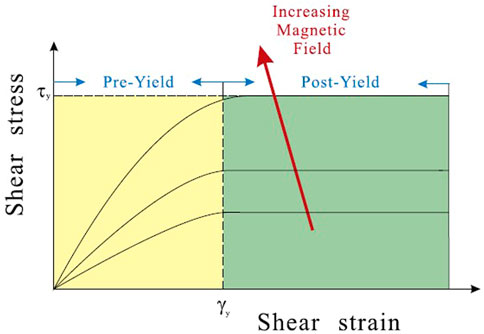
FIGURE 1. Force behaviour of MR fluid (Deng et al., 2017).
The MRF dampers developed based on the MRF properties have the same nonlinear operating characteristics. An external magnetic field controls the damping capabilities. Based on this characteristic, the variable stiffness and damping MRF damper is proposed. It can be divided into two kinds: the series type and the parallel type. The series variable stiffness and damping MRF damper consists of two modules in series. Each module contains an MRF damper and a spring with constant stiffness. The equations of motion of the semi-active vibration control system are as follows:
While the equation of the equivalent model is:
The equivalent mass and equivalent damping can be derived from the force equation as follows:
The c1 and c2 represent the damping of each damper. k1 and k2 represent the stiffness of the springs. x0 is the input displacement, xm is the middle point of the two modules, and x is the displacement of the output. The equivalent stiffness and damping of the whole system can be changed by changing c1 and c2. However, it is difficult to control the damping and stiffness separately by this way. Based on this model, the parallel variable stiffness and damping MRF damper is proposed, as shown in Figure 2. This parallel variable stiffness and damping MRF damper also includes two damping elements and two stiffness elements. The specific structure is a damping element and a parallel structure of a stiffness element in series with another stiffness element, and then the whole and another damping element in parallel. The working process can be divided into three modes. When c2 is small enough, the damping force f2 will allow the relative motion between the two damping modules. In this case, the spring k1 and spring k2 work in series because both springs deform. With the increase in damping force f2, the contribution of spring k1 to the overall stiffness of the system continues to change. Due to the small deformation of spring k1, the effective stiffness of the whole system is still small. On the other hand, when the damping force f2 is large enough to prevent the relative motion between the two damping modules, it is working in connection mode because only spring k2 will have a deformation in response to the external force. Therefore, the stiffness of the whole system is between the stiffness of two springs in series and the stiffness of spring k2, and the damping c2 is the key to changing the system’s stiffness. At the same time, the damping variability is realized by adjusting the damping c1.
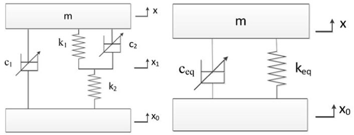
FIGURE 2. The model of the parallel variable stiffness and damping MRF damper (A) The original model (B) The equivalent model.
According to the force analysis of the actual structure in Figure 3, F1, F2, F3 are the forces transferred to the inner cylinder, outer cylinder and the ectotheca of the outer chamber, which are expressed as:
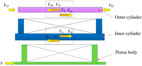
FIGURE 3. Force transmission for the MRF dampers.
The physical model of the parallel variable stiffness and damping MRF damper is established and can explain this three working stages through the actual motion process.
Stage 1: The inner cylinder and the outer cylinder are stationary.
At the beginning of the work of the MRF damper, the external force is directly applied to the upper connector connected with the piston rod in the damper. Due to the static friction force between the piston rod and the inner cylinder, only when the applied force exceeds the minimum shear stress will it begin to flow and produce shear deformation. Therefore, if the force does not reach the sum of the maximum static friction force and the yield force of the MR fluid in the inner cylinder, the MR fluid will not produce shear flow, and the relative displacement between the piston rod and the inner cylinder is zero. As the external force on the damper increases until the inner cylinder piston overcomes the sum of the friction force and the yield force of the MR fluid, the piston rod will begin to move relative to each other. This is also the turning point from the first stage to the second stage. The external force in this stage is calculated as:
Stage 2: The inner cylinder moves while the outer cylinder is stationary.
As the force of MR fluid in the first stage exceeds the force value indicated in the above formula, the piston rod and the inner cylinder are relative slidings, static friction also turns into sliding friction. The MR fluid in the inner cylinder generates shear stress. At the same time, the external force is transmitted to spring 2 through the connection of the damper, and spring 2 is compressed to produce elastic force proportional to the amount of compression and transferred to the external cylinder of the damper connected with it. In this stage, the force transferred to the outer cylinder of the damper does not reach the sum of the minimum shear stress of the MR fluid in the outer cylinder and the static friction force between the inner and outer cylinder, so the outer cylinder remains static and the MR fluid in it does not flow. The turning point of the second stage into the third stage is that the external cylinder of the damper remains stationary but has a trend of relative motion. The force includes the inner chamber damping force and the elastic force of spring 2.
At this time, the velocity of the piston of the external cylinder is infinitesimally small and approaches zero. The critical condition is described as:
The turning point x∗ is:
Stage 3: The inner cylinder and the outer cylinder move simultaneously.
The spring 2 is continuously compressed by the action of external force, and the elastic force proportional to the amount of deformation is increasing, so the force transmitted to the outer cylinder is also increasing. Once the force exceeds the minimum yield stress of MR fluid, the MR fluid in the outer cylinder yields and begins to flow. The outer wall of the inner cylinder can be seen as the piston rod of the outer cylinder, and the relative movement between the outer cylinder is generated. At this time, the inner cylinder and the outer cylinder are moving, and the spring 1 also produces elastic deformation, which produces the corresponding elastic force after compression. The analysis shows that the force transmitted by the spring 2 is equal to the sum of the damping force produced by the outer cylinder and the elastic force produced by the spring 1. At the same time, the force of the spring 2 is equal to the sum of the damping force produced by the inner cylinder of the damper, and the spring 1 has the same displacement as the piston of the outer cylinder. The force of the MRF device are given through the following equations:
Through the mechanics analysis, when x∗ < x, the equivalent stiffness is given as:
When x∗⩾x, keq ≈ k2.
The parallel MRF damper further subdivides the working process and realizes the independent control of variable stiffness and variable damping, which make the MRF damper more widely used.
3 Characteristics
The traditional MRF dampers have lots of characteristics. Dampers have hysteresis phenomenon, usually non-symmetrical hysteresis. The average slope of the hysteresis loop depends on the applied current and excitation conditions, including frequency and stroke. The force-velocity curve of MRF Damper has non-symmetrical hysteresis near zero velocity. There are two domains during the dampers operate: the pre-yield and post-yield regions and the yield force varies with the applied magnetic field. The MRF damper exhibits a passive behaviour when applied zero current. By observing the force-displacement curve of the damper, it is found that the displacement of the damper can reach the amplitude after several input cycles, and the damper has a stable response. The number of cycles depends on the frequency of the signal. Which proved that the MRF damper has frequency and displacement amplitude dependence.
In addition to the similar characteristics of the traditional dampers, variable stiffness and damping MRF dampers have more complex nonlinear links. Analysis and study of the characteristics are essential to developing and applying this damper. The damping force depends on the magnitude of the magnetic field current. When the corresponding coil current is changed, the damping force of the two damping modules can be adjusted to control the stiffness and damping of the damper, as shown in Figure 4. The equivalent stiffness of the damper is represented by the slope of the corresponding segments. Figure 4A shows that the equivalent stiffness of the device changes with increasing I2 when I1 = 0A. The inflexion point of the variable stiffness characteristic curve is marked by A-F. There are three stages named segments AB, BC and CD. In the AB stage, the applied force conquers the static friction and the initial damping force and there is no displacement for the device. In the BC stage, because of the damping force f2, the stiffness of the whole system is equal to k2. On the other hand, the damping force f2 increases with larger I2, which causes the length of segment BC to lengthen and the force at inflexion point C to be smaller. In stage CD, two springs are working in a series state. The slope of the AD segment represents the equivalent stiffness of the whole system. The changes in I2 affect the initial damping force of the outer chamber and have obvious effects on the equivalent stiffness of the MRF device. When the input current I2 exceeds a specific range, the maximum equivalent stiffness can only achieve the stiffness of spring 2. In addition, the equivalent stiffness is also affected by the structural parameters, such as the ratio between two springs, length of the piston, effective cross-sectional area of the piston and so on. Therefore, the damper should be designed according to different application scenarios to determine the equivalent stiffness range at work. After the MRF device structure is designed and assembled, the stiffness of the damper also can be changed by adjusting the control current applied to the outer chamber. Figure 4B shows that when I2 = 0A, increasing I1 leads to the variability of the equivalent damping of the MR device. The whole system works like the traditional MRF damper with only damping variable capability and the growth of the enclosed area means an increase in the damping force.
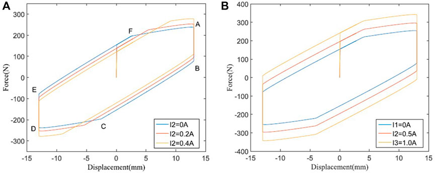
FIGURE 4. Force-displacement relationships of the variable stiffness and damping MR damper (A) Change the stiffness (B) Change the damping (Deng et al., 2017).
The effectiveness of changing the loading frequency of the traditional MRF damper and variable stiffness and damping MRF damper is shown in Figure 5. Similar to traditional MRF dampers, the peak force and equivalent damping increase when the loading frequency increases. Figure 6 shows the responses of the MRF damper when changing loading amplitudes with the same testing frequency and currents. The two kinds of dampers have the same property: the equivalent damping increases when the amplitude increases. At the same time, the variable stiffness and damping MRF damper retains the characteristic of variable stiffness. The variable stiffness and damping MRF damper also has the same characteristics as the traditional MRF damper. It presents a nonsymmetric hysteretic response, especially in the vicinity of turning points. The damper exhibits passive behaviour when zero current is applied. The dynamic characteristics of the damper can be controlled by changing the control current and has frequency dependence as well as displacement amplitude dependence.
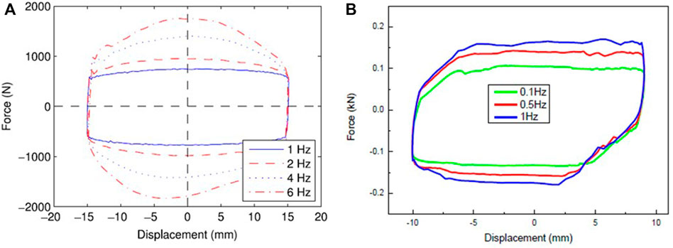
FIGURE 5. Force-displacement relationships when changing the frequency (A) Traditional MR damper (Wang and Liao, 2011) (B) variable stiffness and damping MR damper (Sun et al., 2015b).
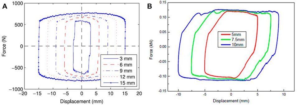
FIGURE 6. Force-displacement relationships when changing the amplitude (A) Traditional MR damper (Wang and Liao, 2011) (B) variable stiffness and damping MR damper (Sun et al., 2015b).
4 Structure design
MRFs have multiple operation modes based on three basic modes: flow modes (valve mode), direct shear mode, and squeeze mode. MRF dampers generally adopt the flow mode and direct shear mode. The MRF damper consists of a magnetic circuit and an MRF cylinder in either mode. The magnetic circuit needs to provide a controllable magnetic field as the control unit of the MRF Damper. The MRF cylinder serves as the output unit of mechanical movement. Completing the basic design at the same time also needs to consider the damper’s durability and sealing. Different structural designs are often proposed in different application scenarios.
In practical applications, the variable stiffness and damping MRF dampers structure need to be adjusted to adapt to more working environments. In addition, the mechanical properties of dampers are often related to the structural design. Several typical structural design schemes are proposed below, which are mainly divided into two kinds the single spring structure and the multi-spring structure. The type of single spring MRF damper composed of a spring, piston rod, double-piston, double electromagnetic coil and seal is shown in Figure 7. Each damping cylinder has a set of electromagnetic coils that provide power for the MR fluid filled in the reserve. The piston rod can move relative to the two cylinders, and the spring provides rigidity for this relative movement. I1 and I2 generate a magnetic field around the support structure to control the upper and lower resistance forces.
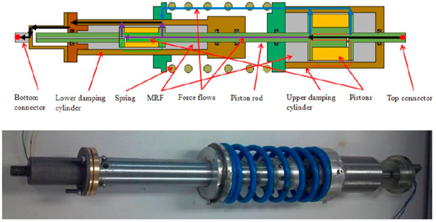
FIGURE 7. Damper with one spring (Sun et al., 2015b).
To adapt to more working scenarios, the variable stiffness MRF damper expands more structural forms through the design of damping modules and elastic modules. As shown in Figure 8A, the double parameter variable stiffness MRF damper is composed of upper and lower connectors, a piston rod, two springs and two damping chambers. The damping chamber is provided with a group of electromagnetic coils and a sealing piston. The piston rod passes through two coaxial damping chambers filled with MRF fluid, and the outer film of the inner damping chamber acts as the piston rod of the outer damping chamber. The spring provides upper and lower support forces for the outer damping chamber. The working environment of the variable stiffness damper is the mixed mode of the valve mode and direct shear mode. The magnetism generated by the inner cavity coil and the outer cavity coil is represented by green lines and red lines respectively. The inner cavity and the outer cavity are independent of each other, and the two damping forces are controlled by the external magnetic field. Another damper composed of two damping elements and two elastic elements is shown in Figure 8C. The overall structural design is similar to that of the above damper, but the stroke is shortened. This MRF damper can be applied to a vibration environment with a small vibration amplitude, reducing the structure size. Figures 8B,E shows the characteristic curve of the two kinds of dampers under current change. The stiffness and damping of the damper can be controlled by changing the current of the inner and outer cylinders separately. The nonlinear characteristics of dampers with different structures are also different and need to be selected according to the environment and requirements. There are many ways to improve the multi-spring damper structure. The structure shown in Figure 8D has the design of an extra accumulator. The solid line shows the magnetic circuit generated by the electromagnetic coil extending coaxially around the piston in the internal damping cylinder. According to the characteristics of the MR fluid, the external magnetic field is used to control the damping force of the inner cylinder. The effective working range and damping characteristics of the damper can be changed through this structural design, which expands the application scenarios of the damper.
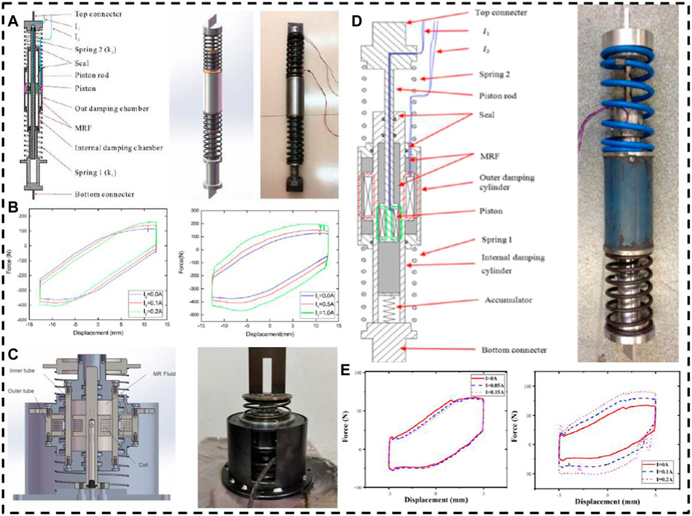
FIGURE 8. Variable stiffness and damping MRF damper with double spring (A) Damper with a larger motion (Deng et al., 2017) (B) characteristic of large motion damper (Deng et al., 2017) (C) Damper with a small motion (Lian et al., 2021) (D) Damper with multi-spring (Sun et al., 2015a) (E) characteristic of small motion damper (Lian et al., 2021).
5 Modeling
The MRF damper models can be divided into parametric models and non-parametric models, which are proposed to describe the dynamic behaviour of the damper. The parametric model is based on idealized physical components, including the Bingham model, the Bouc–Wen model and so on. Most of the parameters of these models have practical physical meanings. The non-parametric model uses analytical expressions to describe the characteristics of the modelled equipment on the basis of analyzing the test data (Wang and Liao, 2011). It can avoid some defects of parametric modelling and has robustness. It includes the polynomial model, the neural network model, the fuzzy model and so on. These models are explained in detail in the citation (Şahin et al., 2010).
The variable stiffness and damping MRF damper have complex nonlinearity, a high-precision model is essential for the semiactive control effect. Up to now, the Bingham model and the Bouc-Wen model are widely used in the application of dampers. The Bingham model combines a coulomb friction element and a viscous dashpot. The force F(t) is as follows:
Where
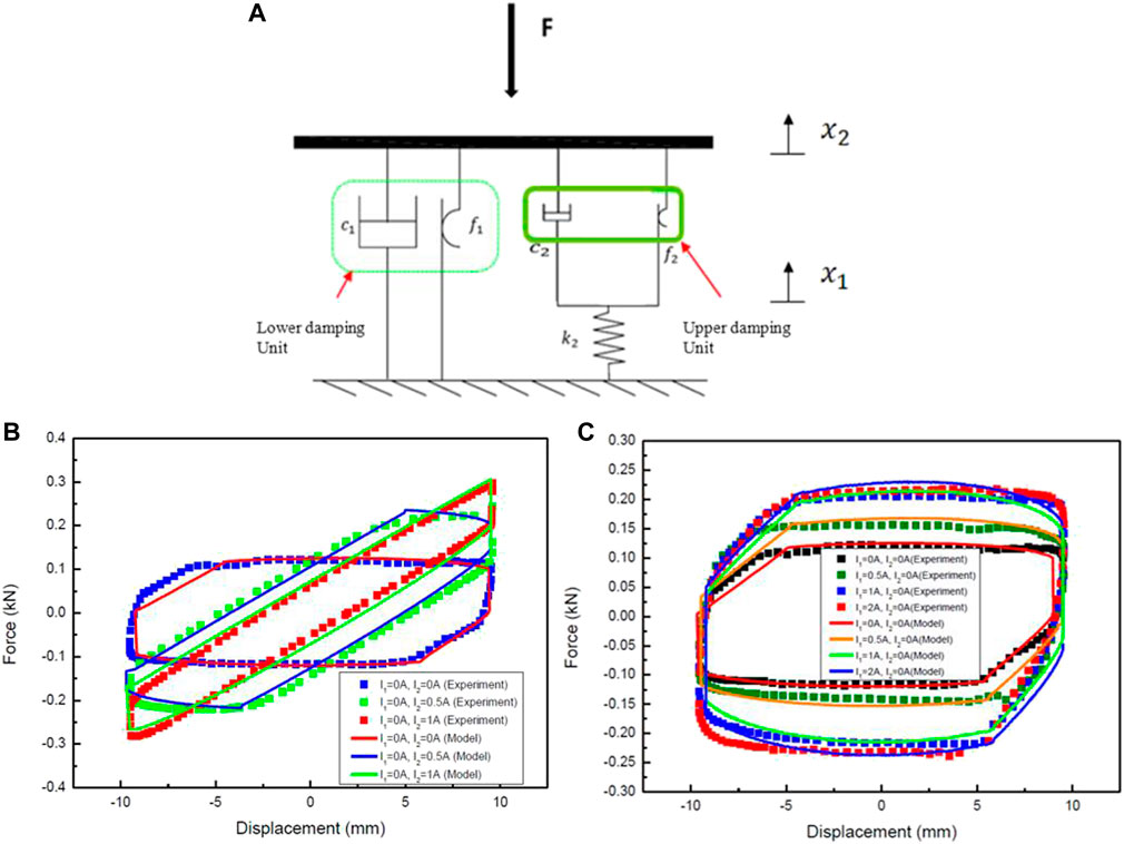
FIGURE 9. The model with Bingham components (A) The schematic diagram (B) Comparison of experimental and simulation results under variable stiffness (C) Comparison of experimental and simulation results under variable damping (Sun et al., 2015b).
When
When
As shown in Figure 9B, C, the proposed model reasonably simulates the variable stiffness characteristics and the variable damping characteristics of the damper. However, the Bingham model has few parameters, which leads to the low accuracy of the description of the damper loop curve to some extent.
The Bouc-Wen model uses more parameters than the Bingham model and is also widely used. Figure 10A is a schematic diagram of the phenomenological model with two Bouc-Wen components and the parameters were fitted by the least-square method. The mathematical model is as follows:
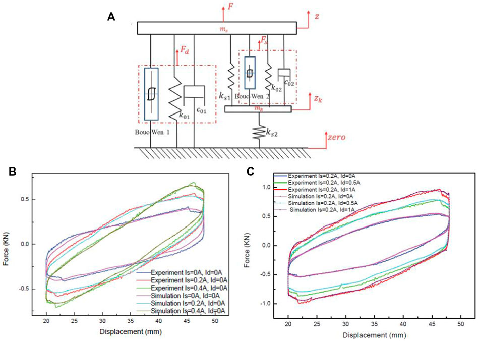
FIGURE 10. The model with two Bouc-Wen components (A) The schematic diagram. (B) Comparison of experimental and simulation results under variable stiffness. (C) Comparison of experimental and simulation results under variable damping (Sun et al., 2019).
And where:
Ad1, Ad2, β1, β2, r1 and r2 are used to describe the hysteresis behaviour; A1a, A1b, A2a, A2b, C01a, C01b, C02a and C02b are constants to be determined, C01 and C02 are viscous damping, Ks1, Ks2, K01 and K02 are the stiffness. The proposed model can predict the behaviours of the variable stiffness and damping MRF device with higher accuracy, as shown in Figures 10B,C. Compared with the Bingham model, the accuracy of the Bouc-wen model is significantly improved. However, the complexity of the model is high, and many parameters are required.
Highly nonlinear MRF dampers have variable stiffness and variable damping characteristics. The input current and other conditions change during the operation of the variable stiffness and damping MRF damper. Due to the influence of complex working conditions, the nonlinearity of dampers is also complicated. However, more solutions need to be explored to improve the model accuracy. The adaptive model is proposed to solve the problem of asymmetry and slope change. The adaptive model means that the parameters of the piecewise function model are constantly updated by a deep learning adaptive algorithm. Figure 11A shows a schematic diagram of the self-adapting model. The self-adapting model is composed of the optimization algorithm and the piecewise function model. The parameters of the piecewise function model are constantly updated by the deep learning adaptive algorithm to simplify the model and characterise the variable stiffness MRF damper. When the motion signal is applied, the motion state and damping force of the internal and external cylinders of the damper are collected to form a piecewise function model. Through the optimisation algorithm, the model parameters are adapted to reduce the difference between the measured force and the calculated force. The adaptive method can simplify the form of the model and describe the nonlinear characteristics of variable stiffness damper more accurately. Figure 11B shows the fitting results of the adaptive model to the variable stiffness characteristics. Figure 11C compares simulation results between the adaptive model and the fixed parameter model. The model with fixed parameters is difficult to fit the nonlinear curve, and there will be more errors at the inflection point. The adaptive model can describe the characteristic curve of the damper better when the current changes and has robustness. This method can be applied to dampers that require high model precision.
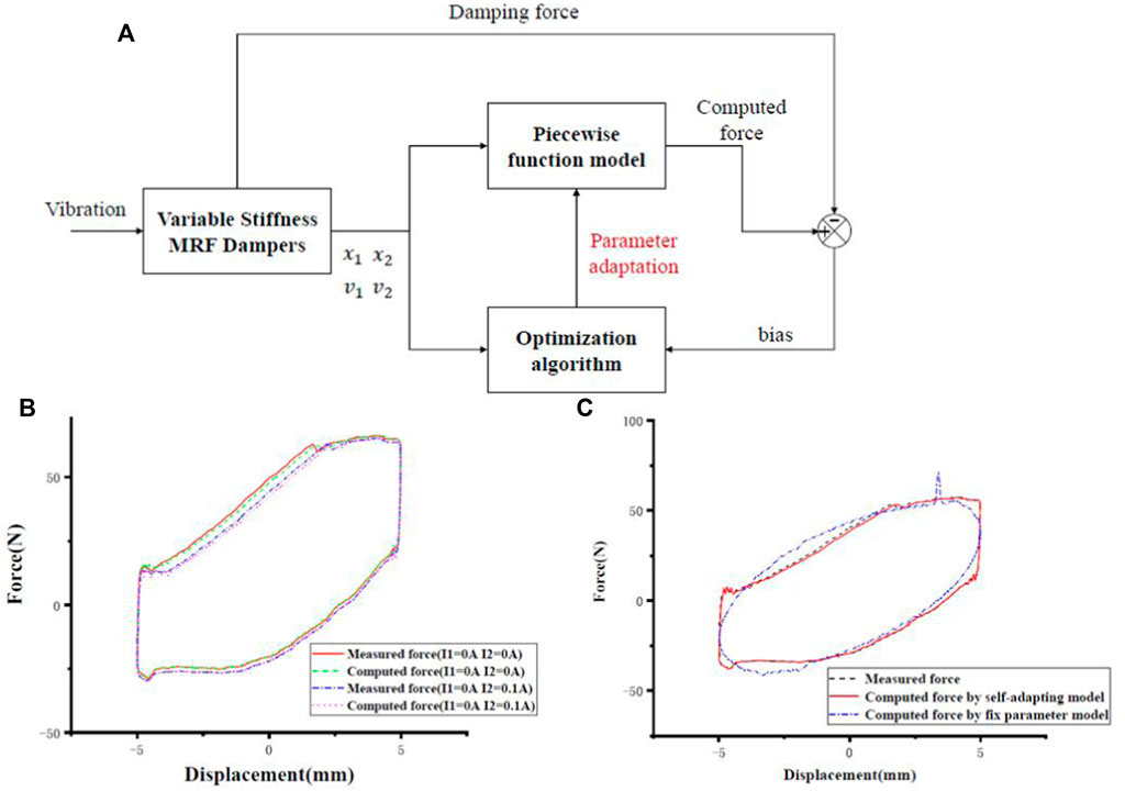
FIGURE 11. The model with Bingham components (A) The schematic diagram (Lian et al., 2021) (B) Comparison of experimental and simulation results under variable stiffness (Sun et al., 2015b) (C) Comparison of experimental and simulation results under variable damping (Sun et al., 2015b) (D) Schematic diagram of the self-adapting model (Lian et al., 2021) (E) The variable stiffness characteristic curve of damper fitted by the self-adapting model (Lian et al., 2021).
6 Applications
MRF damper can provide larger output in work, with small energy consumption, rapid response, continuously adjustable and other advantages, which have been widely used in many fields such as vehicles, machinery, construction and so on. The Lord corporation has developed a semi-active seat suspension system based on MRF dampers, which have been used in buses and trucks. The University of Maryland has developed an automotive MRF damper with an inflatable compensation structure. In 2003, Atray et al. developed a kind of MRF damper for railway vehicles and conducted a simulation study. The MRF dampers with variable stiffness and damping also have the characteristics of traditional dampers but also improve the accuracy of vibration control, further broadening the application scenarios. It is additionally applied to the lateral vibration reduction of automobiles, the vibration reduction of tanks and other vehicles under complex road conditions, and even the design of robot joints. This paper chooses the most widely used vehicle vibration reduction, for example.
A variable stiffness and damping MRF damper for the train is shown in Figure 12A, B. The utility model is mainly composed of a piston head, a piston rod, a pipe, an MR fluid accumulator, a bearing, a seal and a magnetic force generating part. The left and right movement directions of the piston head are opposite to those of the MR fluid, as shown by the red line in Figure 12A. On the bypass channel, there is a coil that can generate electromagnetic fields and affect the mechanical properties of MR fluid. A suspension structure that can effectively reduce the vibration of the tank seat is proposed as shown in Figures 12C,D. It includes a seat suspended with two variable stiffness and damping MRF dampers. When the seat vibrates vertically, relative motion will occur between the shaft and the seat, and the long suspender will better absorb energy. At the same time, by controlling the variable stiffness and damping MRF damper, the overall damping and stiffness of the seat suspension can be simultaneously controlled. Figures 13A,B show the control flow of the damper in vehicle suspension. The seat is connected to the frame by the top of the piston rods on both sides. The vertical vibration generated by the vibrating platform is applied to the seat suspension system. The control signal is derived by differentiating the corresponding displacement. These measured signals are fed back to the controller, which then outputs two desired voltage signals. The stiffness and damping of the seat are controlled by the voltage signal through the power amplifier. The seat acceleration under 1.0 Hz vibration input is shown in Figure. “Passive”, “VD” and “VSVD” indicate no control, damping control, and both damping and stiffness control respectively. The time-domain signal in Figure 13C shows that the results under VD and VSVD control are better than those under passive control. As shown in Figure 13D, the PSD of the seat acceleration under VSVD control in the frequency domain is further reduced than that under passive control or VD control. Variable damping and stiffness MR dampers have a certain advantage in the application of vehicle seats, which can be reflected in Figure 13E. The RMS of seat acceleration under VSVD control is 22.1% lower than excitation under random inputs.
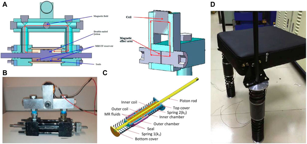
FIGURE 12. Structures of variable stiffness and damping MR damper in practical applications (A) The Cutaway view of bypass MR damper (Sun et al., 2014) (B) The structure of bypass MR damper (Sun et al., 2014) (C) The design of seat suspension damper (Deng et al., 2019) (D) The structure of seat suspension damper (Deng et al., 2019).
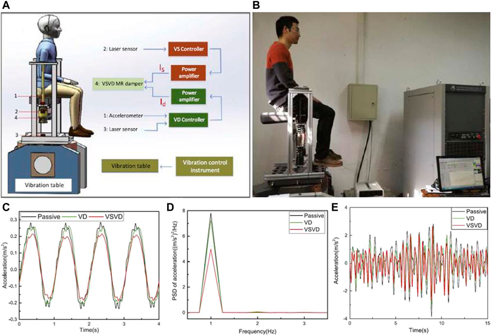
FIGURE 13. Variable stiffness dampers for vehicle suspension (A) The application and control flow (B) Comparison of experimental and simulation results under variable stiffness (C) Comparison of experimental and simulation results under variable damping (Deng et al., 2019).
Variable stiffness and damping MRF dampers have been applied in many fields and play a good ability in vibration control. It can be used for vehicle air suspension (Morales et al., 2018), controlling vehicle lateral and longitudinal stability (Xu et al., 2014; Yao et al., 2017), improving earthquake resistance of building structures (Mao and Saharabudhe, 2006), controlling the High-speed Railway Vehicle stability (Jin et al., 2020), and reducing helicopter blades vibration level (Jiang et al., 2020). Variable stiffness and damping damper can cope with the traditional vibration field control and further expand the vibration control methods, which can be used in the precision engineering and micro-vibration fields.
7 Summary and conclusion
With the continuous development of industrial engineering, the improved precision of instruments and equipment requires a higher standard for vibration control strategy in the working environment. The variable stiffness and damping MRF dampers have unique advantages in many engineering scenarios. The variable stiffness and variable damping functions are integrated into the same vibration control device, which can reduce the vibration controller’s volume, improve the controller’s performance, and provide more methods for the vibration control scheme. The development of variable stiffness and variable damping technology can improve the control accuracy of semiactive dampers, to make the traditional dampers have the potential to be applied in precision engineering and micro-vibration control. In addition, considering the development needs and potential value of dampers in various fields such as micro-vibration and robotics, it is necessary to improve the control algorithm of dampers and combine it with machine learning to continuously improve the vibration control accuracy of this variable stiffness and damping MRF dampers.
The systematic overview of the variable stiffness and damping MRF damper is presented in detail in this review, including the response characteristics of the damper under different conditions, development of the damper structures, methods of damper modelling, and the application examples. In general, research on variable stiffness and damping MR dampers is mainly focused on structural improvement to cope with different working environments. For the development of variable stiffness and variable damping MR dampers, the following conclusions can be drawn:
i) Variable stiffness and damping MR dampers can play an important role in vibration control in simulation engineering scenarios and have a wide ability to adjust the damping and stiffness.
ii) Some models have been proposed, but there is no relatively simple high-precision parametric model to describe such complex nonlinear characteristics.
iii) The inverse parameter dynamics model is of much concern in the application of dampers. The current research is not mature and needs to be further developed.
iv) The variable stiffness and damping MR damper needs to be further explored in practical engineering applications.
Author contributions
HD: Conceptualization, Writing—review and editing. XL: Investigation, Conceptualization, Writing—Original Draft. XG: Supervision.
Funding
This work is supported by the National Natural Science Foundation of China (Grant Nos. 11872167 and 51775164) and the Natural Science Foundation of Anhui Province (1908085J15).
Conflict of interest
The authors declare that the research was conducted in the absence of any commercial or financial relationships that could be construed as a potential conflict of interest.
Publisher’s note
All claims expressed in this article are solely those of the authors and do not necessarily represent those of their affiliated organizations, or those of the publisher, the editors and the reviewers. Any product that may be evaluated in this article, or claim that may be made by its manufacturer, is not guaranteed or endorsed by the publisher.
References
Ahn, Y. K., Yang, B.-S., Ahmadian, M., and Morishita, S. (2005). A small-sized variable-damping mount using magnetorheological fluid. J. Intelligent Material Syst. Struct. 16, 127–133. doi:10.1177/1045389X05048041
Çeşmeci, Ş., and Engin, T. (2010). Modeling and testing of a field-controllable magnetorheological fluid damper. Int. J. Mech. Sci. 52, 1036–1046. doi:10.1016/j.ijmecsci.2010.04.007
Deng, H., Deng, J., Yue, R., Han, G., Zhang, J., Ma, M., et al. (2019). Design and verification of a seat suspension with variable stiffness and damping. Smart Mat. Struct. 28, 065015. doi:10.1088/1361-665x/ab18d4
Deng, H., and Gong, X. (2007). Adaptive tuned vibration absorber based on magnetorheological elastomer. J. Intelligent Material Syst. Struct. 18, 1205–1210. doi:10.1177/1045389X07083128
Deng, H., Wang, M., Han, G., Zhang, J., Ma, M., Zhong, X., et al. (2017). Variable stiffness mechanisms of dual parameters changing magnetorheological fluid devices. Smart Mat. Struct. 26, 125014. doi:10.1088/1361-665x/aa92d5
Dong, X.-m. (2013). Semi-active control of magneto-rheological variable stiffness and damping seat suspension with human-body model. Int. J. Veh. Des. 63, 119–136. doi:10.1504/ijvd.2013.056098
Du, H., Li, W., and Zhang, N. (2011). Semi-active variable stiffness vibration control of vehicle seat suspension using an MR elastomer isolator. Smart Mat. Struct. 20, 105003. doi:10.1088/0964-1726/20/10/105003
Eem, S. H., Jung, H. J., and Koo, J. H. (2013). Seismic performance evaluation of an MR elastomer-based smart base isolation system using real-time hybrid simulation. Smart Mat. Struct. 22, 055003. doi:10.1088/0964-1726/22/5/055003
Genc, S. (2022). “Experimental studies on magnetorheological fluids,” in Encyclopedia of Smart materials. Editor A.-G. Olabi (Oxford: Elsevier), 248–259. doi:10.1016/B978-0-12-803581-8.12095-8
Guan, X., Dong, X., and Ou, J. (2008). Magnetostrictive effect of magnetorheological elastomer. J. Magnetism Magnetic Mater. 320, 158–163. doi:10.1016/j.jmmm.2007.05.043
Guo, C., Gong, X., Zong, L., Peng, C., and Xuan, S. (2015). Twin-tube- and bypass-containing magneto-rheological damper for use in railway vehicles. Proc. Institution Mech. Eng. Part F J. Rail Rapid Transit 229, 48–57. doi:10.1177/0954409713497199
Huang, H., Sun, S., Chen, S., and Li, W. (2019). Numerical and experimental studies on a new variable stiffness and damping magnetorheological fluid damper. J. Intelligent Material Syst. Struct. 30, 1639–1652. doi:10.1177/1045389X19844003
Jiang, R., Rui, X., Wang, G., Yang, F., Zhu, W., and Wei, M. (2020). Design and modeling of an innovative magnetorheological fluid-elastomeric damper with compact structure. J. Intelligent Material Syst. Struct. 31, 2088–2100. doi:10.1177/1045389X20942898
Jin, T., Liu, Z., Sun, S., Ren, Z., Deng, L., Yang, B., et al. (2020). Development and evaluation of a versatile semi-active suspension system for high-speed railway vehicles. Mech. Syst. Signal Process. 135, 106338. doi:10.1016/j.ymssp.2019.106338
Kim, Y., Langari, R., and Hurlebaus, S. (2009). Semiactive nonlinear control of a building with a magnetorheological damper system. Mech. Syst. Signal Process. 23, 300–315. doi:10.1016/j.ymssp.2008.06.006
Li, W., Zhang, X., Tian, T., and Wen, W. (2013). Fabrication and characterisation of patterned magnetorheological elastomers. AIP Conf. Proc. 1542, 129–132. doi:10.1063/1.4811884
Li, W., Zhou, Y., and Tian, T. (2010). Viscoelastic properties of mr elastomers under harmonic loading. Rheol. Acta 49, 733–740. doi:10.1007/s00397-010-0446-9
Lian, X., Deng, H., Han, G., Ma, M., Zhong, X., Gao, Y., et al. (2021). Self-adapting model for variable stiffness magnetorheological dampers. Smart Mat. Struct. 31, 025006. doi:10.1088/1361-665x/ac3f79
Liao, G. J., Gong, X.-L., Xuan, S. H., Kang, C. J., and Zong, L. H. (2012). Development of a real-time tunable stiffness and damping vibration isolator based on magnetorheological elastomer. J. Intelligent Material Syst. Struct. 23, 25–33. doi:10.1177/1045389X11429853
Liu, Y., Matsuhisa, H., Utsuno, H., and Park, J. G. (2006). Variable damping and stiffness vibration control with magnetorheological fluid dampers for two degree-of-freedom system. JSME Int. J. Ser. C 49, 156–162. doi:10.1299/jsmec.49.156
Liu, Y., Matsuhisa, H., and Utsuno, H. (2008). Semi-active vibration isolation system with variable stiffness and damping control. J. Sound Vib. 313, 16–28. doi:10.1016/j.jsv.2007.11.045
Mao, Y., and Saharabudhe, S. (2006). Nonlinear, seismic response spectra of smart sliding isolated structures with independently variable mr dampers and variable stiffness savs system. Struct. Eng. Mech. 24, 375–393. doi:10.12989/SEM.2006.24.3.375
Marathe, S., Gandhi, F., and Wang, K.-W. (1998). Helicopter blade response and aeromechanical stability with a magnetorheological fluid based lag damper. J. Intell. Mat. Syst. Struct. 3329, 272–282. doi:10.1177/1045389X9800900405
Morales, A. L., Nieto, A. J., Chicharro, J. M., and Pintado, P. (2018). A semi-active vehicle suspension based on pneumatic springs and magnetorheological dampers. J. Vib. Control 24, 808–821. doi:10.1177/1077546316653004
Opie, S., and Yim, W. (2009). Design and control of a real-time variable stiffness vibration isolator. In 2009 IEEE/ASME International Conference on Advanced Intelligent Mechatronics. 14-17 July 2019, Singapore, 380–385. doi:10.1109/AIM.2009.5229983
Parlak, Z., Engin, T., and İsmail, Ç. (2012). Optimal design of mr damper via finite element analyses of fluid dynamic and magnetic field. Mechatronics (Oxf).Special Issue Intelligent Mechatronics (LSMS2010 ICSEE2010) 22, 890–903. doi:10.1016/j.mechatronics.2012.05.007
Parlak, Z., Engin, T., and Sahin, I. (2013). Optimal magnetorheological damper configuration using the taguchi experimental design method. J. Mech. Des. 135, 081008. doi:10.1115/1.4024719
Parlak, Z., and Engin, T. (2012). Time-dependent cfd and quasi-static analysis of magnetorheological fluid dampers with experimental validation. Int. J. Mech. Sci. 64, 22–31. doi:10.1016/j.ijmecsci.2012.08.006
Ruan, X., Xuan, S., Zhao, J., Bian, H., and Gong, X. (2020). Mechanical performance of a novel magnetorheological fluid damper based on squeeze-valve bi-mode of MRF. Smart Mat. Struct. 29, 055018. doi:10.1088/1361-665x/ab7e34
Şahin, İ., Engin, T., and Çeşmeci, Ş. (2010). Comparison of some existing parametric models for magnetorheological fluid dampers. Smart Mat. Struct. 19, 035012. doi:10.1088/0964-1726/19/3/035012
Şahin, Ö., Gökhan Adar, N., Kemerli, M., Çaglar, N., İsmail, Ş., Parlak, Z., et al. (2021). A comparative evaluation of semi-active control algorithms for real-time seismic protection of buildings via magnetorheological fluid dampers. J. Build. Eng. 42, 102795. doi:10.1016/j.jobe.2021.102795
Song, X., Ahmadian, M., and Southward, S. (2003). An adaptive semiactive control algorithm for vehicle suspension systems. Proceedings of the ASME International Mechanical Engineering Congress and Exposition, Washington, DC, January 2003, 219–228. doi:10.1115/IMECE2003-43566
Sun, S., Deng, H., Du, H., Li, W., Yang, J., Liu, G., et al. (2015a). A compact variable stiffness and damping shock absorber for vehicle suspension. Ieee. ASME. Trans. Mechatron. 20, 2621–2629. doi:10.1109/TMECH.2015.2406319
Sun, S., Deng, H., and Li, W. (2014). “Variable stiffness and damping suspension system for train,” in Active and passive Smart structures and integrated systems 2014. Editor W.-H. Liao (Bellingham, Washington, United States: International Society for Optics and Photonics SPIE), 9057, 234–242. doi:10.1117/12.2045023
Sun, S., Tang, X., Li, W., and Du, H. (2017). Advanced vehicle suspension with variable stiffness and damping mr damper. In Proceedings of the 2017 IEEE International Conference on Mechatronics (ICM). 13-15 Feb. 2017, Churchill, VIC, Australia, 444–448. doi:10.1109/ICMECH.2017.7921148
Sun, S., Tang, X., Yang, J., Ning, D., Du, H., Zhang, S., et al. (2019). A new generation of magnetorheological vehicle suspension system with tunable stiffness and damping characteristics. IEEE Trans. Ind. Inf. 15, 4696–4708. doi:10.1109/tii.2018.2890290
Sun, S., Yang, J., Li, W., Deng, H., Du, H., and Alici, G. (2015b). Development of a novel variable stiffness and damping magnetorheological fluid damper. Smart Mat. Struct. 24, 085021. doi:10.1088/0964-1726/24/8/085021
Tang, X., Ning, D., Du, H., Li, W., Gao, Y., and Wen, W. (2020). A takagi-sugeno fuzzy model-based control strategy for variable stiffness and variable damping suspension. IEEE Access 8, 71628–71641. doi:10.1109/ACCESS.2020.2983998
Wang, D. H., and Liao, W. H. (2011). Magnetorheological fluid dampers: A review of parametric modelling. Smart Mat. Struct. 20, 023001. doi:10.1088/0964-1726/20/2/023001
Wang, Q., Dong, X., Li, L., and Ou, J. (2017). Study on an improved variable stiffness tuned mass damper based on conical magnetorheological elastomer isolators. Smart Mat. Struct. 26, 105028. doi:10.1088/1361-665x/aa81e8
Wang, Q., Dong, X., Li, L., Yang, Q., and Ou, J. (2020). Wind-induced vibration control of a constructing bridge tower with MRE variable stiffness tuned mass damper. Smart Mat. Struct. 29, 045034. doi:10.1088/1361-665x/ab785a
Wasiwitono, U. W., Pramono, A. S., Sutantra, I. N., and Triwinarno, Y. (2016). Influence of spring ratio on variable stiffness and damping suspension system performance. Appl. Mech. Mater. 836, 31–36. doi:10.4028/www.scientific.net/AMM.836.31
Xu, Y., and Ahmadian, M. (2013). Improving the capacity of tire normal force via variable stiffness and damping suspension system. J. Terramechanics 50, 121–132. doi:10.1016/j.jterra.2013.03.003
Xu, Y., Ahmadian, M., and Sun, R. (2014). Improving vehicle lateral stability based on variable stiffness and damping suspension system via mr damper. IEEE Trans. Veh. Technol. 63, 1071–1078. doi:10.1109/TVT.2013.2282824
Yang, J., Sun, S., Tian, T., Li, W., Du, H., Alici, G., et al. (2016). Development of a novel multi-layer mre isolator for suppression of building vibrations under seismic events. Mech. Syst. Signal Process. 70-71, 811–820. doi:10.1016/j.ymssp.2015.08.022
Yao, G., Yap, F., Chen, G., Li, W., and Yeo, S. (2002). Mr damper and its application for semi-active control of vehicle suspension system. Mechatronics 12, 963–973. doi:10.1016/S0957-4158(01)00032-0
Yao, J., Lv, G., Qv, M., Li, Z., Ren, S., and Taheri, S. (2017). Lateral stability control based on the roll moment distribution using a semiactive suspension. Proc. Institution Mech. Eng. Part D J. Automob. Eng. 231, 1627–1639. doi:10.1177/0954407016681386
Yu, J., Dong, X., Qi, S., Wang, T., and Liang, Y. (2021). Development of a magnetorheological isolator with variable damping and variable stiffness for broadband vibration suppression. Smart Mat. Struct. 30, 025023. doi:10.1088/1361-665x/abd4fc
Zhang, X., Li, W., and Zhou, Y. (2009). A variable stiffness mr damper for vibration suppression. In Proceeding of the 2009 IEEE/ASME International Conference on Advanced Intelligent Mechatronics. 14-17 July 2019, Singapore, 106–111. doi:10.1109/AIM.2009.5230029
Keywords: variable stiffness, variable damping, magnetorheological damper, semi active, control
Citation: Deng H, Lian X and Gong X (2022) A brief review of variable stiffness and damping magnetorheological fluid dampers. Front. Mater. 9:1019426. doi: 10.3389/fmats.2022.1019426
Received: 15 August 2022; Accepted: 14 September 2022;
Published: 12 October 2022.
Edited by:
Tongfei Tian, University of the Sunshine Coast, AustraliaReviewed by:
Nanthakumar Ajd, SRM Institute of Science and Technology, IndiaTahsin Engin, Istanbul Technical University, Turkey
Copyright © 2022 Deng, Lian and Gong. This is an open-access article distributed under the terms of the Creative Commons Attribution License (CC BY). The use, distribution or reproduction in other forums is permitted, provided the original author(s) and the copyright owner(s) are credited and that the original publication in this journal is cited, in accordance with accepted academic practice. No use, distribution or reproduction is permitted which does not comply with these terms.
*Correspondence: Huaxia Deng, aHhkZW5nQHVzdGMuZWR1LmNu; Xinglong Gong, Z29uZ2x4QHVzdGMuZWR1LmNu
†These authors have contributed equally to this work and share first authorship