 Song Chen
 Zhao Yang3
 Liufang Li
95% of researchers rate our articles as excellent or good
Learn more about the work of our research integrity team to safeguard the quality of each article we publish.
Find out more
ORIGINAL RESEARCH article
Front. Mater. , 21 September 2022
Sec. Structural Materials
Volume 9 - 2022 | https://doi.org/10.3389/fmats.2022.1007855
This article is part of the Research Topic Physico-Mechanical Properties and Treatment Technology of Hazardous Geomaterials View all 23 articles
Tunnel construction in China is increasing year by year. With the passage of time, China will usher in the peak period of tunnel engineering repair, and it is vital to study in advance the influential nature of tunnel lining crack disease as well as management measures. By summarising a large amount of relevant literature, this paper analyses the main locations where cracks are generated in tunnel linings. Through the method of finite element numerical analysis, 24 cases of cracks of different widths and depths were modelled and calculated for each location of lining vaults, shoulders and side walls, respectively, to analyse the influence of different cases on the internal forces and deformation of the lining. The study shows that the stress concentration around the crack tip decreases with the increase of the crack width, while the stress concentration around the crack tip increases with the increase of the crack depth. The stresses in the other main parts of the lining increase after the crack is created, which has a deteriorating effect on the load-bearing capacity and stability of the lining structure. With the increase in crack width and depth, the sinking deformation of the vault and the heaving deformation of the back arch increase, especially when the cracks are large, but lining cracking has less effect on the lateral deformation of the lining. Compared to cracks in the top and shoulder of the arch, cracks in the side walls have a more pronounced effect on the distribution of internal forces around the cracks.
In recent years, with the rapid development of China’s economy, the construction of road traffic projects in China is increasing year by year. In addition, China’s geological conditions are complex and varied, and the southwest region is mountainous and hilly, so a large number of tunnel projects are put into construction. However, due to the complex geological environment of the tunnel and the influence of design and construction, The stability of the project is influenced by many factors. Among them, theoretical analysis (Bai et al., 2019; Bai et al., 2021a; Bai et al., 2022), environmental simulation experiments (Hu et al., 2021), artificial intelligence algorithms (Bai et al., 2021b; Bai et al., 2021c) and other technologies are widely used in the analysis of related issues.
There will be many diseases in the tunnel lining in the later period of use. With the passage of time, China will shift from the peak period of construction to the peak period of maintenance, so it is very important to carry out tunnel disease research before understanding and reserving technology. Among many diseases of tunnel lining, lining cracks is the most common, which seriously affect the bearing capacity and safety performance of lining. Therefore, the analysis of the causes of tunnel lining cracks and the impact of cracks on the overall stability of lining structure is a hot issue in current research (Zhang et al., 2007).
Scholars had done relevant researches on the problem of lining cracks. Chen and Mo (2009) established the shield tunnel model by finite element method, analyzed the cracking situation of segments in the later tunnel operation, summarized the easy cracking positions of segments and gave prevention suggestions. Ye et al. (2010) made statistics on the crack parameters of a large number of actual tunnels, and combined with design and construction records and numerical analysis results, analyzed various causes of lining cracks, and at the same time, gave safety diagnosis and evaluation for typical crack tracking and monitoring research. Huang et al. (2013) used extended finite element analysis to study the distribution law, cracking mechanism and crack forms of lining cracks under the influence of main causes of highway tunnels in Zhejiang. Briffaut et al. (2016) have studied the sensitivity and influence of different types of fibers on the early cracking of concrete lining through laboratory tests and numerical simulations. The results show that polypropylene coarse fiber and steel fiber can delay the cracking time and reduce the influence of cracking, and changing the fiber type and thickness of secondary lining can help to reduce the transverse cracking. Asad and Majid (2017) has been experimentally demonstrated that building materials such as nylon fiber reinforced concrete can reduce the crack rate in pipeline lining due to alternating wetting and subsidence. Liu et al. (2017) analyzed the lining section defects through the ground penetrating radar (GPR) antenna detection test, summarized the waveform and frequency spectrum characteristics of the defects, and put forward the method of determining the zero line position of radar wave by using the reflection hyperbola of point objects to invert the velocity and then calculate the lining thickness, which can help identify the lining defect types. Fu et al. (2021) conducted experiments and engineering investigations on shrinkage characteristics of lined machine-made sand concrete, gave the differences between machine-made sand concrete and river sand concrete in mechanical properties and shrinkage deformation, and analyzed the causes of circumferential cracking caused by machine-made sand concrete. Xu et al. (2021, 2022) developed a similar material to simulate the cracking of surrounding rock and lining, which can effectively simulate the development and evolution of cracks. Then, the mechanical properties and cracking characteristics of lining under the coupling action of temperature and load were studied by using an independently developed tunnel geomechanics model test system. Zhang et al. (2022a) obtained the damage constitutive parameters required for theoretical research through three kinds of fiber concrete tests combined with DIC technology, and analyzed the influence law of different crack position, inclination angle, vehicle speed and other parameters on the safety and stability of the lined lining with joints under the conditions of conventional concrete and different fiber concrete by finite element displacement method. Zhang Z. Q. et al. (2022) studied the mechanics and deformation characteristics, stress distribution, crack development and failure mechanism of tunnel lining in water-rich layer through large-scale model experiments. Zhang et al. (2022c) studied the deterioration process of tunnel drainage system and the failure mechanism of lining through field investigation and numerical simulation analysis based on cracks.
In this paper, the causes and main distribution positions of lining cracking are analyzed, and the influence of different positions of lining cracking on the stress and deformation of lining structure is analyzed by numerical simulation. This analysis will help to improve the understanding of the influence of lining crack diseases, and give some enlightenment to the later monitoring and maintenance, stability evaluation and reinforcement and repair of tunnel lining.
Cracks in any part of the lining can affect the safety of the tunnel. Studies have shown that lining cracks are mainly concentrated in the vault, shoulder and sidewall areas, as shown in Figure 1 Cracks in these parts of the tunnel have a more significant impact on the lining forces, and the threat to the overall tunnel lining safety is more obvious when the cracks expand in large numbers (Yuan, 2019).
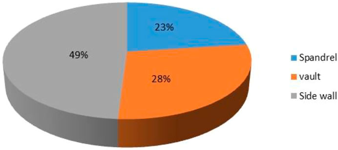
FIGURE 1. Statistical diagram of main distribution positions of lining cracks.
The “stratum structure” model can better simulate the interaction between stratum and structure than the “load structure” model. This paper mainly studies the influence of the existing cracks on the internal force and deformation of the lining structure. When establishing the model, the boundary situation is considered to be similar to the actual situation as much as possible, so the “stratum structure” model is more appropriate. In the numerical simulations, cracks in the tunnel lining are simulated by removing the grid cells at the predetermined cracks to achieve a similar effect to the actual situation.
This paper is based on the G4216 Chengdu-Lijiang National Expressway, Huaping-Lijiang section, a deeply buried tunnel in the Yingpan Mountains with complex topography, geology, environment and construction conditions, an average burial depth of about 600 m and a tunnel width of 11 m.
As the spatial effect of the surrounding rock after tunnel excavation is to be considered, the boundary dimensions of the built model contain three times the tunnel bore diameter range (Su, 2012). Taking into account the model’s aspect ratio, the tunnel model was determined to have a vault depth of 100m, with the rest of the upper rock being replaced by a corresponding stress boundary, with a model aspect ratio of 44 × 135.16 m. The model is divided into a total of 5,020 meshes, the boundary conditions are set to the left and right boundaries of the horizontal direction constraints, the upper ground constraints for the 500 m surrounding rock self-weight stress 10000 kN/m (Zhang et al., 2018), The lower boundary is fully constrained. The Mohr-Coulomb criterion was chosen for the intrinsic structure of the surrounding rock and the elastic intrinsic structure model was chosen for the tunnel lining intrinsic structure. Figure 2 shows the model and Figure 3 shows the tunnel lining structure. Based on the tunnel design and relevant geological exploration data and relevant national code standards, the material parameters selected for the numerical simulation are shown in Table 1.
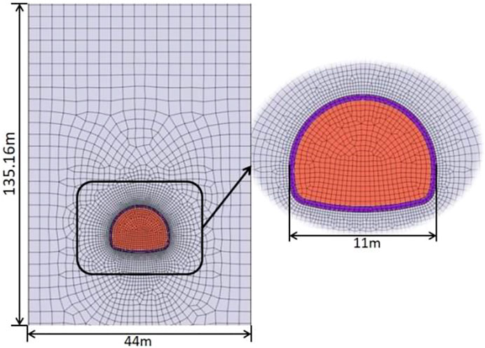
FIGURE 2. Numerical calculation model
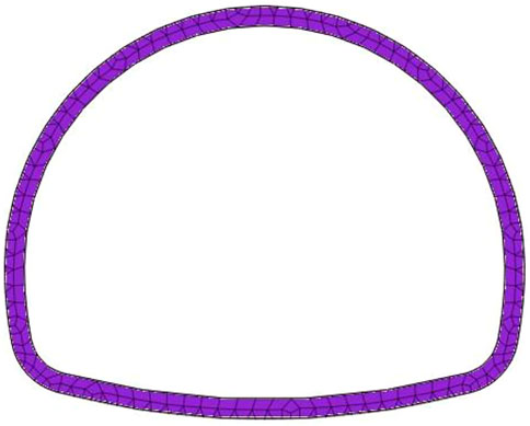
FIGURE 3. Tunnel lining structure
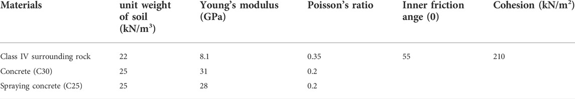
TABLE 1. Physical and mechanical parameters of materials.
Firstly, a crack-free lining model is established for numerical analysis as a control group. Then, according to China’s Technical Manual of Railway Public Works, the lining cracks are divided into four levels (see Table 2 for details), and the cracks with different widths of 0.3, 2, 10 and 20 mm and different depths of 10, 20, 30 and 40 cm (Xiao et al., 2021) are set on the inside of vault, arch shoulder and side wall respectively. A total of 24 simulation schemes are set according to different positions, widths and depths of lining cracks (see Table 3). The influence of different crack positions, different crack widths and depths on the stress and deformation of tunnel lining structure is analyzed.
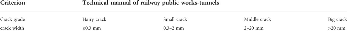
TABLE 2. Quantitative evaluation criteria of lining cracks.

TABLE 3. Simulation schemes.
The numerical model of undamaged lining is established, and its internal force and deformation are analyzed as the control group, and compared with the following different lining cracking models.
It can be seen from the numerical simulation cloud chart in Figure 4 that the maximum tensile stress of the undamaged lining is mainly distributed outside the vault and arch shoulder, while the maximum compressive stress is mainly concentrated outside the inverted arch and the wall foot of the tunnel, and the internal force are basically symmetrically distributed. Generally, the stress on the outside of the whole lining structure is higher than that on the inside of the lining, but the maximum tensile stress and the maximum compressive stress do not exceed the tensile strength and compressive strength of concrete, so the lining structure is in a safe and stable state.
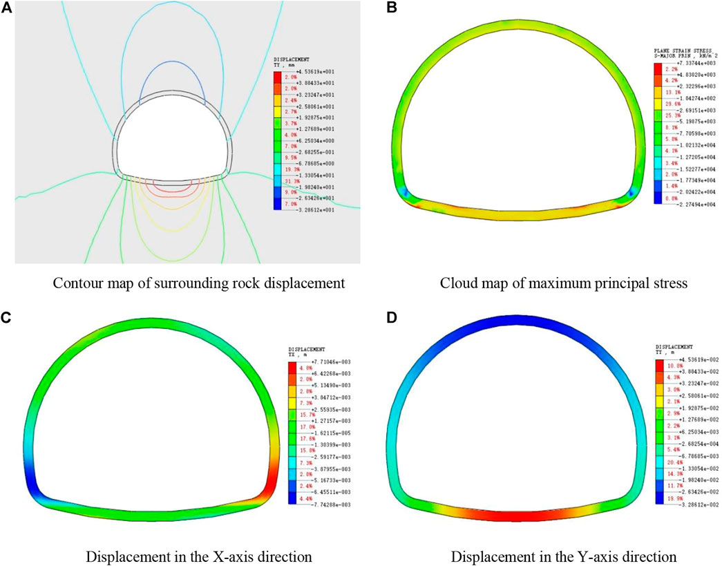
FIGURE 4. Numerical analysis results of undamaged lining model. (A) Contour map of surrounding rock displacement. (B) Cloud map of maximum principal stress. (C) Displacement in the X-axis direction. (D) Displacement in the Y-axis direction
From the displacement nephogram, it can be seen that the tunnel lining deformation mainly includes vault subsidence, inverted arch uplift and horizontal deformation of two side walls, and the maximum vertical deformation mainly occurs in the middle of the vault and inverted arch, which accords with the actual deformation of tunnel engineering and verifies the rationality of the model.
As shown in Figures 5, 6, the crack tip of lining mainly bears compressive stress, and both sides of the crack are mainly tensile stress, and the maximum stress value is concentrated at the crack tip, which exceeds the compressive strength of concrete, that is, once cracks are generated in lining, there will be an expansion trend. When the depth of lining crack is constant, with the increase of vault crack width, the tensile stress and compressive stress at the crack are decreasing, because the stress concentration at the crack is weakening with the crack expansion. As shown in Figure 6, with the increase of crack width, the integrity of the lining structure is destroyed to a certain extent, which will weaken the bearing capacity of the lining structure. The stress at the main position of the lining is constantly increasing, especially the internal force at the foot of the wall is significantly increased. Except for the cracks, the whole lining structure is still in a safe working state.
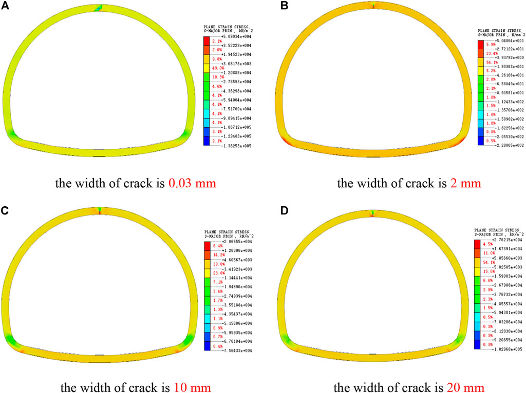
FIGURE 5. Cloud map of major principal stress of vault crack. (A) The width of crack is 0.03 mm. (B) The width of crack is 2 mm. (C) The width of crack is 10 mm. (D) The width of crack is 20 mm.
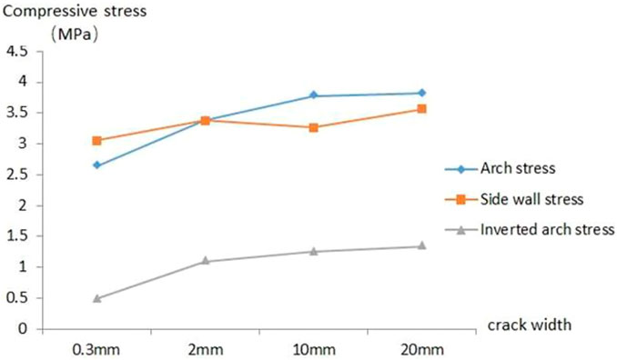
FIGURE 6. Stress variation diagram of main position of cracked lining of vault
As shown in Figure 7, the vertical displacement of the lining arch increases after the lining vault cracks, which aggravates the phenomenon of vault subsidence, which is not conducive to the stability of the lining. At the same time, with the increase of crack width, compared with the undamaged lining, the vertical displacement of inverted arch slightly increases, which shows that the influence of vault cracking on the vertical deformation of lining is mainly concentrated around the arch of lining.
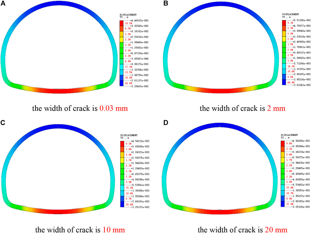
FIGURE 7. Cloud picture of Y-direction displacement of vault crack lining. (A) The width of crack is 0.03 mm. (B) The width of crack is 2 mm. (C) The width of crack is 10 mm. (D) The width of crack is 20 mm.
As shown in Figure 8, the stress value around the arch shoulder crack is obviously larger than that around the vault crack, and the crack tip is damaged by compression, and the stress concentration range caused by the arch shoulder crack is larger, so the arch shoulder crack damages the lining more than the vault crack. With the increase of crack width, the stress at the crack decreases, and the crack propagation rate will decrease, but the internal forces of other main parts of the lining increase, as shown in Figure 9.
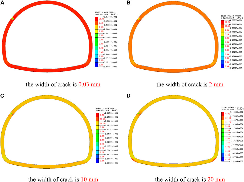
FIGURE 8. Cloud picture of large principal stress of arch shoulder crack, (A) the width of crack is 0.03 mm. (B) The width of crack is 2 mm. (C) The width of crack is 10 mm. (D) The width of crack is 20 mm.
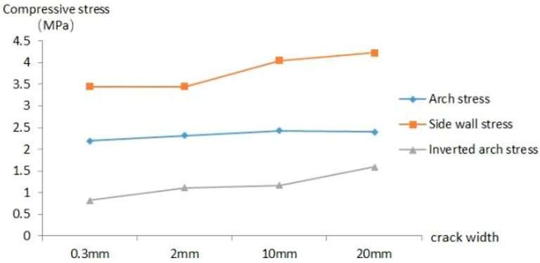
FIGURE 9. Stress variation diagram of main position of arch shoulder cracked lining
When the crack width is 20 mm, the stress value at the outer edge of the lining at the crack reaches about 20MPa, which is close to the compressive strength of concrete. At this time, the safety of the lining structure has been greatly affected, and the reinforcement and repair measures should be taken in time. When there is a large crack larger than 10mm, the internal force of the cracked side wall is increased by the arch shoulder crack, but the law is not obvious when there is a small crack.
As shown in Figure 10, the cracking of the lining arch shoulder will increase the vertical deformation of the lining and aggravate the arch subsidence and inverted arch uplift. With the continuous expansion of crack width, the vertical settlement deformation of vault and the uplift deformation of inverted arch are increasing, especially when the crack width exceeds 10mm, the deformation is more obvious, which has a certain deterioration effect on the lining structure. At this time, monitoring should be strengthened or repair measures should be taken to ensure the bearing safety.
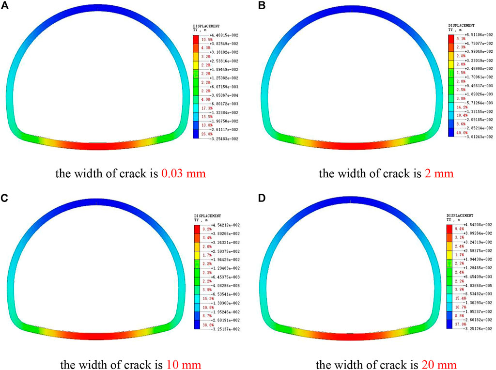
FIGURE 10. Cloud picture of Y-direction displacement of arch shoulder crack lining. (A) The width of crack is 0.03 mm. (B) The width of crack is 2 mm. (C) The width of crack is 10 mm. (D) The width of crack is 20 mm.
As shown in Figure 11, the stress at the crack of the lining side wall is obviously greater than that at other parts of the lining, and the stress concentration phenomenon is very obvious. Comparing Figure 5 and Figure 8, it can be seen that after the lining side wall cracks, the stress around the cracks increases significantly more than that at the lining vault and arch shoulder. When the side wall crack is less than 10 mm, the stress at the bottom of the crack is greater than the strength of the concrete, and the stress at other parts is in a safe bearing state.
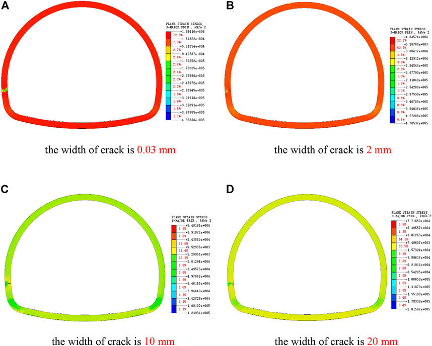
FIGURE 11. Cloud picture of maximum principal stress of side wall cracks. (A) The width of crack is 0.03 mm. (B) The width of crack is 2 mm. (C) The width of crack is 10 mm. (D) The width of crack is 20 mm.
As shown in Figure 12, after the side wall cracks, the side wall gradually changes from the compression state to the tension state. When the crack width reaches 20 mm wide, the compressive stress on the outside of the lining and the tensile stress on the side wall of the crack will soon reach the compressive strength and tensile strength of concrete, which indicates that the local concrete at the crack of the lining side wall will be crushed at this time, and the safety of the lining side wall can no longer be guaranteed. Therefore, reinforcement and repair should be carried out in time to prevent the lining structure from being unstable and damaged.
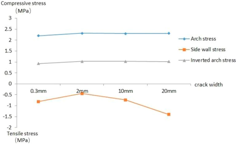
FIGURE 12. Stress variation diagram of main position of cracked lining of side wall
As shown in Figure 13, the vertical settlement deformation of the lining at the crack will be increased after the side wall cracks. For the lining structure, the vertical deformation of other parts has little influence. Compared with the undamaged lining, the side wall cracks will increase the settlement deformation of the vault, but the increased value is very small. It can be seen that the influence of side wall lining cracks on the vertical deformation of lining is mainly concentrated around the cracks.
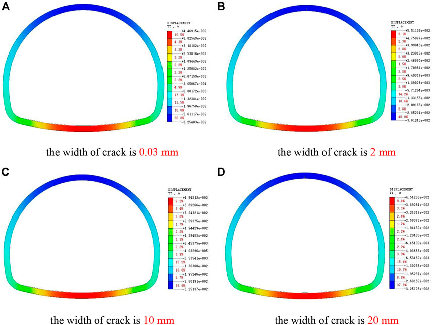
FIGURE 13. Cloud pictures of Y-direction displacement of side wall crack lining. (A) The width of crack is 0.03 mm. (B) The width of crack is 2 mm. (C) The width of crack is 10 mm. (D) The width of crack is 20 mm.
As shown in Figure 14, when the lining vault cracks, the stress of the lining structure is symmetrically distributed, and obvious stress concentration occurs near the crack tip. With the increase of crack depth, the maximum stress around the crack tip is increasing. When the crack depth is greater than 30 cm, the damage range of compressive stress at the crack tip is close to the lining edge, and the lining stability cannot be guaranteed. Therefore, reinforcement and repair measures should be taken in time.
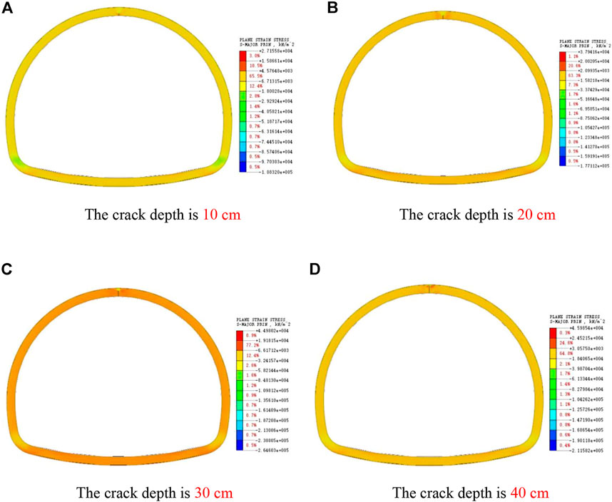
FIGURE 14. Cloud pictures of maximum principal stress of cracks at different depths in vault. (A) The crack depth is 10 cm. (B) The crack depth is 20 cm. (C) The crack depth is 30 cm. (D) The crack depth is 40 cm.
As shown in Figure 15, with the increase of vault crack depth, the vertical displacement of the lining structure vault increases, but the increased value is relatively small, and the main influence range is concentrated near the vault crack, while the vertical displacement of other main parts has no obvious effect.
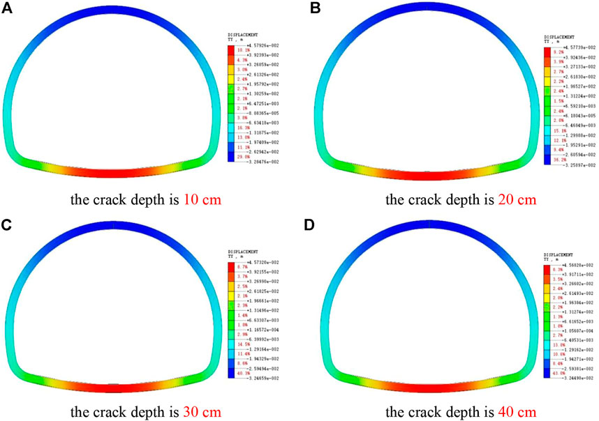
FIGURE 15. Picture of Y-direction displacement of cracked lining at different depths of vault. (A) The crack depth is 10 cm. (B) The crack depth is 20 cm. (C) The crack depth is 30 cm. (D) The crack depth is 40 cm.
As shown in Figure 16, when the arch shoulder cracks, the stress value around the crack is obviously higher than that of the vault crack, and the stress concentration around the crack is larger, indicating that the arch shoulder is more sensitive to the change of crack depth, that is, the arch shoulder crack is more destructive to the lining than the vault crack. With the increase of crack depth, the stress around the crack increases continuously. When the crack depth is more than 30 cm, the compressive stress of the lining edge near the crack tip has reached the compressive strength of concrete, and the safety and stability of the arch shoulder of the lining structure cannot be guaranteed. Therefore, it is necessary to strengthen the monitoring of the cracks at the arch shoulder to ensure timely repair and reinforcement.
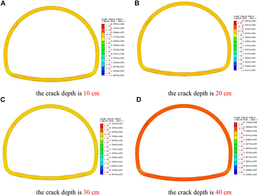
FIGURE 16. Cloud pictures of maximum principal stress of cracks at different depths in arch shoulder. (A) The crack depth is 10 cm. (B) The crack depth is 20 cm. (C) The crack depth is 30 cm. (D) The crack depth is 40 cm.
From Figure 17, the vertical deformation of the lining will be increased when cracks appear in the arch shoulder, and the settlement displacement around the vault will increase with the increase of the crack depth, but the increment will be small. Compared with the undamaged lining, the arch shoulder crack also increases the uplift displacement of the inverted arch.
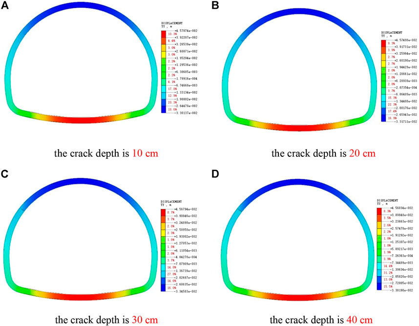
FIGURE 17. Cloud image of Y-direction displacement of lining with cracks at different depths in arch shoulder. (A) The crack depth is 10 cm. (B) The crack depth is 20 cm. (C) The crack depth is 30 cm. (D) The crack depth is 40 cm.
As shown in Figure 18, the stress around the crack at the side wall increases obviously, and the stress around the crack is larger than that in the vault and arch shoulder, which is more sensitive to the depth factor. When the side wall crack is larger than 30 cm, the stress at the lining edge near the crack tip has reached the limit value, and the lining structure at the side wall has been in a state of destruction.
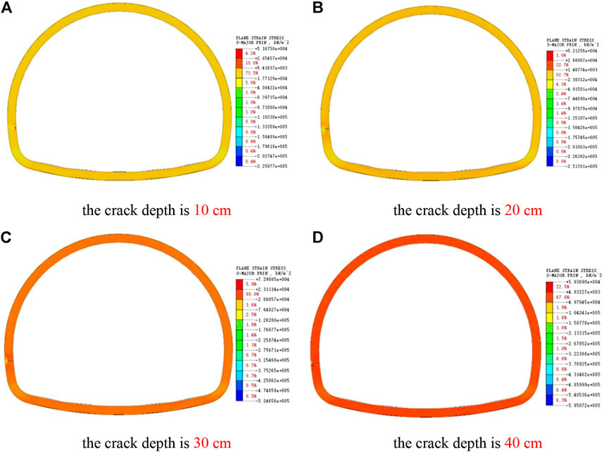
FIGURE 18. Cloud pictures of maximum principal stress of cracks in side walls at different depths. (A) The crack depth is 10 cm. (B) The crack depth is 20 cm. (C) The crack depth is 30 cm. (D) The crack depth is 40 cm.
As shown in Figure 19, with the increase of crack depth, the maximum vertical settlement of lining vault is increasing. Compared with the undamaged lining, the vertical displacement of the inverted arch is increased by the side wall crack, but the change is no longer obvious with the increase of the crack depth.
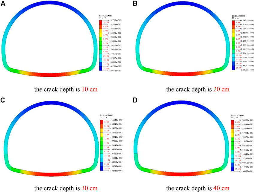
FIGURE 19. Cloud pictures of Y-direction displacement of lining with cracks at different depths of side wall. (A) The crack depth is 10 cm. (B) The crack depth is 20 cm. (C) The crack depth is 30 cm. (D) The crack depth is 40 cm.
In this paper, through numerical analysis of the model of lining cracking at different positions, the influence of lining cracking at different positions on the stress of lining structure and the variation law of displacement are summarized. The main conclusions are as follows:
1) Based on the Yingpanshan tunnel, the numerical analysis shows that the internal force of the deep buried tunnel lining is basically symmetrically distributed without damage, and the internal force will be redistributed after the lining cracks.
2) When the lining cracks, with the increase of the crack width, the stress concentration at the crack of the lining decreases continuously; With the increase of crack depth, the stress concentration at the crack of lining increases continuously. And the stress of other main parts of the lining has increased, which has a certain deterioration effect on the bearing capacity and stability of the lining structure.
3) Cracking of lining has little effect on the lateral deformation of lining, and the small lateral deformation is mainly distributed around the crack. With the increase of crack width and depth, the subsidence deformation of vault and the uplift deformation of inverted arch increase continuously, especially when the crack is wide.
The original contributions presented in the study are included in the article/supplementary material, further inquiries can be directed to the corresponding authors.
Conceptualization: SC and ZY; methodology: SC and ZY; software: SL and LL; validation: YZ and YY; resources: SC and ZY; Data curation: SL and LL; writing—original draft preparation, SL; writing—review and editing: SC and LL; Project administration: SC. All authors have read and agreed to the published version of the manuscript.
This research is sponsored by the Doctoral research start-up fund of Hebei GEO University and Hebei University Youth Fund Project (QN202105) and Key research and development projects in Hebei Province (22371701D) and Hebei Province Innovation Ability Promotion Program (21567628H).
Author ZY was employed by Guangdong Hualu Transport Technology Co., Ltd., China.
The remaining authors declare that the research was conducted in the absence of any commercial or financial relationships that could be construed as a potential conflict of interest.
All claims expressed in this article are solely those of the authors and do not necessarily represent those of their affiliated organizations, or those of the publisher, the editors and the reviewers. Any product that may be evaluated in this article, or claim that may be made by its manufacturer, is not guaranteed or endorsed by the publisher.
Asad, Z., and Majid, A. (2017). Behavior of fiber reinforced concrete for controlling the rate of cracking in canal-lining. Constr. Build. Mat. 155, 726–739. doi:10.1016/j.conbuildmat.2017.08.078
Bai, B., Wang, Y., Rao, D. Y., and Bai, F. (2022). The effective thermal conductivity of unsaturated porous media deduced by pore-scale SPH simulation. Front. Earth Sci. (Lausanne). 10. 943853, doi:10.3389/feart.2022.943853
Bai, B., Yang, G. C., Li, T., and Yang, G. S. (2019). A thermodynamic constitutive model with temperature effect based on particle rearrangement for geomaterials. Mech. Mater. 139, 103180. doi:10.1016/j.mechmat.2019.103180
Bai, B., Zhou, R., Cai, G. Q., Hu, W., and Yang, G. C. (2021a). Coupled thermo-hydro-mechanical mechanism in view of the soil particle rearrangement of granular thermodynamics. Comput. Geotechnics 137 (8), 104272. doi:10.1016/j.compgeo.2021.104272
Bai, X. D., Cheng, W. C., and Li, G. (2021b). A comparative study of different machine learning algorithms in predicting epb shield behaviour: A case study at the xi'an metro, China. Acta Geotech. 16, 4061–4080. doi:10.1007/s11440-021-01383-7
Bai, X. D., Cheng, W. C., Sheil, B. B., and Li, Ge (2021c). Pipejacking clogging detection in soft alluvial deposits using machine learning algorithms. Tunn. Undergr. Space Technol. 113, 103908. doi:10.1016/j.tust.2021.103908
Briffaut, M., Benboudjema, F., and D’Aloia, L. (2016). Effect of fibres on early age cracking of concrete tunnel lining. Part II: Numerical simulations. Tunn. Undergr. Space Technol. 59, 221–229. doi:10.1016/j.tust.2016.08.001
Chen, J. S., and Mo, H. H. (2009). Numerical study on crack problems in segments of shield tunnel using finite element method. Tunn. Undergr. Space Technol. 24, 91–102. doi:10.1016/j.tust.2008.05.007
Fu, L., Zhang, X. M., Wang, L. C., Hou, G. Q., Wei, M., Gao, X., et al. (2021). Discussion on circumferential cracking of tunnel lining based on shrinkage test of machine-made sand concrete. J. Railw. Sci. Eng. 18 (10), 2671–2678. doi:10.19713/j.cnki.43-1423/u.T20210313
Hu, W. L., Cheng, W. C., Wen, S. J., and Rahman, M. M. (2021). Effects of chemical contamination on microscale structural characteristics of intact loess and resultant macroscale mechanical properties. CATENA 203, 105361. doi:10.1016/j.catena.2021.105361
Huang, H. W., Liu, D. J., Xue, Y. D., Wang, P. R., and Liu, Y. (2013). Numerical analysis of cracking of tunnel linings based on extended finite element. Chin. J. Geotechnical Eng. 35, 266–275. Available at: https://kns.cnki.net/kcms/detail/detail.aspx?FileName=YTGC201302012&DbName=CJFQ2013.
Liu, J., Zhang, Q. L., Du, C., and Liu, Z. Y. (2017). Model test of ground penetrating radar detection for high speed railway tunnel lining with defects. China Railw. Sci. 155, 726–739. doi:10.3969/j.issn.1001-4632.2021.05.12
Su, X. K. (2012). Research on choosing boundary range of surrounding rock in numerical simulation of tunnel excavation. J. Railw. Eng. Soc. 29 (03), 64–68. doi:10.3969/j.issn.1006-2106.2012.03.014
Xiao, S. L., Li, K., Jiang, X. H., Wu, S. D., and Yao, C. R. (2021). Study on load-bearing safety and crack evaluation standard of cracked lining. Technol. Highw. Transp. 37 (S1), 41–47. doi:10.13607/j.cnki.gljt.2021.Supp.007
Xu, Z. L., Chen, J. X., Luo, Y. B., Zhu, H. Y., Liu, W. W., Zhou, S., et al. (2022). Geomechanical model test for mechanical properties and cracking features of Large-section tunnel lining under periodic temperature. Tunn. Undergr. Space Technol. 123 (2022), 104319. doi:10.1016/j.tust.2021.104319
Xu, Z. L., Luo, Y. B., Chen, J. X., Su, Z. M., Zhu, T. T., and Yuan, J. P. (2021). Mechanical properties and reasonable proportioning of similar materials in physical model test of tunnel lining cracking. Constr. Build. Mat. 300 (2021), 123960. doi:10.1016/j.conbuildmat.2021.123960
Ye, F., He, C., and Xia, Y. X. (2010). Post-construction monitoring and analysis for highway tunnel lining cracks. China Civ. Eng. J. 43 (07), 97–104. doi:10.15951/j.tmgcxb.2010.07.004
Yuan, T. F. (2019). A research on the impact of the tunnel lining cracking on the structure force performance. Beijing: Beijing Jiaotong University. Doctoral Dissertation, Available at: https://kns.cnki.net/kcms/detail/detail.aspx?dbcode=CMFD&dbname=CMFD202001&filename=1019214697.nh&uniplatform=NZKPT&v=VeAKMzO1MAHgDNBpXyYBzL7fzZ4QXvdVekRqvBpO2EDwfj3k9erj5MUud6UzFGMR.
Zhang, J. H., Song, J. C., and Ma, Z. Y. (2018). Numerical simulation analysis of the excavation methods of deep tunnels under grade-surrounding rock condition. Technol. Dev. Enterp. 37 (11), 5–8. doi:10.14165/j.cnki.hunansci.2018.11.002
Zhang, S. L., Xu, Q., Yoo, C., Min, B., Liu, C., Guan, X. M., et al. (2022c). Lining cracking mechanism of old highway tunnels caused by drainage system deterioration: A case study of liwaiao tunnel, ningbo, China. Eng. Fail. Anal. 137 (2022), 106270. doi:10.1016/j.engfailanal.2022.106270
Zhang, W., Li, X. B., Gong, F. Q., and Li, D. Y. (2007). Cause analysis and numerical simulation study of lining cracking of highway tunnel, Eng. Constr. 2007(01), 26–29. doi:10.3969/j.issn.1673-8993.2007.01.007
Zhang, Z. G., Zhang, M. X., Feng, J., Ma, W. B., Wang, Z. W., and Cheng, Z. X. (2022a). Analyses on structural stability of fiber concrete tunnel lining considering different characteristics of cracks under train loads. Chin. J. Rock Mech. Eng. 41 (S1), 2927–2943. doi:10.13722/j.cnki.jrme.2020.0875
Keywords: road tunnel, lining cracks, numerical simulation, midas-GTS, stress and deformation law
Citation: Chen S, Yang Z, Liu S, Li L, Zheng Y and Yuan Y (2022) Numerical simulation and analysis of crack disease in tunnel lining structure. Front. Mater. 9:1007855. doi: 10.3389/fmats.2022.1007855
Received: 31 July 2022; Accepted: 22 August 2022;
Published: 21 September 2022.
Edited by:
Xianze Cui, China Three Gorges University, ChinaReviewed by:
Jiaqi Guo, Henan Polytechnic University, ChinaCopyright © 2022 Chen, Yang, Liu, Li, Zheng and Yuan. This is an open-access article distributed under the terms of the Creative Commons Attribution License (CC BY). The use, distribution or reproduction in other forums is permitted, provided the original author(s) and the copyright owner(s) are credited and that the original publication in this journal is cited, in accordance with accepted academic practice. No use, distribution or reproduction is permitted which does not comply with these terms.
*Correspondence: Song Chen, Y2hlbm5zb25nZ0AxNjMuY29t; Liufang Li, bGxpdWZ1bkAxMjYuY29t
Disclaimer: All claims expressed in this article are solely those of the authors and do not necessarily represent those of their affiliated organizations, or those of the publisher, the editors and the reviewers. Any product that may be evaluated in this article or claim that may be made by its manufacturer is not guaranteed or endorsed by the publisher.
Research integrity at Frontiers
Learn more about the work of our research integrity team to safeguard the quality of each article we publish.