 Chiara Gazzola
- Department of Civil and Environmental Engineering, Politecnico di Milano, Milan, Italy
Sandwich and composite panels are widely adopted in acoustic applications due to their sound insulation properties that overcome mass-law-based partitions in medium–high frequency regions. A key aspect in the design procedure of acoustic panels is the control of the resonance-dominated region of the sound transmission loss (STL) curve. Within that frequency range, such systems usually show acoustic weakness and poor insulation performances with respect to standard single-layer solutions. In the present contribution, we want to highlight an innovative approach to the sandwich partition concept. A novel single-phase sandwich panel is realized by adopting a periodic repetition of a properly designed unit cell. The resulting internal truss structure is self-sustained, and its mechanical stiffness can be tuned to maximize the STL in the resonance-dominated region. A set of parametric analyses is reported to show how the topology of the unit cell affects the noise reduction properties of the panel. Experimental validation is performed on a nylon 3D-printed prototype. The proposed panel is then integrated with some locally resonant elements that can be adopted to further improve the low-frequency STL of the solution. Industrial and production considerations are also taken into account during the design process to make the solution industrially valid with a circular economy focus.
1 Introduction
The widespread adoption of sandwich-like acoustic panels in many sectors and applications is linked to their significant sound insulation performances combined with low weight and good mechanical strength. Mass–air–mass (MAM) and mass–spring–mass (MSM) systems overcome single-panel noise reduction performances over a wide frequency range. Multi-layered partitions are, however, characterized by a mass–spring–mass resonance, where clear weakness in terms of acoustic performances arises. For this reason, such frequency ranges must be considered and rigorously analyzed during the design process. This resonance is strictly related to the stiffness of the multi-layered panel, which is determined by the geometry and material composition of the latter (Isaac et al., 2020; Zarastvand et al., 2021).
Different kinds of cores for such panels have been investigated in the recent literature, including air cavities, porous or fibrous materials, honeycomb, truss, or lattice structures. Honeycomb sandwiches are usually adopted in applications where high stiffness, good shock resistance, and low mass are required. However, the latter features usually lead to an increase in noise transmission through the structure (Radestock et al., 2019). Sandwich panels with truss-core demonstrate interesting dynamic, acoustic, and mechanical properties that strongly depend on the core configuration (e.g., pyramids, tetrahedrons, and hourglass) (Wen-Chao and Chung-Fai, 1998; Wang and Ma, 2017; Qing and Deqing, 2018; Guo et al., 2021; Wen et al., 2021).
The design process of the panel's internal core is still a point of intense research (Spadoni and Ruzzene, 2006; Shen et al., 2013; Quinteros et al., 2021). The main issue remains related to finding an effective compromise between sound insulation performances and the mechanical strength of the panel.
The aim of the present contribution is to propose a new sandwich panel concept with an engineered shape that match significant noise reduction performances and a structure with self-standing properties. The proposed innovative core is a modification of the one proposed by Gazzola et al. (2021). It has been designed from the acoustic point of view to not overstiffen the panel and leave to the airgap the main stiffness contribution that defines the system resonance.
A series of parametric analyses have been carried out to optimize the acoustic performances of the sandwich panel in the resonance-dominated region and to define the more promising configuration in terms of internal beam dimensions and the presence of holes dug on the massive elements of the unit cell.
An additional aim of this work is to show further developments that can be implemented to improve the low-frequency performances of the proposed panel with a metamaterial-based approach, coupling its core with locally resonant elements, similar to the strategy proposed by Lin et al. (2016), de Melo Filho et al. (2019a, b) de Melo Filho et al. (2020). Inclusions that act as locally resonant elements are introduced in the panel core, increasing the STL response in the 200–250 Hz region.
Another point taken into account in the design process is the industrialization of the panel through a circular economy approach. The panel core is conceived as a single-phase structure, which can be entirely produced through the injection molding technique. This makes possible the realization of an acoustic insulating solution entirely made in regenerated plastic material.
The study is structured as follows: the panel unit cell geometry and the numerical design approach are described in Section 2. Results of numerical simulations and parametric analyses are reported in Section 3 as well as the analytical lumped mass model to predict the MSM resonance frequency. In Section 4, experimental results and validation of performances of the final selected design on a 3D-printed panel are presented. In Section 5, a metamaterial approach for the panel is introduced from the numerical point of view. The proposed solution, i.e., the introduction of local resonators embedded in the unit cell, can be implemented to improve the STL response of the partition in critical parts of the spectrum at low frequencies. Finally, in Section 6, conclusions are drawn.
2 Materials and methods
In this section, a detailed description of the acoustic panel unit cell is presented along with the numerical tools exploited for the SPL estimation.
2.1 Acoustic panel geometry
The acoustic panel core is composed of a periodic structure with an in-plane repetition of a primitive cell.
The unit cell geometry is a modification of the one proposed by Gazzola et al. (2021). The latter was composed of six massive pyramidal elements connected by a 3D frame and it was designed according to the principle of separation of modes (D’Alessandro et al., 2017) to obtain an ultrawide-band gap at low frequencies (Figure 1). This ensured that the mechanical modes of the core do not interfere with the acoustic transmission loss performances of the panel. The lumped-parameter model proposed for this configuration showed the needed modifications in the geometry of the unit cell to optimize the STL performance at low frequencies. In particular, it was shown that the massive elements can be redistributed to maximize the lateral mass of the unit cell and minimize the internal one, which does not contribute to the modal mass of the MSM resonance mode. Moreover, the frame stiffness can be further reduced in order to make the mechanical stiffness negligible with respect to the air stiffness. These considerations have been taken into account to propose the innovative unit cell of this contribution.
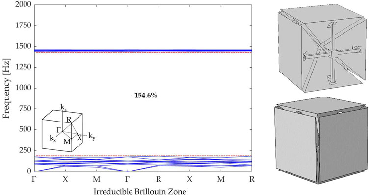
FIGURE 1. Dispersion diagram of the unit cell proposed in (Gazzola et al., 2021) with a schematic of the investigated irreducible Brillouin zone. The red dotted lines identify the opening and closing frequencies of the first band gap, respectively, fo = 184 Hz and fc = 1437 Hz. The gap-to-mid-gap ratio is also reported.
The unit cell analyzed here consists of two massive elements (Figure 2A) connected by four elastic ligaments placed on a cross-shaped frame that give structural stiffness to the panel (Figure 2B). The aforementioned internal core is then integrated with a couple of 3.0 mm thick planar elements to create the final acoustic partition (Figures 2C,D).
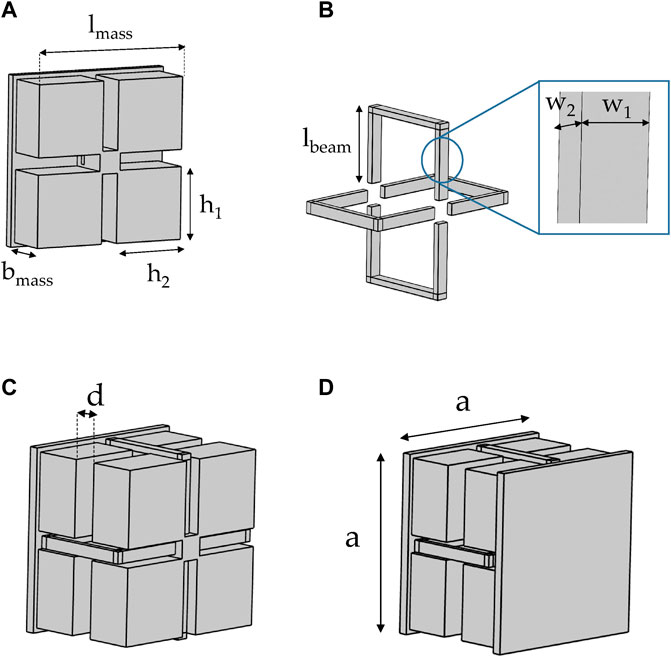
FIGURE 2. Unit cell geometry: (A) massive elements connected by (B) four ligaments placed on a cross-shaped frame. (C) Masses and internal frame assembly and (D) complete external view of the unit cell, 60 × 60 × 46 mm.
The working principle of the beam elements has been designed to integrate the geometry proposed by Gazzola et al. (2021) with industrial and production considerations for plastic injection molding. The flexural behavior of the ligaments, from the dynamic and acoustic point of view, allows playing with an additional degree of freedom in the panel mechanical stiffness definition. At the same time, the panel can be conceived as a monolithic sandwich structure with both massive and ligament elements made of the same material; thus, obtaining a suitable configuration for plastic molding manufacturing.
This type of production approach brings some additional constraints in the definition of the geometry of the unit cell, e.g., undercuts must be avoided and holes are needed in the massive elements to facilitate the cooling process after the molding of the plastic. The unit cell has global dimensions of 60 × 60 × 46 mm. The fundamental geometrical features of the cell are highlighted in Figure 2. In particular, lmass = 0.057 m, bmass = 0.016 m, h1 = h2 = 0.0255 m, lbeam = 0.026 m, w1 = 0.004 m, w2 = 0.002 m, d = 0.008 m, and a = 0.060 m. The material adopted for the prototype and for all the numerical simulations reported in what follows is nylon PA12, characterized by Young’s modulus E = 1.586 GPa, Poisson’s ratio ν = 0.4, volumetric mass density ρ = 1000 kg/m3, and loss factor η = 0.05. This led to an overall partition mass of 26 kg/m2.
2.2 Acoustic panel modeling
The sound transmission loss (STL) of the proposed solution is determined numerically by adopting a FEM plane wave model (Langfeldt and Gleine, 2019) implemented in COMSOL Multiphysics v5.6, by coupling the pressure acoustics and structural mechanics modules. As shown in Figure 3A, a primitive cell is modeled and the performances of the entire panel are reproduced due to the application of the Bloch−Floquet boundary conditions, both at the lateral boundaries of the unit cell (see Figure 3B) and at the air domain along the tube.
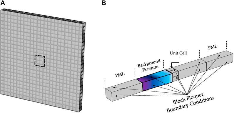
FIGURE 3. (A) Complete acoustic panel view and identification of the modeled unit cell. (B) The plane-wave FEM model for sound transmission loss calculation.
Perfectly matched layers (PMLs) are placed on the tube terminations.
The calculation of STL is computed as follows:
with Pin and Pout representing the sound pressure computed at two sections before and after the sound insulation module. A normal incidence pressure wave model (without structural damping) is adopted for the simulations reported in Section 3. In that section, a lumped mass analytical model is presented with the aim of predicting low-frequency resonances by means of a simplified tool. In Section 4, instead, the numerical STL is computed with a complete FEM model that takes into account both diffuse incidence equations and panel finite size correction, in order to have the best agreement between numerical and experimental data. The complete model formulation here is summarized as follows:
where T(θ) is the transmission coefficient, θlim = 90 deg, and σR,avg is the averaged geometrical efficiency with its dependency on the incidence angle. A total of eight frequencies in each 1/3 octave band and twenty incidence angles between 0 and 90 degrees are considered. A standard linear viscoelastic behavior is adopted in the FEM model whose results are reported in Section 4. The complete formulation of the constitutive law can be found in previous works (D’Alessandro et al., 2016, 2019), while further details about the numerical formulation are reported by Bonfiglio et al. (2016) and Gazzola et al. (2021).
3 Numerical results
In the following, a set of parametric studies is presented, to show the panel acoustic performances at varying geometrical features of the unit cell. In particular, the effects in terms of STL modifying the geometric dimensions of the elastic frame (Section 3.1) and the number and position of holes in the massive element (Section 3.2) are presented. These studies allow us to select the most effective unit cell configuration, which is then exploited to build the prototype for experimental validation. To limit the computational burden, these preliminary simulations are performed adopting a normal incidence model setting θ = 0 in the formulation reported in Section 2.2.
3.1 Geometric dimensions of the elastic ligament
One of the main geometrical features that characterize acoustic partition performances is the beam elements dimension. The STL curves by varying the ligaments dimension w2 (Figure 2B) in the range 2.0–4.0 mm are reported in Figure 4. The effect of reducing the thickness of the beam is a progressive shift at a low frequency of the MSM resonance. For w2 = 2.0 mm the latter occurs at 187 Hz. At medium-high frequency (between 500 Hz and 2000 Hz), the analysis of the ligaments dimension shows a variation of the second resonance frequency that arises due to the frame flexural mode as shown in Figure 5. From the graph presented in Figure 4 the green STL curve (w1 = 4.0 mm and w2 = 2.0 mm) is selected to proceed with further analysis of the panel geometry.
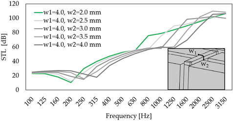
FIGURE 4. Sound transmission loss of the panel in 1/3 octave bands at varying beam dimensions.
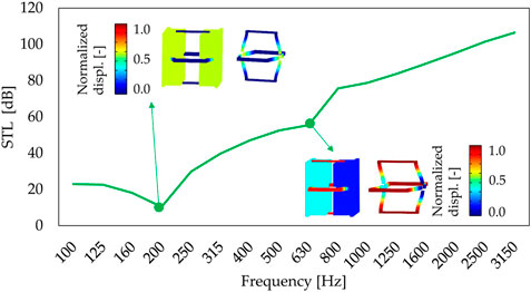
FIGURE 5. Sound transmission loss of the panel in 1/3 octave bands considering w1 = 4.0 mm and w2 = 2.0 mm with a focus on the mass–spring–mass resonance occurring at 187 Hz and beam elements mode at 630 Hz.
3.2 Number and positions of holes
As mentioned in Section 2.1, the geometry of the panel is designed considering the adoption of injection printable recycled materials. For this purpose, the massive elements that compose the panel core need to be holed to facilitate mass production with recycled plastic molding. This technique is adopted in the mold design phase to avoid strong temperature gradients that can lead to permanent deformations on the finite plastic component. The geometry of the panel is hence modified as depicted in Figure 6, considering three different configurations of holes for which the printing time is comparable. In the proposed holed configurations the thickness of the massive elements is adjusted to preserve the core mass of the unholed configuration. In all three configurations, the air volume enclosed in the holes is the same to maintain constant stiffness contribution related to the air inside the partition. This will be better highlighted in Section 3.3.
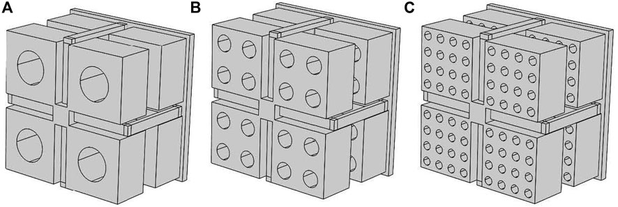
FIGURE 6. Different holes configuration analyzed: (A) four holes configuration, (B) sixteen holes configuration, and (C) sixty-four holes configuration.
Due to the equivalence in mass and stiffness, the STL curves for the three-holed configurations are superimposed (Figure 7). The sixty-four-hole configuration is the one selected for the experimental validation due to a better void distribution on the surfaces of the massive elements.
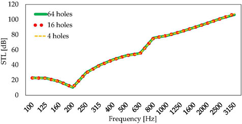
FIGURE 7. Sound transmission loss of the proposed acoustic partition in 1/3 octave bands at varying hole positions and dimensions.
3.3 Lumped-parameter model
The mass–spring–mass resonance frequency which appears at 187 Hz (Figure 5) can be described by the lumped-parameter model reported in Figure 8A following the procedure presented by Gazzola et al. (2021). At this resonance, the faceplates and the massive elements (m1 = m2 = 0.0042 kg) vibrate at the stiffness of the system, given by the air enclosed in the panel (ka) and by the elastic ligament (km). The corresponding deformed shapes are reported in Figure 8B for the lumped model and in Figure 8C for the FEM model.
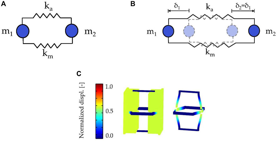
FIGURE 8. (A) Lumped-parameter model and (B) deformed shape corresponding to the mass–spring–mass resonance at 187 Hz of the lumped model and (C) of the FEM model.
The air stiffness ka is computed as BAp/deq = 24,640 N/m. B = ρ0c2 represents the adiabatic bulk modulus of air, ρ0 = 1.225 kg/m3 and c = 340 m/s is the air density and the speed of sound considered, respectively. Ap = 0.0036 m2 is the surface area of the unit cell and its equivalent thickness deq = 20.7 mm is derived by computing the air volume enclosed in one unit cell (Va = 7.4484 ⋅ 10–5 m3) and dividing it by the single unit cell surface (Ap).
The eight L-shaped beams of the elastic frame determine the panel's structural stiffness. In particular, the bending stiffness of the aforementioned ligaments is calculated considering a clamped−clamped beam scheme, whose bending stiffness reads km,1B = 12EI/l3 = 3248N/m, with
The mechanical stiffness of the four beams forming one-half of the frame is equal to kg = 4 ⋅ km 1B = 12,993 N/m. Hence, the stiffness of the whole elastic structure is equal to km = kg/2 = 6496 N/m, being the two grids in a series configuration.
According to D’Alambert’s principle, the lumped mass systems equation of motion is set as follows:
The harmonic motion hypothesis is considered to introduce x = Xeiωt to solve the linear eigenvalue problem. The MSM resonance predicted by the lumped model is equal to 189 Hz (+1% with respect to the FEM prediction).
The same frequency can be predicted starting from the MAM formula for a standard double-leaf partition, which reads as follows (Norton and Karczub, 2010; de Melo Filho et al., 2019a):
where
with mi the mass of the i-th wall leaf. For the panel under investigation, there is also the stiffness contribution of the elastic frame, the MSM resonance can then be determined as follows:
It is worth mentioning that mechanical stiffness represents only 20% of the total stiffness.
4 Experimental results
In this section, the final comparison between the tested 3D-printed prototype and the complete numerical analysis of the panel is shown. The numerical STL curve is determined through the complete diffuse field FEM model presented in Section 2.2 considering θ varying through twenty incidence angles between 0 and 90° and eight frequencies for a 1/3 octave band.
The experimental acoustic sound insulation of the panel is determined through a measurements campaign on a 3D-printed prototype in nylon PA12. The panel consists of 12 × 12 × 1 unit cells that result in a total dimension of 800 × 800 × 46 mm. A unit cell detailed view is depicted in Figure 9C. Due to SLS 3D printing technology, the whole unit cell is printed together (front panel, back panel, and core) avoiding the assembly procedure.
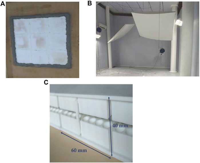
FIGURE 9. (A) Acoustic panel mounted and sealed on the test window, (B) reverberant room view, and (C) prototype unit cell detail.
The panel prototype has been characterized in a coupled chambers laboratory (Figure 9B) and STL has been determined. Mastic sealing was arranged on the panel boundaries during the installation on the window between the reverberant and the hemi-anechoic chamber (see Figure 9A). The total volume of the reverberant room is 252 m3 and a tetrahedral source of the type Genelec 8351A is adopted. A total of six microphones B&K 1/4” type 4135 for sound pressure measurements in the source room are exploited, while the sound power in the receiving room is measured by means of a B&K sound intensity PP probe type 2681. The good agreement reached between the experimental test and the complete diffuse field model is shown in Figure 10.
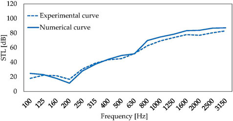
FIGURE 10. Comparison between the numerical STL curve determined through the diffuse field FEM model and experimental STL curve performed in the double-chamber lab.
5 Metasolution and locally resonant elements
The purpose of this section is to give an idea of the potentiality that a single-phase sandwich partition can obtain in terms of transmission loss improvement if coupled with the metamaterial concept of locally resonant inclusions.
As mentioned in Section 1, MSM panels show performances that exceed the sound insulation power of a common mass-law-based partition, especially in the medium−high frequency range. The resonance of the MSM system, however, results in a dip, in this case set to 187 Hz (Figure 5), where the STL has its minimum value. For this reason, effective solutions based on locally resonant metamaterials principle to improve sandwich panels insulation at their resonance frequency are extensively present in the recent literature (Lin et al., 2016; de Melo Filho et al., 2019a,b, 2020).
Coherently with the design process followed in the previous sections, a resonant element design embedded in the partition geometry is proposed. The massive elements that compose the panel core can be modified to maintain the injection moldable configuration, which is a key aspect of industrial production. The hosted resonant elements are, hence, designed by tuning their own frequency with the one of the MSM system.
Resonators are composed of a beam element, linked to the main body of the unit cell and a cylindrical massive part (Figures 11A,B). The following dimensions are adopted: dmass = 0.014 m, hmass = 0.014 m, lbeam = 0.003 m, hbeam = 0.0015 m, and wbeam = 0.003 m (see Figure 11C). The overall mass of the partition has been maintained at 26 kg/m2 with the resonator's mass set to 5 kg/m2 (mres/Mtot = 19%).
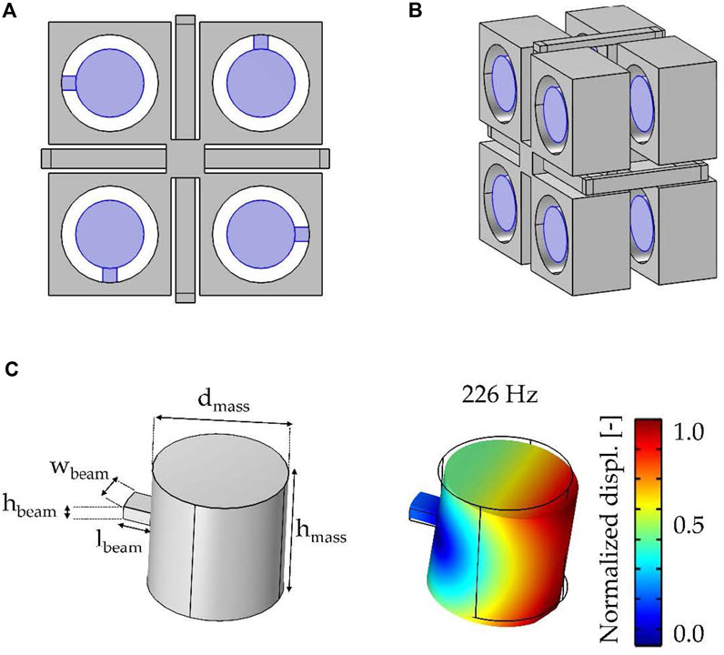
FIGURE 11. Unit cell view of the locally resonant hosting configuration. (A) Front view, (B) lateral view, and (C) resonator geometry detail and the first flexural eigenmode.
Figure 12 highlights the improvement in correspondence of the MSM dip of the baseline system due to the introduction of the locally resonant element. The STL dips before and after the peak are due to the creation of two new mass–spring–mass resonances in the metamaterial double panel, as highlighted by de Melo Filho et al. (2019a, 2020). Hence, the proposed metasolution provides a narrow-band STL improvement through a tunable STL peak, at the expense of the two dips.
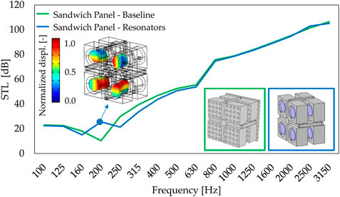
FIGURE 12. Normal incidence transmission loss comparison in 1/3 octave bands between the baseline configuration and resonator hosting configuration.
In the recent literature, different strategies were proposed to broaden the attenuation frequency range. Van Belle et al. (2019) showed that the increase in the damping of the resonator can improve the STL dips; however, it also reduces the STL peak performance. Janssen et al. (2021); Hall et al. (2020, 2021) demonstrated that an effective approach to reduce the insulation dips, while preserving the peak performance, is to exploit a set of different resonators with closely spaced resonance frequencies. These design strategies will be taken into account for the future optimization of the metapartition.
6 Conclusion
The present contribution describes in detail the study, design, fabrication, and experimental performances of an innovative acoustic sandwich panel. The peculiarity of the proposed geometry is the internal core, an in-plane repetition of multiple engineered unit cells, coupled with two closing plane panels. The unit cell is composed of two principal massive elements supported by a frame of beams.
Such a panel core is numerically and experimentally analyzed to give the partition a self-sustaining capability and optimized sound insulation performances. In particular, the frame has been designed from the acoustic point of view to not overstiffen the panel and leave to the airgap the main stiffness contribution that defines the system MSM resonance, which is accurately predicted by the lumped-parameter model proposed.
During the entire design process, considerations about solution production via plastic injection molding have been taken into account. The acoustic transmission loss performances are validated by an experimental campaign on a 3D-printed nylon prototype, showing a good agreement between the proposed numerical impedance tube model and the sound insulation measured in the double chamber lab.
The last section introduces a further step in the optimization process of the panel explaining how the unit cell can be easily coupled with properly tuned locally resonant elements to improve the low-frequency STL in correspondence with the MSM resonance. A more detailed investigation of this metasolution, including the experimental verification that for this unit cell configuration the residual stresses induced by the cooling process do not affect the acoustic performances of the panel, will be the object of future work.
Data availability statement
The raw data supporting the conclusion of this article will be made available by the authors, without undue reservation.
Author contributions
Conceptualization, methodology, and validation: CG and SC; writing—original draft preparation and figures preparation: CG and SC; writing—review and editing: SC, CG, and AC; supervision: AC; and funding acquisition: AC. All authors have read and agreed to the published version of the manuscript.
Funding
The authors acknowledge the contribution of Fondazione Cariplo. The research was carried out within the framework of Project “2018-1743 META-matErials as new teChnOlogy for high performing acoustic InSulatiOn paneLs, made of end of life MATerials.”
Acknowledgments
The authors would like to thank Materiacustica S.r.l. and Paolo Bonfiglio for their precious support during the experimental tests.
Conflict of interest
The authors declare that the research was conducted in the absence of any commercial or financial relationships that could be construed as a potential conflict of interest.
Publisher’s note
All claims expressed in this article are solely those of the authors and do not necessarily represent those of their affiliated organizations, or those of the publisher, the editors, and the reviewers. Any product that may be evaluated in this article, or claim that may be made by its manufacturer, is not guaranteed or endorsed by the publisher.
References
Bonfiglio, P., Pompoli, F., and Lionti, R. (2016). A reduced-order integral formulation to account for the finite size effect of isotropic square panels using the transfer matrix method. J. Acoust. Soc. Am. 139, 1773–1783. doi:10.1121/1.4945717
D’Alessandro, L., Ardito, R., Braghin, F., and Corigliano, A. (2019). Low frequency 3d ultra-wide vibration attenuation via elastic metamaterial. Sci. Rep. 9, 8039. doi:10.1038/s41598-019-44507-6
D’Alessandro, L., Belloni, E., Ardito, R., Braghin, F., and Corigliano, A. (2017). Mechanical low-frequency filter via modes separation in 3d periodic structures. Appl. Phys. Lett. 111, 231902. doi:10.1063/1.4995554
D’Alessandro, L., Belloni, E., Ardito, R., Corigliano, A., and Braghin, F. (2016). Modeling and experimental verification of an ultra-wide bandgap in 3d phononic crystal. Appl. Phys. Lett. 109, 221907. doi:10.1063/1.4971290
de Melo Filho, N., Belle, L. V., Claeys, C., Deckers, E., and Desmet, W. (2019a). Dynamic mass based sound transmission loss prediction of vibro-acoustic metamaterial double panels applied to the mass-air-mass resonance. J. Sound Vib. 442, 28–44. doi:10.1016/j.jsv.2018.10.047
de Melo Filho, N., Claeys, C., Deckers, E., and Desmet, W. (2020). Metamaterial foam core sandwich panel designed to attenuate the mass-spring-mass resonance sound transmission loss dip. Mech. Syst. Signal Process. 139, 106624. doi:10.1016/j.ymssp.2020.106624
de Melo Filho, N., Claeys, C., Deckers, E., and Desmet, W. (2019b). Realisation of a thermoformed vibro-acoustic metamaterial for increased stl in acoustic resonance driven environments. Appl. Acoust. 156, 78–82. doi:10.1016/j.apacoust.2019.07.007
Gazzola, C., Caverni, S., and Corigliano, A. (2021). From mechanics to acoustics: Critical assessment of a robust metamaterial for acoustic insulation application. Appl. Acoust. 183, 108311. doi:10.1016/j.apacoust.2021.108311
Guo, Z., Hu, G., Sorokin, V., Yang, Y., and Tang, L. (2021). Sound transmission through sandwich plate with hourglass lattice truss core. Jnl. Sandw. Struct. Mater. 23 (6), 1902–1928. doi:10.1177/1099636220906819
Hall, A. J., Dodd, G., and Calius, E. P. (2020). Multiplying resonances for attenuation in mechanical metamaterials: Part 1 – concepts, initial validation and single layer structures. Appl. Acoust. 170, 107513. doi:10.1016/j.apacoust.2020.107513
Hall, A. J., Dodd, G., and Calius, E. P. (2021). Multiplying resonances for attenuation in mechanical metamaterials: Part 2 - multi-layer structures. Appl. Acoust. 179, 108041. doi:10.1016/j.apacoust.2021.108041
Isaac, C. W., Pawelczyk, M., and Wrona, S. (2020). Comparative study of sound transmission losses of sandwich composite double panel walls. Appl. Sci. 10, 1543. doi:10.3390/app10041543
Janssen, S., Van Belle, L., Rocha de Melo Filho, N. G., Claeys, C., Desmet, W., and Deckers, E. (2021). Improving the noise insulation performance of vibro-acoustic metamaterial panels through multi-resonant design. DSTA-2021 Conference Books – Abstracts.
Langfeldt, F., and Gleine, W. (2019). Membrane- and plate-type acoustic metamaterials with elastic unit cell edges. J. Sound Vib. 453, 65–86. doi:10.1016/j.jsv.2019.04.018
Lin, Q., Lin, Q., Wang, Y., and Di, G. (2016). Sound insulation performance of sandwich structure compounded with a resonant acoustic metamaterial. Compos. Struct. 273, 114312. doi:10.1016/j.compstruct.2021.114312
Norton, M. P., and Karczub, D. G. (2010). Fundamentals of noise and vibration analysis for engineers. Cambridge University Press.
Qing, L., and Deqing, Y. (2018). Mechanical and acoustic performance of sandwich panels with hybrid cellular cores. J. Vib. Acoust. 140. doi:10.1115/1.4040514
Quinteros, L., Meruane, V., Cardoso, E. L., and Ruiz, R. O. (2021). Phononic bandgap optimization in sandwich panels using cellular truss cores. Materials 14, 5236. doi:10.3390/ma14185236
Radestock, M., Haase, T., and Monner, P. H. (2019). Experimental transmission loss investigation of sandwich panels with different honeycomb core geometries.Internoise.
Shen, C., Xin, F., Cheng, L., and Lu, T. (2013). Sound radiation of orthogonally stiffened laminated composite plates under airborne and structure borne excitations. Compos. Sci. Technol. 84, 51–57. doi:10.1016/j.compscitech.2013.05.006
Spadoni, A., and Ruzzene, M. (2006). Structural and acoustic behavior of chiral truss-core beams. J. Vib. Acoust. 128, 616–626. doi:10.1115/1.2202161
Van Belle, L., Claeys, C., Deckers, E., and Desmet, W. (2019). The impact of damping on the sound transmission loss of locally resonant metamaterial plates. J. Sound Vib. 461, 114909. doi:10.1016/j.jsv.2019.114909
Wang, D., and Ma, L. (2017). Sound transmission through composite sandwich plate with pyramidal truss cores. Compos. Struct. 164, 104–117. doi:10.1016/j.compstruct.2016.11.088
Wen, Z., Wang, D., and Ma, L. (2021). Sound transmission loss of sandwich panel with closed octahedral core. Jnl. Sandw. Struct. Mater. 23 (1), 174–193. doi:10.1177/1099636219829369
Wen-Chao, H., and Chung-Fai, N. (1998). Sound insulation improvement using honeycomb sandwich panels. Appl. Acoust. 53, 163–177. doi:10.1016/S0003-682X(97)00033-9
Keywords: sandwich panel, periodic panels, sound transmission loss, circular economy, locally resonant material
Citation: Gazzola C, Caverni S and Corigliano A (2022) Design and modeling of a periodic single-phase sandwich panel for acoustic insulation applications. Front. Mater. 9:1005615. doi: 10.3389/fmats.2022.1005615
Received: 28 July 2022; Accepted: 20 October 2022;
Published: 08 November 2022.
Edited by:
Nicola Maria Pugno, University of Trento, ItalyReviewed by:
Gianluca Rizzi, Technical University Dortmund, GermanyAnastasiia O. Krushynska, University of Groningen, Netherlands
Copyright © 2022 Gazzola, Caverni and Corigliano. This is an open-access article distributed under the terms of the Creative Commons Attribution License (CC BY). The use, distribution or reproduction in other forums is permitted, provided the original author(s) and the copyright owner(s) are credited and that the original publication in this journal is cited, in accordance with accepted academic practice. No use, distribution or reproduction is permitted which does not comply with these terms.
*Correspondence: Alberto Corigliano, alberto.corigliano@polimi.it