 Hafiz Muhammad Waqas
 Dongyan Shi1*‡
- 1College of Mechanical and Electrical Engineering, Harbin Engineering University, Harbin, China
- 2Department of Mechanical Engineering, Faculty of Engineering, Islamic University of Madinah, Madinah, Saudi Arabia
- 3Department of Mechanical Engineering, Faculty of Engineering, Taif University, Taif, Saudi Arabia
- 4Production and Mechanical Design Department, Faculty of Engineering, Mansoura University, Mansoura, Egypt
- 5Civil Engineering Department, Military Technical College, Cairo, Egypt
- 6Ships and Submarines Engineering Department, Military Technical College, Cairo, Egypt
The main objective of this study is to design composite shells i.e. long, short, thin and thick for the different underwater applications. These shells can be a part of pressure hulls, underwater vehicles, pressurized tanks, underwater cables and underwater pipelines etc. This paper presents comprehensive procedures for the mathematical modeling of elastic buckling for submersible composite shells under hydrostatic pressure. First order shear deformation theory (FOSDT) was used for modeling. FOSDT theory was mathematically derived under hydrostatic pressure for composite shells, and it can be used for all types of submersible shells. After the derivation of the theory, mathematical code was formed on MATLAB for this modeling. From the given formulation one can design the shell structure according to his needs on different environment conditions. Different types of composite shells, including moderately thick, thick, long, and short, are investigated for the FOSDT formulation to check the accuracy range. The results were compared with previous studies and finite element analysis FEA. Three types of materials, Carbon/Epoxy, Glass/Epoxy, and Boron/Epoxy, were used with different cross-ply symmetric and unsymmetrical angle configurations. The layups used for the analysis were [0/90/0]s [90/0/90/0]s [02/902]s [90/02/90]s [0/902/0]s [0/0/0/90]s [90/90/90/0]s and [0/90].
1 Introduction
The composite shells laminated with plies are the most important composite structures which are used in the marine industry as submersible pressure hulls (Shakeri et al., 2005; Fathallah et al., 2014a; Shen et al., 2018; Shaker et al., 2021) radomes, fuel tanks, and fuselages in the aerospace industry (Almeida et al., 2017; Almeida et al., 2019). Buckling is the main failure that occurs when an external loading is applied on these shells, which causes geometric deformation or collapse of the structure. To design these types of shells, buckling instability is considered a main factor influenced by the different levels of depths. Many theories and experimental approaches have been studied earlier to determine the buckling instability of composite shells. Alexey Semenov (Semenov, 2021) studied the buckling of the shell panels which were made up of fiberglass and reinforced with stiffeners. Timoshenko type mathematical model was used for the analysis. Cho-Chung Liang (Liang et al., 2003) worked on multi-layer filament wound sandwich submersible shells and studied the buckling of the shells by using Shell Buckling Equation SBE. Effects of transverse shear stress and pressure stiffness were not considered while using SBE. Chul-Jin Moon (Moon et al., 2010) conducted experiments and FEA on composite cylindrical shell under hydrostatic pressure. It was concluded that the cylindrical shell structure did not come back to its initial position after the initial buckling.
Classical Shell Theory CST, first-order shear deformation theory FOSDT and Higher order shear deformation theories HOSDT are extensively used for mathematical modeling to calculate the buckling factor. The main difference between these three theories is that in FOSDT, and HOSDT transverse shear stress is considered, but it is not considered in CST. Some of the literature work done on the submersible composite shells is mentioned here. Loptain and Morozov (Lopatin and Morozov, 2012) studied cantilever circular shells and gave a procedure for applying orthotropic and isometric cylindrical shells under different loading conditions. They used CST to develop their mathematical model, and the Garlinin method was used for the solution. FEA was done to validate the analytical model. Loptain and Morozov (Lopatin and Morozov, 2017) also changed the boundary conditions to rigid ends and developed the model of a cylindrical shell under hydrostatic pressure. Galerkin’s and Fourier Decomposition methods were used to study the CST-based mathematical model. The third derivative of the beam function was used to calculate the axial displacement of the shell. Its hoop displacement and deflection were also modeled in their respective studies. Cagdas and Adali (Cagdas and Adali, 2011) also worked on buckling of the cross-ply laminated cylindrical shells under hydrostatic pressure. Pressure stiffness was also accounted in their FOSDT-based model, and they applied Koiter’s related energy while employing pressure stiffness. Buckling analysis was done after the validation of a mathematical model for the GFRP and CFRP composite cylinders. Golden Section Method was also used in their studies to find an optimal design for the cylindrical shells under hydrostatic pressure. They also studied how different parameters affect the optimal design of the composite cylindrical shell. Ebrahimi et al. (Ebrahimi et al., 2020) introduced the Nanocomposites in composite shells. He studied the graphene oxide powder cylindrical shells and their buckling analysis on the basis of FOSDT. The principle of virtual work was used to develop the mathematical model of the shell. They used Galerkin’s method to derive the stability equations. Circumferential wave numbers were changed to get the new values of buckling pressure. The mathematical model was verified by the previous results found in the literature. Sofiyev and Kuruoglu (Sofiyev and Kuruoglu, 2014) studied the theory of shear deformation on the basis of the Donnel shell theory to find the vibration and buckling of the cylindrical composite shells for the hydrostatic pressure. To find the buckling pressure and frequency of the shell, parametric analysis was done, and its influence on the different parameters was examined. Imran et al. (Imran et al., 2021b) worked on the analytical modeling of cross-ply composite laminated submersible shells with closed ends under hydrostatic pressure with the help of CST and FOSDT. Two types of composite materials, carbon/epoxy, and glass/epoxy, were used in the modeling of shells. Umut Topal (Topal, 2009) used FOSDT to develop a new methodology based on FEA for the optimum design of a thin cylindrical shell composed of composite material under external load. Cadges (Cagdas, 2011) used FOSDT to carry out elastic buckling analysis of cross-ply laminated shells of revolution under compressive loads. The linear stability analysis was done by him. A comparison was made between the analytical and numerical results found in the literature. Moreover, for the calculation of buckling load, a linear buckling analysis has been done to find the optimal solution for submersible shells. FOSDT was used to develop the shell element in these studies (Fathallah et al., 2014a; Fathallah et al., 2014b; Fathallah et al., 2015; Imran et al., 2019; Waqas et al., 2019; Imran et al., 2021a).
Applications of these composite shell structures are present in almost every field. Submersible pressure hulls are one of the most significant applications in marine field. Composite shells are the main structural parts of composite pressure hulls (Craven et al., 2013; Fathallah et al., 2014a; Fathallah, 2019; Imran et al., 2019; Imran et al., 2021a). Another application of this composite shell is in submarine radome (Waqas et al., 2019). One of the other marine applications of composite shells is in underwater pipelines (Lam et al., 2003; Davoud and Rahimi, 2019; Venhrynyuk et al., 2021). Composite shells are also used in LPG Liquefied Petroleum Gas Carriers and pressurized tanks (Alarçin and Alarcin, 2015).
Literature review shows that the topic of composite cylindrical shells is critical, and researchers have great interest in it, and much work has been done. The significant thought in the buckling examination of the composite shell is the consideration of pressure stiffness. The pressure stiffness incredibly influences the buckling instability of the submersible composite shell. In order to effectively predict the composite shell’s buckling behavior, it is essential to apply the pressure load in accordance with the real implementation of the composite shell. Based on the FOSDT and taking pressure stiffness into account, the mathematical formulation for the submersible composite cylindrical shell under hydrostatic pressure is developed. The results were compared with the previous literature. The main objective of this study is to design composite shells i.e. long, short, thin and thick for the different underwater applications. These shells can be a part of pressure hulls, underwater vehicles, pressurized tanks, underwater cables and underwater pipelines etc. From the given formulation one can design the shell structure according to his needs on different environment conditions. In this work, the previous work was verified, and results with new configurations are discussed in detail. Finite element analysis using shell elements is also carried out in ANSYS to verify the analytical model.
2 Mathematical modeling of thin composite cylindrical shell using FOSDT
2.1 Geometry and coordinates of plies of submersible shell
Here the mechanical characteristics of the shell under hydrostatic pressure were analyzed by using FOSDT. All the modeling is presented on the basis of the coordinate system shown in Figure 1. This is cross-ply shell, and the composite plies are on 0 and 90° angles as shown in the Figure 1. h is the total thickness, and l is the total length of the shell. P shows the external hydrostatic pressure applied. R is the radius, and α is the angle between the radius and the z-axis of the coordinate system.
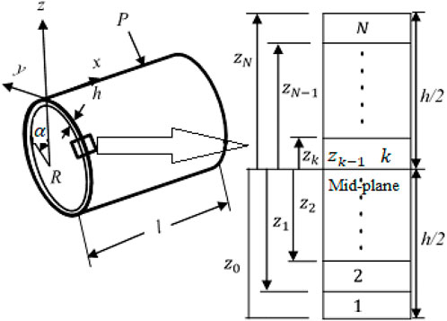
FIGURE 1. Geometry and coordinates of plies of submersible shell.
FIGURE 2. Schematic diagram of the problem.
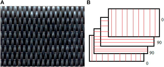
FIGURE 3. Sample of plies (A) Carbon/Epoxy 0° (B) Sample of [0/902/0] configuration.
Following assumptions are made for our model.
• Hydrostatic pressure is acting normal on the surface of the shell.
• The orientations for the fiber plies are considered [0/90] degrees.
• The effect of imperfections was not considered, and the perfect structure was assumed.
• The value of the product of correction factors was assumed 5/6.
• The value of
2.2 Kinematic and forces and moments resultants equations
In this section, buckling formulation under hydrostatic pressure for the closed composite laminated submersible cylindrical shell, as shown in Figure 1, is derived using FOSDT. Hook’s law is used to find the stresses and strains (Timarci and Soldatos, 2000; Asadi et al., 2012; Wang et al., 2018; Shi et al., 2020)
In the above relations
Here,
The displacement field of the composite laminated cylindrical shell is given in Eq. 5 (Qatu, 1999; Wang et al., 2018; Ebrahimi et al., 2020; Liu et al., 2020; Qin et al., 2020; Shi et al., 2020).
Elements with 0 subscripts stand for the displacements in respective directions at the mid-plane.
The curvature changes and strain-displacement relations for the laminated cylindrical shell mid-plane are given as follows (Gheisari et al., 2017; Imran et al., 2021b). Unlike flat plates, in which the shear strain in the FOSDT is constant through the thickness, the curvature introduces a shear strain that has a variation with z.
In terms of middle surface strains and curvatures of the composite laminated shell, the strain–displacement relations are given as follows.
For the thin shells laminated by composites, the composite laminated plate relations could be used according to Qatu (Qatu, 1999). Using this finding, the resultant forces and momentums at the middle surface of the shell are obtained as given below (Thai and Choi, 2013).
The entire thickness of the shell is represented by h and (
Using Equations 1 and 7 in Equations 8 and 9 and merging the resultant equations, the following Equation is obtained.
Similarly, by inserting Eq. 2 in Eq. 10, we can get the following Equation for the out-of-plane shear forces.
where
2.3 Derivation of stability formulation of composite shell using FOSDT
In this section, the principle of minimum virtual work is used to find the equations of motion for the composite laminated cylindrical shell. According to this principle, the difference of
Eq. 16 is used to find the strain energy variation in the presence of shear stresses.
The work done on the composite cylindrical shell by the outside hydrostatic pressure is given by Eq. 18.
Here,
Because we are considering the live load, that’s why putting the value of
By inserting Equations 16 and 18 in Eq. 15 and by implementing the strain-displacement relations, the following Equation is obtained.
Integrating the above Equation by parts, we will get the following Equation.
By applying the Gauss-Ostrogradsky theorem, Eq. 20 will become as follows (Konečný, 2013).
By putting the coefficients of displacements in
From a state of buckling to a post-buckling state, Equations 22–26 denote the stability of the laminated composite closed cylindrical shell. The pre-buckling state solution of Equations 22–26 is denoted by the following relations (Geier and Singh, 1997).
Here the terms with the bar show equilibrium or state of pre-buckling. To determine this in the buckling state, we are adding minor increments to every quantity in the pre-buckling state.
Where the elements with subscript
Inserting the values of these disturbed relationships in Equations 22–26, the equations of stability for the laminated closed cylindrical shell are attained as follows in the buckling state.
The values of the strains in the equilibrium states
For the buckling state, relationships of stresses and moments resultants are amended as shown in Eq. 37.
For the buckling state, the curvatures and strains alterations with subscript
Putting the values of Equations 37 and 38 in stability Equations 32–36 and by using the disturb state kinematic relationships of Eq. 39 in the consequent equations, we will attain the subsequent equations of stability for composite laminated closed cylindrical shell exposed to the external hydrostatic pressure.
The general form of stability equations is achieved in Equations 40–44 for the composite submersible cylindrical shell with closed ends under hydrostatic pressure. The stability equations will be further simplified for cross-ply laminated cylindrical shells by putting the following relations to zero.
For a simply supported composite closed cylindrical shell, the following relations are chosen for the solution of stability equations (Geier and Singh, 1997; Messager et al., 2002).
Here
3 Results and discussion
In the above section, mathematical modeling for the laminated composite cylindrical shell under external hydrostatic pressure is derived by using FOSDT. The program for this modeling was made on MATLAB by using different composite materials and different layup configurations. For further verification, the results were compared with the previous studies in this field, and also FEA model was examined and verified by ANSYS WORKBENCH. The description of the MATLAB and FEA model is given below.
In Matlab firstly, the lengths of the plies were defined and then angles of the plies were defined by using ones command. These ply angles were then written in the form of matrix. This matrix is then multiplied by the length which results in the total number of Nplies. Elastic Modulus, Shear Modulus, and Poisson ratios were then defined for each direction of orthotropic composite material of the composite plies. The elements of the reduced stiffness matrix denoted by
For the FEA analysis the geometric model was created firstly with the help of revolved command in the Ansys composite prepost ACP pre-post design modeler. Meshing was done by using shell 181 element type. This element type is based on FOSDT, which also accounts for pressure stiffness. Then by using the setup in ACP, plies on different angles were created. Orientation and direction of fibers were set in ACP by generating the fabric. Modeling groups were used to generate composite plies for every layer of the laminate.
To avoid the rigid body motion, boundary conditions were then applied. Simply supported boundary conditions were used, similar to those used in the analytical modeling. The displacement in the
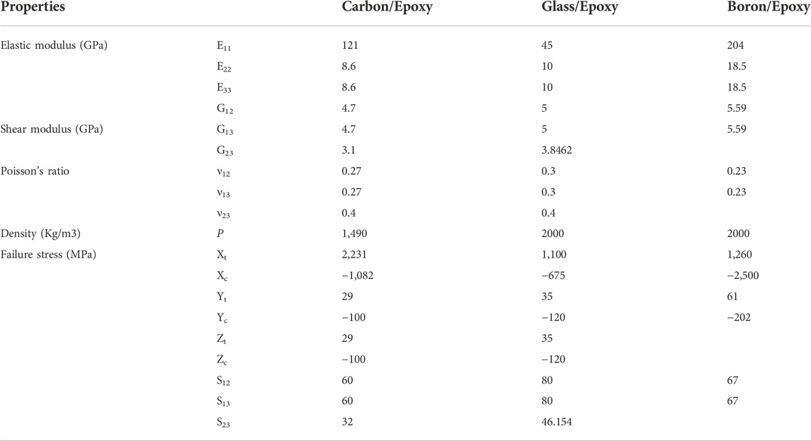
TABLE 1. Mechanical properties of the composite materials (ANSYS, 2017).
3.1 Verification of example 1
For the verification of the mathematical model derived above. Results obtained from FOSDT were compared with ANSYS WORKBENCH, and results from the previous literature for simple submersible shells. The mean radius and length of each composite cylindrical shell were 7.5 inches, and the thickness of each shell was 0.0212 inches. The material considered had the properties as follows:
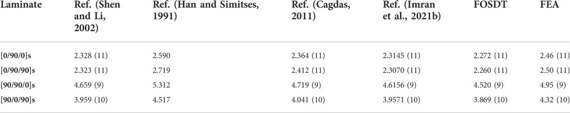
TABLE 2. Results of buckling pressure (psi) from the verification example 1.
In Table 2, the results were compared with the work done by Shen, Han, Cadges, and Imran. Column 1 shows the configuration of the laminate, column 2 shows the results from Shen, column 3 shows the results obtained by Han, Column 4 shows the results obtained by Cages and column 5 shows the results obtained by Imran. In the next columns, results obtained by FOSDT and FEA, respectively, are written. The results were compared with the previous studies and FEA. Different angle configurations were changed, and the results were examined. In all calculations, the value of m was fixed to 1, and n was changed. For the configuration [0/90/0]s, and in the case of FOSDT, the percentage difference was recorded 2.4%, 13.99%, 4.04%, 1.87% with respect to Shen, Han, Cadges and Imran. For the configuration of [0/90/90]s, the difference was examined 2.78%, 20.3%, 6.72% and 2.79% respectively. When the configuration was changed to [90/90/0]s, the percentage difference was recorded 3.075%, 17.52%, 4.40% and 2.11% respectively. For the last configuration of [90/0/90]s, the values were 2.32%, 16.74%, 4.44% and 2.22% respectively. The percentage difference between the present FOSDT and FEA was recorded 8.27% for the configuration of [0/90/0]s and it was increased to 10.61% for the configuration of [0/90/90]s. [90/90/0]s configuration shows the percentage difference of 9.51% whereas the last configuration of [90/0/90]s shows the percentage difference of 11.65%.
3.2 Verification of example 2
Table 3 shows the outcomes of the authentication study for buckling pressure attained by using the FOSDT-based mathematical model and ANSYS with those of the previous studies. The dimensions and materials are the same and are taken from example 1.
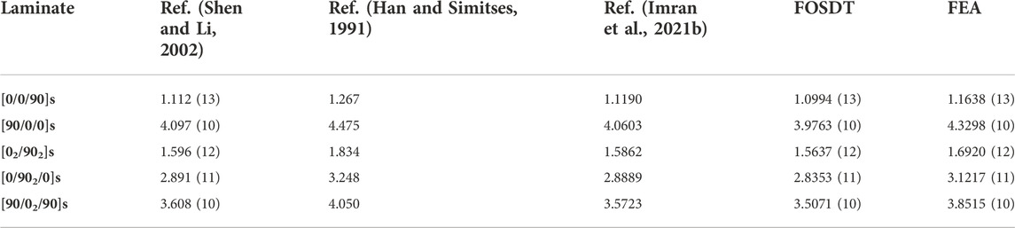
TABLE 3. Results of buckling pressure (psi) from verification example 2.
In Table 3, the results were compared with the work done by Shen, Han, and Muhammad Imran. For the configuration of [0/0/90]s, the difference was recorded 1.1%, 15.24% and 1.78% respectively. In all cases, the value of m was fixed to 1. When configuration was changed to [90/0/0]s the percentage difference was recorded 3.03%, 12.54% and 2.11% respectively. Double angle configuration [02/902]s shows the percentage difference of 2.06%, 17.28% and 1.43% respectively. Single double angle configuration of [0/902/0]s shows the percentage difference of 1.96%, 14.55%, and 1.89%. And the last configuration of [90/02/90]s shows the percentage difference of 2.87%, 15.65% and 1.85% respectively.
3.3 Analysis of different configurations
MATLAB code was developed for the theory developed above for the composite shells. To check the accuracy range, different types of composite shells, including moderately thick, thick, long, and short composite shells were investigated. Three types of materials, Carbon/Epoxy, Glass/Epoxy, and Boron/Epoxy, were used with different cross-ply symmetric and unsymmetrical angle configurations. The layups used for the analysis are [0/90/0]s, [90/0/90/0]s, [02/902]s, [90/02/90]s, [0/902/0]s, [0/0/0/90]s [90/90/90/0]s and [0/90]. The external pressure was set at 1 MPa for all the calculations. The radius to thickness ratio
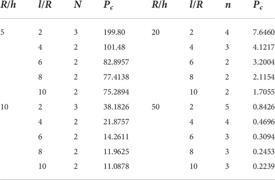
TABLE 4. Critical pressure values with [0/90/0]s configuration and Carbon/Epoxy composite (MPa).
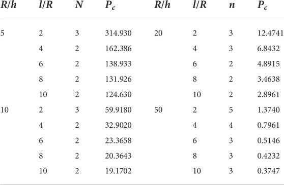
TABLE 5. Critical pressure values with [0/90/0]s configuration and Boron/Epoxy composite (MPa).
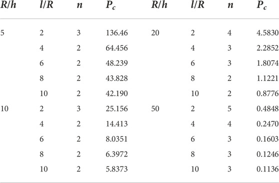
TABLE 6. Critical pressure values with [0/90/0]s configuration and Glass/Epoxy composite (MPa).
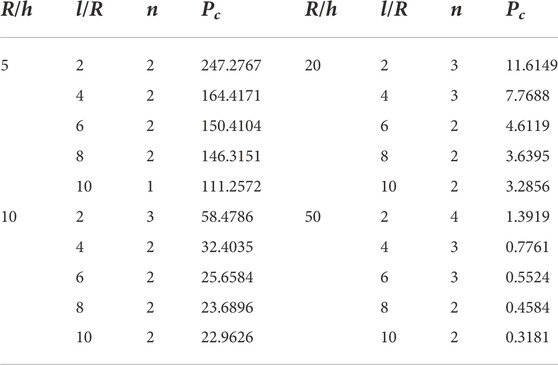
TABLE 7. Critical pressure values with [90/0/90/0]s configuration and Carbon/Epoxy composite (MPa).
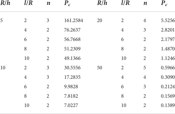
TABLE 8. Critical pressure values with [02/902]s configuration and Carbon/Epoxy composite (MPa).
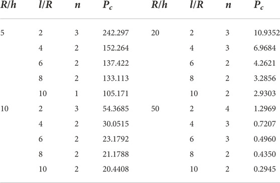
TABLE 9. Critical pressure values with [90/02/90]s configuration and Carbon/Epoxy composite (MPa).
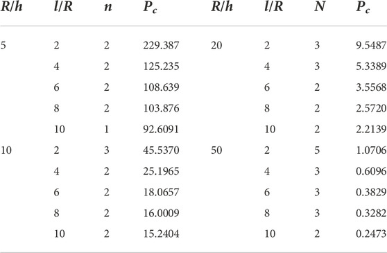
TABLE 10. Critical pressure values with [0/902/0]s configuration and Carbon/Epoxy composite (MPa).
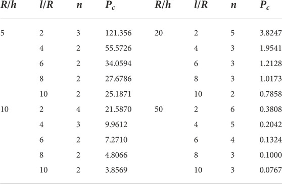
TABLE 11. Critical pressure values with [0/0/0/90]s configuration and Carbon/Epoxy composite (MPa).
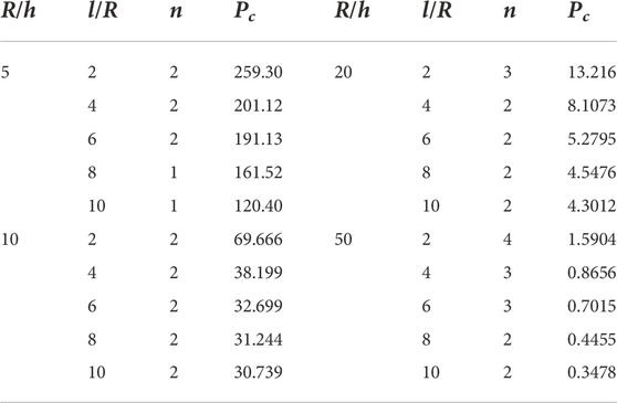
TABLE 12. Critical pressure values with [90/90/90/0]s configuration and Carbon/Epoxy composite (MPa).
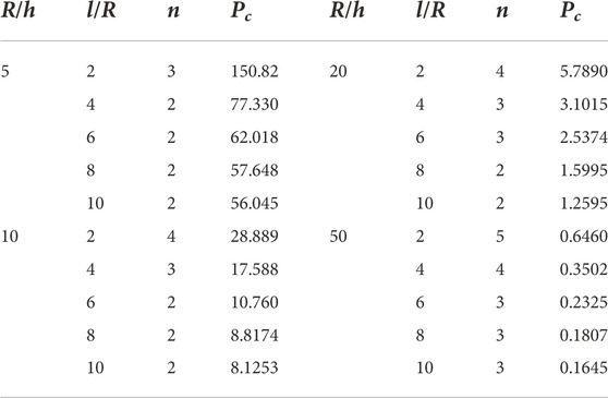
TABLE 13. Critical pressure values with [0/90] configuration and Carbon/Epoxy composite (MPa).
Table 4 shows the results from Carbon/Epoxy [0/90/0]s configuration. For
Now for the same symmetric configuration and changing the composite material to Boron/Epoxy, Table 5 shows the values of critical pressures on different
Table 6 shows the results with the same symmetric configuration and different composite materials. Boron/Epoxy was replaced by Glass/Epoxy, and it was examined from the results that the value of critical pressure was 136.46 MPa for
It is clear from the study that how results change by changing the material of the shells. But when the composite fiber ply angles are changed, it also affects and results are changed even when the same material is used. Different angles were changed in a symmetric and nonsymmetrical manner to examine the changes. Table 7 shows the results from the Carbon/Epoxy [90/0/90/0]s configuration. For
Table 8 shows the results from [02/902]s configuration. The values were decreased as compared with the previous configuration. For thick and short shells, the value of critical pressure was decreased to 161.2584 MPa and for long shells the value was dropped to 49.1366 MPa. For moderately thick and short shells, the value of critical pressure was recorded 30.5556 MPa and the value of n on this point was 3. For moderately thick and long shells, the value of critical pressure was recorded 7.0227 MPa. For thin shells when the
Table 9 shows the results from the Carbon/Epoxy [90/02/90]s configuration. For
Table 10 shows the results from [0/902/0]s configuration. The values were decreased as compared with the previous configuration. For thick and short shells, the value of critical pressure was decreased to 229.387 MPa and for long shells the value was dropped to 92.6091 MPa. For moderately thick and short shells, the value of critical pressure was recorded 45.5370 MPa and the value of n on this point was 3. For moderately thick and long shells, the value of critical pressure was recorded 15.2404 MPa. For thin shells when the
Table 11 shows the results from [0/0/0/90]s configuration. The value of critical pressure was reduced to 121.356 MPa for thick and short shells. This configuration shows the lowest value of the critical pressure. For
Table 12 contains the results acquired from [90/90/90/0]s configuration. Changing the angles of the plies as compared with the previous configuration shows a huge difference in the results. The value of critical pressure for thick and short shells was more than double of the previous configuration and was equal to 259.30 MPa. The number of full waves in the circumferential direction were also decreased as compared with the previous configuration. For long shells on this thickness ratio, the value of critical pressure was recorded 120.40 MPa. For moderate thick shells, the values in case of short and long shells were recorded 69.666 MPa and 30.739 MPa respectively. For moderate thin shells, the values in case of short and long shells were recorded 13.216 MPa and 4.3012 MPa respectively. For thin shells with the thickness ratio of 50, the values in case of short and long shells were recorded 1.5904 MPa and 0.3478 MPa respectively. Table 13 gives the results attained from [0/90] configuration. The value of critical pressure for thick and short shells was equal to 150.82 MPa. For long shells on this thickness ratio, the value of critical pressure was recorded 56.045 MPa. For moderate thick shells, the values in case of short and long shells of ratio 2 and 10 were recorded 28.889 MPa and 8.1253 MPa respectively. For moderate thin shells, the values in case of short and long shells of ratio 2 and 10 were recorded 5.7890 MPa and 1.2595 MPa respectively. For thin shells with the thickness ratio of 50, the values in case of short and long shells of ratio 2 and 10 were recorded 0.6460 MPa and 0.1645 MPa respectively.
4 Conclusion
In this research work the analytical modeling of cross-ply submersible composite shell structure was presented. Four different types of shells i-e Thick, thin, long and short shells were investigated under hydrostatic pressure. The results of the modeling were compared with the previous studies. With the formulation given in the study, one can design the shells according to the user’s applications. It was clear from the results that the direction of the composite plies also has a large impact on the stability of the submersible composite shell. For thick and short shells with
Data availability statement
The raw data supporting the conclusion of this article will be made available by the authors, without undue reservation.
Author contributions
All authors listed have made a substantial, direct, and intellectual contribution to the work and approved it for publication.
Funding
This work is supported by the “National Natural Science Foundation of China and its grant number is 12172100”.
Conflict of interest
The authors declare that the research was conducted in the absence of any commercial or financial relationships that could be construed as a potential conflict of interest.
Publisher’s note
All claims expressed in this article are solely those of the authors and do not necessarily represent those of their affiliated organizations, or those of the publisher, the editors and the reviewers. Any product that may be evaluated in this article, or claim that may be made by its manufacturer, is not guaranteed or endorsed by the publisher.
References
Alarçin, V., and Alarcin, F. (2015). Using sandwich composite shells for fully pressurized tankson liquefied Petroleum Gas Carriers. Strojniški Vestn. - J. Mech. Eng. 62, 32–40. doi:10.5545/sv-jme.2015.2611
Almeida, J. H. S., Bittrich, L., Jansen, E., Tita, V., and Spickenheuer, A. (2019). Buckling optimization of composite cylinders for axial compression: A design methodology considering a variable-axial fiber layout. Compos. Struct. 222, 1–12. doi:10.1016/j.compstruct.2019.110928
Almeida, José Humberto S., Ribeiro, Marcelo L., Tita, Volnei, and Amico, S. C. (2017). Damage modeling for carbon fiber/epoxy filament wound composite tubes under radial compression. Compos. Struct. 160, 204–210. doi:10.1016/j.compstruct.2016.10.036
Asadi, E., Wang, W., and Qatu, M. S. (2012). Static and vibration analyses of thick deep laminated cylindrical shells using 3D and various shear deformation theories. Compos. Struct. 94, 494–500. doi:10.1016/j.compstruct.2011.08.011
Cagdas, I. U., and Adali, S. (2011). Buckling of cross-ply cylinders under hydrostatic pressure considering pressure stiffness. Ocean. Eng. 38, 559–569. doi:10.1016/j.oceaneng.2010.12.005
Cagdas, I. U. (2011). Stability analysis of cross-ply laminated shells of revolution using a curved axisymmetric shell finite element. Thin-Walled Struct. 49, 732–742. doi:10.1016/j.tws.2011.01.005
Craven, R., Graham, J. D-J., and Dalzel-Job, J. (2013). Conceptual design of a composite pressure hull. Ocean. Eng. 128, 153–162. doi:10.1016/j.oceaneng.2016.10.031
Davoud, S-G., and Rahimi, G. (2019). New analytical approach for buckling of composite sandwich pipes with iso-grid core under uniform external lateral pressure. Jnl. Sandw. Struct. Mater. 23, 65–93. doi:10.1177/1099636218821397
Ebrahimi, F., Hafezi, P., and Dabbagh, A. (2020). Buckling analysis of embedded graphene oxide powder-reinforced nanocomposite shells. Def. Technol. 17, 226–233. doi:10.1016/j.dt.2020.02.010
Fathallah, E. (2019). Finite element modelling and multi-objective optimization of composite submarine pressure hull subjected to hydrostatic pressure. Mater Sci. Forum 953, 53–58. doi:10.4028/www.scientific.net/msf.953.53
Fathallah, E., Qi, H., Tong, L., and Helal, M. (2014). Design optimization of composite elliptical deep-submersible pressure hull for minimizing the buoyancy factor. Adv. Mech. Eng. 2014, 987903. doi:10.1155/2014/987903
Fathallah, E., Qi, H., Tong, L., and Helal, M. (2014). Optimal design analysis of composite submersible pressure hull. Appl. Mech. Mat. 578, 89–96. doi:10.4028/www.scientific.net/AMM.578-579.89
Fathallah, E., Qi, H., Tong, L. H., and Helal, M. (2015). Design optimization of lay-up and composite material system to achieve minimum buoyancy factor for composite elliptical submersible pressure hull. Compos. Struct. 121, 16–26. doi:10.1016/j.compstruct.2014.11.002
Geier, B., and Singh, G. (1997). Some simple solutions for buckling loads of thin and moderately thick cylindrical shells and panels made of laminated composite material. Aerosp. Sci. Technol. 1, 47–63. doi:10.1016/S1270-9638(97)90023-7
Gheisari, M., Nezamabadi, A., and Khazaeinejad, P. (2017). On buckling of cylindrical shells under combined loading. J. Adv. Manuf. Technol. 11, 9–18.
Han, B., and Simitses, G. J. (1991). Analysis of anisotropic laminated cylindrical shells subjected to destabilizing loads. Part II: Numerical results. Compos. Struct. 19, 183–205. doi:10.1016/0263-8223(91)90022-Q
Imran, M., Shi, D., Tong, L., Elahi, A., Waqas, H. M., and Uddin, M. (2021a). Multi-objective design optimization of composite submerged cylindrical pressure hull for minimum buoyancy factor and maximum buckling load capacity. Def. Technol. 17, 1190–1206. doi:10.1016/j.dt.2020.06.017
Imran, M., Shi, D., Tong, L., and Waqas, H. M. (2019). Design optimization of composite submerged cylindrical pressure hull using genetic algorithm and finite element analysis. Ocean. Eng. 190, 106443. doi:10.1016/j.oceaneng.2019.106443
Imran, M., Shi, D., Tong, L., Elahi, A., and Uddin, M. (2021b). On the elastic buckling of cross-ply composite closed cylindrical shell under hydrostatic pressure. Ocean. Eng. 227, 108633. doi:10.1016/j.oceaneng.2021.108633
Konečný, B. M. (2013). Comparison of analytical and numerical fem solutions for buckling of laminated composite cylindrical shells. Czechia: Brno University of Technology.
Lam, K. Y., Zong, Z., and Wang, Q. (2003). Dynamic response of a laminated pipeline on the seabed subjected to underwater shock. Compos. Part B Eng. 34, 59–66. doi:10.1016/s1359-8368(02)00072-0
Liang, C-C., Chen, H-W., and Jen, C-Y. (2003). Optimum design of filament-wound multilayersandwich submersible pressure hulls. Ocean. Eng. 30, 1941–1967. doi:10.1016/s0029-8018(03)00044-1
Liu, T., Wang, A., Wang, Q., and Qin, B. (2020). Wave based method for free vibration characteristics of functionally graded cylindrical shells with arbitrary boundary conditions. Thin-Walled Struct. 148, 106580. doi:10.1016/j.tws.2019.106580
Lopatin, A. V., and Morozov, E. V. (2012). Buckling of a composite cantilever circular cylindrical shell subjected to uniform external lateral pressure. Compos. Struct. 94, 553–562. doi:10.1016/j.compstruct.2011.08.021
Lopatin, A. V., and Morozov, E. V. (2017). Buckling of composite cylindrical shells with rigid end disks under hydrostatic pressure. Compos. Struct. 173, 136–143. doi:10.1016/j.compstruct.2017.03.109
Messager, T., Pyrz, M., Gineste, B. C., and Chauchot, P. (2002). Optimal laminations of thin underwater composite cylindrical vessels. Compos. Struct. 58, 529–537. doi:10.1016/s0263-8223(02)00162-9
Moon, Chul-Jin, Kim, In-Hoon, Choi, Bae-Hyeon, Kweon, Jin-Hwe, and Choi, J-H. (2010). Buckling of filament-wound composite cylinders subjected to hydrostatic pressure for underwater vehicle applications. Compos. Struct. 92, 2241–2251. doi:10.1016/j.compstruct.2009.08.005
Qatu, M. S. (1999). Accurate equations for laminated composite deep thick shells. Int. J. Solids Struct. 36, 2917–2941. doi:10.1016/S0020-7683(98)00134-6
Qin, B., Zhong, R., Wang, T., Wang, Q., Xu, Y., and Hu, Z. (2020). A unified Fourier series solution for vibration analysis of FG-CNTRC cylindrical, conical shells and annular plates with arbitrary boundary conditions. Compos. Struct. 232, 111549. doi:10.1016/j.compstruct.2019.111549
Salahshour, S., and Fallah, F. (2018). Elastic collapse of thin long cylindrical shells under external pressure. Thin-Walled Struct. 124, 81–87. doi:10.1016/j.tws.2017.11.058
Semenov, A. (2021). Buckling of shell panels made of fiberglass and reinforced with an orthogonal grid of stiffeners. J. Appl. Comput. Mech. 7, 1856–1861. doi:10.22055/JACM.2021.37768.3078
Shaker, Khubab, Nawab, Yasir, Shahid, S., and Saouab, A. (2021). Thermal expansion coefficient: A macro-scale indicator of particle filtration in composites fabricated by resin infusion. Polym. Test. 96, 107083. doi:10.1016/j.polymertesting.2021.107083
Shakeri, M., Yas Mgg, M. H., and Gol, M. G. (2005). Optimal stacking sequence of laminated cylindrical shells using genetic algorithm. Mech. Adv. Mater. Struct. 12, 305–312. doi:10.1080/15376490590898501
Shen, H. S., and Li, Q. S. (2002). Postbuckling of cross-ply laminated cylindrical shells with piezoelectric actuators under complex loading conditions. Int. J. Mech. Sci. 44, 1731–1754. doi:10.1016/S0020-7403(02)00056-5
Shen, K. C., Pan, G., Jiang, J., Li, Z., and Wei, R. F. (2018). “Design optimization of composite cylindrical shell under hydrostatic pressure,” in 2018 OCEANS - MTS/IEEE Kobe Techno-Oceans (OTO), Kobe, Japan, 28-31 May 2018 1–5. doi:10.1109/OCEANSKOBE.2018.8559064
Shi, D., He, D., Wang, Q., Ma, C., and Shu, H. (2020). Free vibration analysis of closed moderately thick cross-ply composite laminated cylindrical shell with arbitrary boundary conditions. Mater. (Basel) 13, 884. doi:10.3390/ma13040884
Sofiyev, A. H., and Kuruoglu, N. (2014). Buckling and vibration of shear deformable functionally graded orthotropic cylindrical shells under external pressures. Thin-Walled Struct. 78, 121–130. doi:10.1016/j.tws.2014.01.009
Thai, H-T., and Choi, D-H. (2013). A simple first-order shear deformation theory for laminated composite plates. Compos. Struct. 106, 754–763. doi:10.1016/j.compstruct.2013.06.013
Timarci, T., and Soldatos, K. P. (2000). Vibrations of angle-ply laminated circular cylindrical shells subjected to different sets of edge boundary conditions. J. Eng. Math. 37, 211–230. doi:10.1023/A:1004794513444
Topal, U. (2009). Multiobjective optimization of laminated composite cylindrical shells for maximum frequency and buckling load. Mat. Des. 30, 2584–2594. doi:10.1016/j.matdes.2008.09.020
Venhrynyuk, M., Dalyak, T., Shatskyi, I., Venhrynyuk, T., and Velychkovych, A. (2021). Stress analysis in damaged pipeline with composite coating. Appl. Sci. (Basel). 11, 10676. doi:10.3390/app112210676
Wang, Q., Shao, D., and Qin, B. (2018). A simple first-order shear deformation shell theory for vibration analysis of composite laminated open cylindrical shells with general boundary conditions. Compos. Struct. 184, 211–232. doi:10.1016/j.compstruct.2017.09.070
Waqas, M. H., Shi, D., Imran, M., Khan, Z. S., Tong, L., Ahad, E. F., et al. (2019). Conceptual design of composite sandwich structure submarine radome. Materials 12, 1966. doi:10.3390/ma12121966
Keywords: submersible shells, first order shear deformation theory, composite shells, stability formulation, elastic buckling
Citation: Waqas HM, Shi D, Khan SZ, Helal M and Fathallah E (2022) Analytical modeling of cross-ply cylindrical composite submersible shell with elastic buckling using first order shear deformation theory. Front. Mater. 9:1004752. doi: 10.3389/fmats.2022.1004752
Received: 27 July 2022; Accepted: 13 October 2022;
Published: 02 December 2022.
Edited by:
Yasir Nawab, National Textile University, PakistanReviewed by:
Hamid M. Sedighi, Shahid Chamran University of Ahvaz, IranRaja Muhammad Waseem Ullah Khan, National Textile University, Pakistan
Copyright © 2022 Waqas, Shi, Khan, Helal and Fathallah. This is an open-access article distributed under the terms of the Creative Commons Attribution License (CC BY). The use, distribution or reproduction in other forums is permitted, provided the original author(s) and the copyright owner(s) are credited and that the original publication in this journal is cited, in accordance with accepted academic practice. No use, distribution or reproduction is permitted which does not comply with these terms.
*Correspondence: Hafiz Muhammad Waqas, aGFmaXp3YXFhc0BocmJldS5lZHUuY24=; Dongyan Shi, c2hpZG9uZ3lhbkBocmJldS5lZHUuY24=
†These authors have contributed equally to this work and share first authorship
‡These authors have contributed equally to this work and share senior authorship
§These authors have contributed equally to this work and share last authorship