 Xie Renjun
 Wu Zhiqiang1,2*
 Cheng Xiaowei
 Ni Xiucheng
- 1CNOOC Research Institute Co. Ltd., Beijing, China
- 2School of Safety and Ocean Engineering, China University of Petroleum, Beijing, China
- 3School of New Energy and Materials, Southwest Petroleum University, Chengdu, China
- 4State Key Laboratory of Oil and Gas Reservoir Geology and Exploitation, Southwest Petroleum University, Chengdu, China
Poor mechanical integrity of cement sheaths during the production of oil and gas wells may cause air channeling and water channeling issues in the wells, leading to severe safety problems, and adversely affecting the safety and efficiency of the oil and gas resources production. This article focuses on a low-density cement slurry system with added floating beads. The compressive strength and flexural strength of cement stones, the mechanical integrity of cement rings, and triaxial mechanical properties were assessed. The optimal dosage of floating beads and the evolution of the cement stone’s mechanical properties and deformation ability were discussed. Bonding strengths of the first and the second interfaces were evaluated using the shrinkage test results of the cement mortar. Finally, the microscopic mechanism of the change in mechanical properties was analyzed by scanning electron microscopy. The results showed that the cement mortar exhibited the best compressive strength, mechanical integrity, and deformability after blending with 15% floating beads. At the same time, the volume shrinkage of the cement mortar mixed with 15% floating beads was the smallest, only 0.00667%, plausibly indicating good bonding with a casing and the formation to reduce the occurrence of gas channeling. Finally, the microscopic test of the cement mortar showed that the bonding between floating beads and cement was not tight, so internal cracks in the cement easily developed along the bonding part of cement and floating beads. The more floating beads were mixed, the more likely was cement mortar destroyed.
Introduction
Annulus compression zone and gas channeling are challenging (Bu et al., 2016; Zhao et al., 2018; Zeng et al., 2019; Bu et al., 2020a; Bayanak et al., 2020) problems in the development and production of oil and gas wells because cement rings are subjected to casing internal pressure (Bu et al., 2020b; Guo et al., 2020; Kuanhai et al., 2020; Kuanhai et al., 2021) and formation stress (Su et al., 2022). The failure of its mechanical integrity (Wang and Taleghani, 2014; Omosebi et al., 2017) leads to damage, cracks, and the appearance of micro-annular gaps on the cemented surface, yielding annulus packing failure (Yousuf et al., 2021), introducing enormous safety hazards to the later exploitation of oil and gas wells. In cementing formations with a low pressure coefficient and easy leakage, especially in fracture-type and cave-type carbonate formations (Wang et al., 2021), it is very easy to cause a loss of circulation if a conventional cement slurry with a density of about 1.9 g/cm3 is used for cementing, yielding inadequate cementing quality and cementing failure. At this time, the use of low-density cement slurry for cementing has become a good choice.
Low-density cement slurries are commonly used (Jiapei et al., 2018; Du et al., 2019; Velayati et al., 2019; Li et al., 2020; Rao et al., 2021; Vipulanandan and Maddi, 2021), yielding a lower density of the cement slurry system. At the same time, the density of a foamed cement slurry increases rapidly with pressure, so the actual density of the foamed cement slurry is not low under the bottom conditions of a well. Moreover, foamed cement slurry requires more sophisticated equipment, which is nowadays difficult to achieve in China. Therefore, it is necessary to adopt new design methods or materials to improve low-density cement slurries’ performance under low-density conditions (Adjei et al., 2021; Murthy et al., 2021).
At present, scholars use cement, floating beads, micro-silica, and cellulose fibers to study low-density cement slurry systems (Li et al., 2014; Cheng et al., 2018). The main purpose is to use the principle of particle grading to optimize the particle size distribution between the cement slurry and low-density filling materials and to maximize the accumulation ratio between materials and reduce the gaps between material particles. This may reduce the water-cement ratio and improve the overall performance of the cement slurry system. Floating beads have high strength and can be well dispersed in cement slurry. At the same time, floating beads can effectively reduce the density of cement slurry, and the cost is lower. Therefore, this manuscript selects floating beads as the admixture material. However, the research on the mechanical properties of floating beads and low-density cement systems is still in its initial phase, and there are only a few studies on the failure analysis of the mechanical integrity of cement rings (Santra and Sweatman, 2011; Kuanhai et al., 2020).
This study simulates the density of cement slurry at different formation temperatures and pressures and explores the effect of different amounts of floating beads on the mechanical properties of low-density cement slurry systems. The macroscopic mechanical integrity is analyzed through the compressive strength test of cement stones, the mechanical integrity test after high-temperature and high-pressure curing, the triaxial cyclic load test, and the volume shrinkage test. Finally, the microscopic features that affect mechanical integrity are assessed by scanning electron microscopy. This study represents a guide toward applying low-density cement slurries in cementing operations in formations with a low pressure coefficient and easy leakage.
Experimental
Raw Materials
1) Glass G oil well cement was provided by Jiahua Special Cement Co., Ltd.; chemical components and mineral compositions are shown in Table 1.
2) Floating beads and micro-silica were provided by Chengdu Omega Petroleum Technology Co., Ltd. The macro morphology is shown in Figure 1.
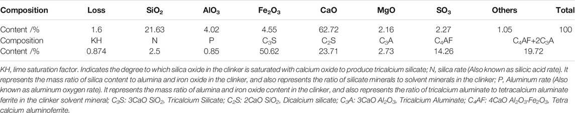
TABLE 1. Chemical composition and mineral composition of the Glass G oil well cement.
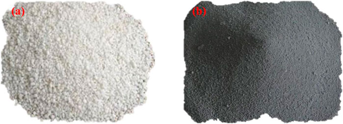
FIGURE 1. Macro-morphology of floating beads (A) and macro-morphology of micro-silica (B) 105 (3) Additives, mainly fluid loss agent G33S and dispersant USZ, were provided by Weihui 106 Chemical Co., Ltd.
Floating beads are a kind of high-strength and very hard fly ash glass hollow microspheres, which are spherical in shape and have a closed and smooth surface. Floating beads are composed of inert components. The main chemical components are shown in Table 2. They have fine particles, high strength, high temperature resistance, and wear resistance. The natural particle size is about 1–250 microns; the specific surface area is about 300–360 cm2/g; it is mainly gray-white, with thin and hollow walls and very light weight. The density of floating beads is 2.10–2.20 g/cm3. As a lightening agent, the incorporation of floating beads will significantly reduce the density of cement slurry. The blending of floating beads can improve the rheology of cement slurry, increase durability, and reduce shrinkage deformation. At the same time, the dispersion of floating beads in the cement slurry is the same as that of most mineral fillers. Because of its wall thickness and high compressive strength, it can withstand the shearing effect of the high-speed mixing of the mixer.

TABLE 2. Chemical composition and percentage of the floating beads and micro-silica.
The main component of micro-silica is SiO2, with an average particle size of 0.1–0.3 μm. It is an amorphous spherical particle with a smooth surface. Its chemical composition is shown in Table 2. It is a pozzolanic substance with a large specific surface area (approximately: 20–28 m2/g) and high activity. After adding Portland cement, it can effectively improve the strength and corrosion resistance of cement-based materials.
3) Additives, mainly fluid loss agent G33S and dispersant USZ, were provided by Weihui Chemical Co., Ltd.
Experimental Methods
Sample Preparation and Curing
Cement slurry was prepared according to GB/T 19,139–2012 “Oil Well Cement Test Method” (Standard C N., 2012) and API RP 10B Standard “Oil Well Cement Material and Experiment Specification” (Institute A P, 2013). The performance of the cement slurry was tested referring to GB/T 10238-2015 “Oil Well Cement” (Standard C N., 2015). The prepared slurry was cured in a cube mold (50.8 mm × 50.8 mm × 50.8 mm) for 1d, 3d, and 7d, and then tested for its compressive strength with a TY-300 pressure testing machine. The loading rate is 2 KN/min±0.2 KN/min. The tensile strength test of cement stone is carried out in accordance with the Brazilian split tensile test method. The TY-300 pressure testing machine was used to test the splitting tensile strength of the columnar (Φ50.8 mm × 25.4 mm) cement stone. The loading rate is 20 N/min ±2 N/min.
Sample Testing and Analysis
The phase composition of cement stone is tested by dx-2000 X-ray diffractometer (Dandong Haoyuan Instrument Co., Ltd.): The test angle range is 5–70°, the pace is 0.04°/s, and the test equipment voltage and current are 30 kV and 20 mA, respectively. The micro morphology of the cement stone was tested with ZEISS EV0 MA15 scanning electron microscope (Carl Zeiss, Germany): Resolution: high vacuum mode, 3.0 nm (30kV); magnification: 5X-300000X; acceleration voltage: 0.3–30 kV. S8 TIGER X-ray fluorescence spectrometer (Bruck AXS, Germany) was used to test the mineral composition and chemical composition of the samples at 25°C, with an applicable power supply of 380V ± 10%, a frequency of 50HZ, and an external argon supply with a purity of 99.999%. An external UPS power supply was utilized in order to prevent sudden power failures and damages to the instrument. The RTR-1000 triaxial rock mechanics tester (CCTS, United States) was used to perform triaxial compression test on the sample to determine its stress-strain curve at 20 °C with a confining pressure of 20.7 MPa. GY-ASE1000L cement slurry shrinkage-expansion dual-purpose instrument was used to test the volume shrinkage of the slurry. The volume of the slurry cup used was 240 ml, and the volume shrinkage rate of the slurry was tested for 24 h at 60 °C and 20 MPa.
Test Method for the Mechanical Integrity of Cement Rings
1) This study uses a cement ring integrity evaluation device developed by Chengdu Core Technology Co., Ltd. to assess the mechanical integrity, as shown in Figure 2.
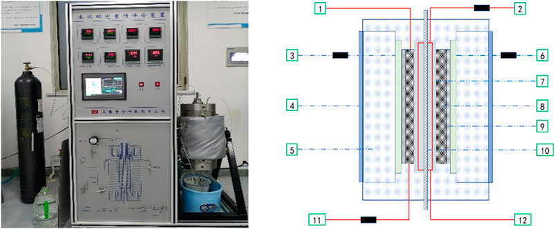
FIGURE 2. Mechanical integrity evaluation device of the cement ring and its equivalent schematic diagram.
The working principle of the device is first to put a cured cement ring into a rubber sleeve and use a pressurized pump to inject fluid (oil or water) into the annular space between the rubber sleeve and the kettle body. The actual temperature and pressure are transmitted to the cement ring through the rubber sleeve to simulate the effect of the formation pressure on the cement ring. Then, the set temperature of the heating jacket on the kettle wall was used to simulate the formation temperature. Pressure-relief pumps injected fluid (oil or water) into the casing to simulate the effect of pressure changes in the casing on the cement ring. Nitrogen gas was injected through the end-face of the cement ring to detect the sealing state of the cement ring in a real environment dynamically. By reading the pressure gauge, the display value of the gas flow meter, and checking whether the gas cylinder shows some bubbles, it can be determined whether the cement ring is damaged or even destroyed under this condition.
1- High-pressure nitrogen bottle 2-Temperature sensor collector 3-Confining pressure water injection pump 4-Heating jacket 5-Kettle body wall 6-Internal pressure booster pump 7-Sleeve 8-Cement ring 9-Sealing rubber sleeve 10-Metal rod 11-Gas flow sensor collector 12-Internal pressure booster pump.
2) The test process is shown in Figure 3.
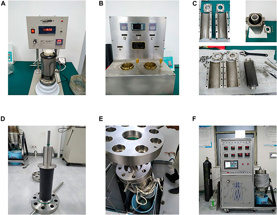
FIGURE 3. Test process for cement ring integrity: (A) Preparation of cement slurry, (B) Cement slurry prefabrication, (C) Mold assembly and molding, (D) Cement ring assembly, (E) Instrument assembly, (F) conducting of the experiment.
The cement ring was prepared using a special mold and then placed in an integrity evaluation instrument, and the experimental conditions and parameters were set to evaluate the mechanical integrity of the cement ring.
Results and Discussion
Influence of Floating Beads on the Performance of Cement Mortar
The amount of floating beads used in this article is 15, 18, 20, 23, and 25%. The amount of micro-silica is 15%, the amount of the fluid loss agent is 5%, the amount of dispersant is 1%, and the water-to-solid ratio is 0.5. The performance of the tested cement mortar is shown in Table 3. The experimental temperature is 30°C, 60°C, and 90°C, respectively.
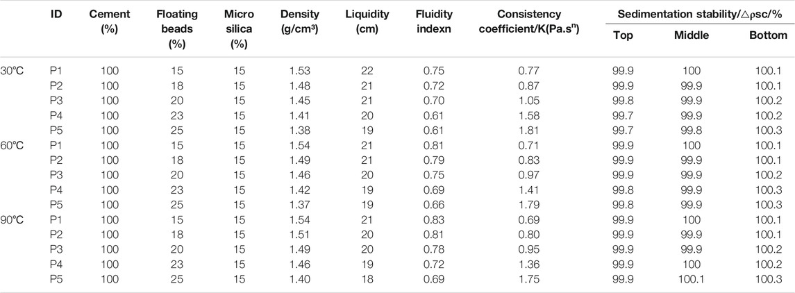
TABLE 3. Basic engineering performance of the cement slurry mixed with floating beads (mass fraction %).
As the amount of floating beads increases, the density and the fluidity of the cement mortar gradually decrease, while its viscosity increases. At the same time, the stability of the slurry is relatively good. Under the three temperatures tested in the experiment, the difference in cement slurry engineering performance is not significant, and the overall performance is good, which can meet the requirements of on-site construction.
Influence of Floating Beads on the Strength of Cement Stones
Compressive Strength
For cement mortars with different amounts of floating beads, the compressive strength of cement stones cured at 30, 60, and 90°C for 1, 3, and 7 days was tested. The test results are shown in Figure 4.
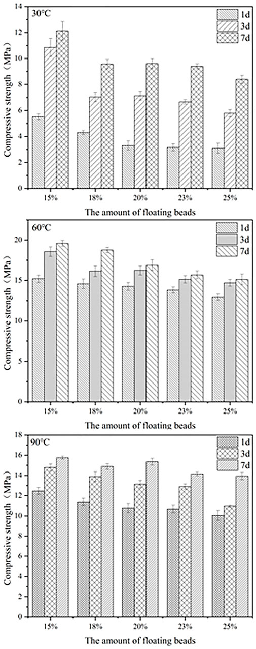
FIGURE 4. Compressive strength of cement stones.
According to Figure 4, the compressive strength of variously aged cement stones at three curing temperatures exhibits a downward with the amount of floating beads. Considering the properties of the slurry tested in Table 3, the density of the cement slurry gradually decreases with the amount of floating beads. Since the floating beads are hollow glass microspheres, they are filled with a large amount of air and thus lightweight, so they effectively reduce the density of the cement slurry after mixing. However, if too many floating beads are mixed in, they form defects in the cement stone, decreasing its strength.
As the curing temperature increases, the overall compressive strength of cement stones first increases and then decreases, being the highest after curing at 60°C. This can be explained by the gradually increased hydration rate inside the cement stone as the curing temperature increases, so more hydration products are generated, increasing the strength. When the curing temperature rises again, the cement hydration speed increases. At the same time, the micro-silica inside the slurry quickly hydrates. All these have caused the air bubbles in the cement stone to be unable to be discharged, thereby increasing the porosity of the cement stone, causing its internal shrinkage and reducing its compressive strength (Liu et al., 2021; Munjal et al., 2021; Pang et al., 2021). Therefore, the compressive strength of the cement stone cured at 90°C is lower than that of the cement stone cured at 60°C.
Flexural Strength
The flexural strength of cement stones mixed with different amounts of floating beads is shown in Figure 5 after curing for 7 days at different temperatures.
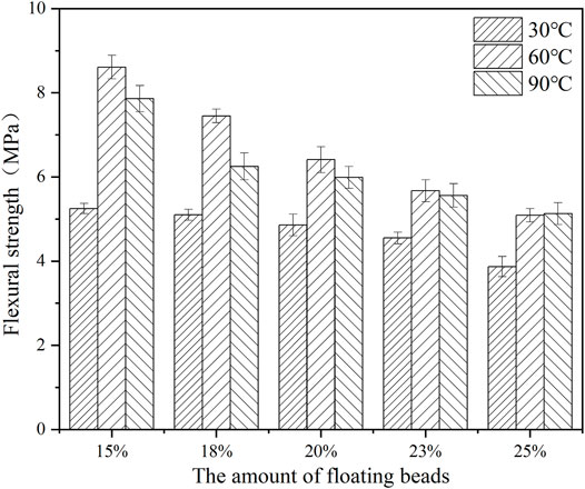
FIGURE 5. Flexural strength of cement stones.
According to Figure 5, the flexural strength of cement stones gradually decreases with the amount of floating beads. Plausibly, the main reason is that many floating beads form defects in the cement stone, deteriorating its mechanical properties. Under different curing temperatures, flexural strength shows the same behavior as compressive strength, so it is the highest after curing at 60°C.
Mechanical Integrity of Cement Rings
For the wellbore filled with cement slurry, the density of the wellhead cement slurry is the lowest, and the density of the cement slurry at the end of the well is the highest. To simulate the density of different formation heights and formation pressures, we use three density points to simulate downhole conditions. The amount of floating beads is 15, 20, and 25%, respectively. The macroscopic appearance of cement rings is shown in Figure 6 after curing for 7 days in a pressurized curing kettle. Subsequently, the mechanical integrity test of cement rings was performed. The morphology of cement rings after failure is shown in Figure 7, and the test parameters and results are shown in Table 4.
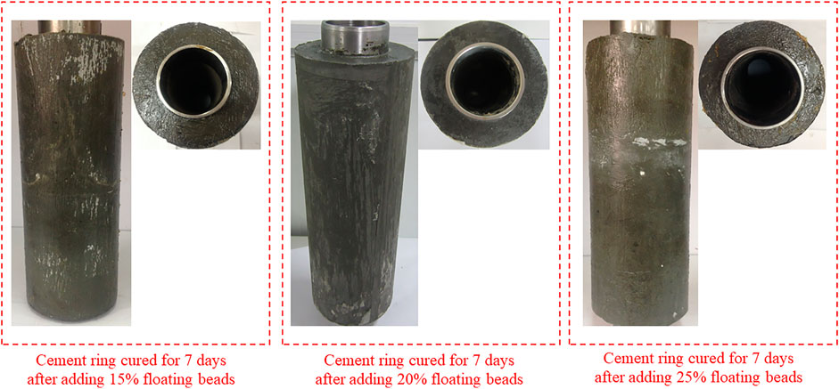
FIGURE 6. Macro-morphology of cement rings with different amounts of floating beads after curing at 60 °C for 7 days.
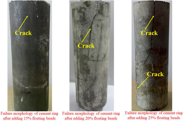
FIGURE 7. Macro-morphology of cement rings with different amounts of floating beads after failure.
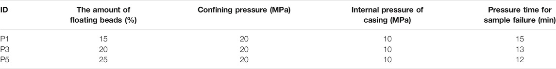
TABLE 4. Test parameters and test results of cement ring integrity.
Figure 6 shows that the integrity of cement rings with different amounts of floating beads is good after curing for 7 days, and no cracks appear on the side and upper- and lower-end surfaces of the cement ring.
The cement ring is placed on the integrity evaluation device and confining pressure and internal pressure are introduced. When the cement ring structure is complete, the gas inside the device cannot pass through, so there is no change in the air pressure on the display instrument. When the gauge pressure changes, it indicates a channel in the cement ring, so the structural integrity is damaged. At the same time, the macroscopic damage morphology of cement rings in Figure 7 indicates that after the cement ring mixed with 15% float beads is destroyed, only a slight crack appears. However, the cement ring with 25% floating beads exhibits huge cracks that penetrate the entire cement ring. All three samples are completely destroyed. The difference in the size and shape of the cracks reflects the difference in the cohesion of the samples, and the difference in the failure time mirrors the differences in the strength of the samples. According to Table 4, under the same pressure, the failure time of the cement ring shows a downward trend with the amount of floating beads, implying that as the amount of floating beads increases, the strength of the cement ring decreases, the mechanical integrity becomes worse, and the cement ring is more easily damaged in the down part. As a result, the cement ring is ineffective in the downhole packing, and gas channeling occurs.
Stress-Strain Curve of Cement Stones
The cement stone square mold was cured in a pressurized curing kettle for 7 days, cored, and then subjected to a triaxial mechanical test. The test confining pressure was 20.7 MPa. The test results are shown in Figure 8.
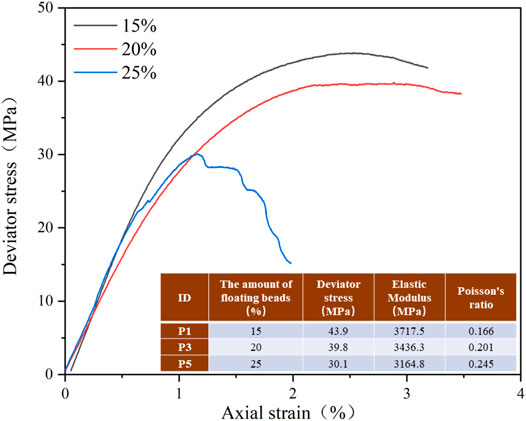
FIGURE 8. Stress-strain curve of cement stones.
According to Figure 8, the peak stress of the cement stone mixed with 15% floating beads is the highest, 43.9 MPa, indicating that it exhibits the highest strength. The modulus of elasticity is 3.7175 GPa, which is 17.46% higher than 3.1648 GPa with 25% floating beads. The modulus of elasticity measures the ability of a material to resist elastic deformation. The deformability of cement stone mixed with 15% floating beads is lower than that of cement stone mixed with 25% floating beads. This is because after a large number of floating beads are mixed into cement stone, its smooth outer surface and spherical shape can play a certain lubricating effect, thereby increasing the deformability of the cement stone. At the same time, the Poisson ratio of the cement stone mixed with 15% floating beads is the lowest, implying that under the same axial strain, the deformation in the second direction is the smallest.
Volume Shrinkage Performance of Cement Stones
The prepared cement slurry was directly poured into a slurry cup with a volume of 240 ml and placed in a high-temperature and high-pressure volume change rate device to test volume shrinkage performance. The experimental parameters and experimental results are shown in Table 5.
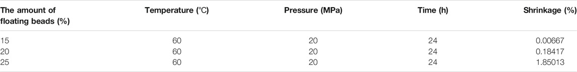
TABLE 5. Test parameters and results of the volume shrinkage of cement stones.
After the volume shrinkage of the cement stone, the cementation quality of the first and the second cementing interfaces decreases, and micro-annular gaps and microcracks form at the interface, thereby providing gas channels. The higher the volume shrinkage rate, the greater the possibility of micro-annular gaps, micro-cracks, and gas channeling. According to Table 5, the volume shrinkage rates of the cement stones mixed with 15, 20, and 25% floating beads are 0.00667, 0.18417, and 1.85013%, respectively. As the amount of floating beads increases, the shrinkage rate of cement stones gradually rises, facilitating the production of micro-annular gaps and cracks at the interface, causing gas channeling.
Cement Stone Phase Analysis
Figure 9 shows the phase composition of the cement stone cured at 60°C for 7 days with different amounts of floating beads.
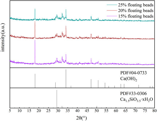
FIGURE 9. Phase analysis of the cement stone with different amounts of floating beads.
According to Figure 9, there is no difference in the types of the cement hydration products after adding different amounts of floating beads, and there are mainly calcium hydroxide and hydrated calcium silicate gel. Floating beads are chemically inert, do not participate in the cement hydration reaction, and will not cause cement stone phase change. As the amount of floating beads increases, the diffraction peak intensity of the hydration product decreases. This is because under the same conditions, a large amount of floating beads is filled in the cement hydration product. Therefore, in the test, under the same quality, there are less cement hydration products mixed with 25% floating beads (because it contains more floating beads), which leads to a certain degree of reduction in diffraction peaks. At the same time, as main bearers of the internal skeleton of cement stones, hydration products play a decisive role in their mechanical properties. The smaller the amount of hydration products, the lower their relative strength. The XRD analysis results are consistent with the previous changes of the mechanical properties of cement stones with different amounts of floating beads.
Micro-morphological Characteristics of Cement Stones
The microscopic morphology of cement stones with different amounts of floating beads observed under a scanning electron microscope is shown in Figure 10.
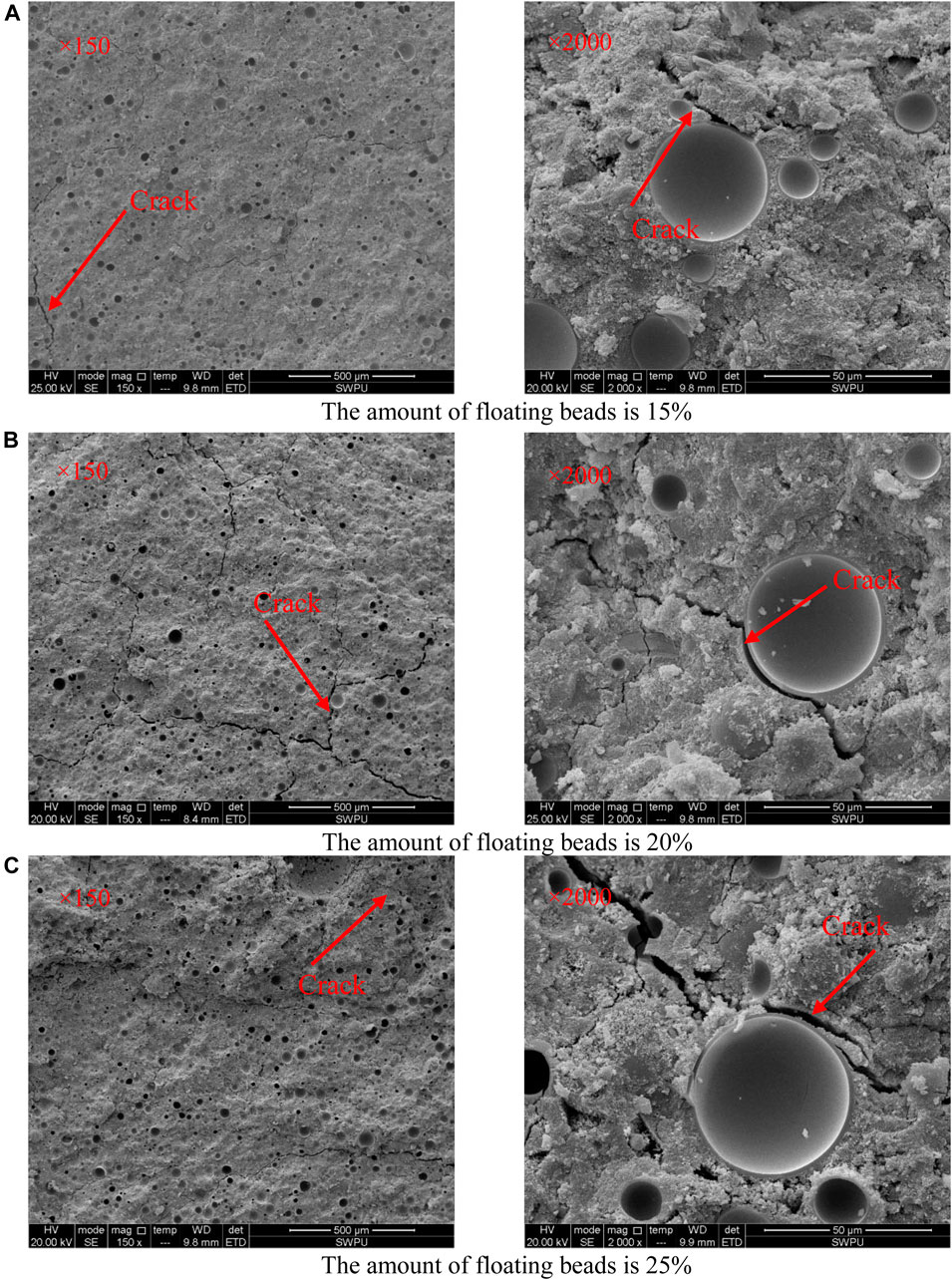
FIGURE 10. The microscopic morphology of cement stone mixed with different floating beads. (A) The amount of floating beads is 15%. (B) The amount of floating beads is 20%. (C) The amount of floating beads is 25%.
The cement stone exhibits microscopic cracks at the bonding position between the floating beads and the cement interface, showing that cement and floating beads are not tightly bonded. The part where floating beads and cement are combined can be considered a defect in the cement stone, deteriorating the mechanical properties of the cement stone. The direction of all the large cracks on the cross-section is where cement and the floating bead interface are bonded. There are defects in the low-density cement slurry system mixed with floating beads due to the loose association of floating beads and cement. The internal defects of the cement stone subjected to an external pressure load can easily develop along the bonding part of the cement and the floating beads, affecting the strength of the cement stone and causing the cement stone to be more prone to damage.
After mixing, floating beads are uniformly distributed inside the cement stone, and there is no large-scale agglomeration phenomenon, indicating that the dispersion of floating beads in the cement stone is relatively good. As the amount of floating beads increases, their distribution becomes denser, yielding more bonding surfaces between cement and floating beads and making defects more likely to appear in the cement stone. Cement stones subjected to external forces are more likely to be destroyed. The experimental results show that when the amount of floating beads is 15%, there are fewer internal defects and smaller cracks in the cement stone. At the same time, it can be seen from the previous experimental results that the cement stone with 15% floating beads has the highest compressive strength and the largest deviator stress.
Conclusion
This study simulates the density of cement slurry at different formation temperatures and formation pressures, discussing the mechanical properties of the low-density cement slurry system mixed with different amounts of floating beads. The following conclusions are obtained:
1) The performance of cement slurry slightly degrades after mixing with floating beads, but it meets the basic engineering performance requirements of cement slurry during cementing construction.
2) As the amount of floating beads increases, the strength of cement stone decreases. When the curing temperature is too high, the crystals formed inside the cement stone change, which in turn decreases strength. The cement stone exhibits the best compressive and flexural strength when the floating bead content is 15%, and the curing temperature is 60°C.
3) The experimental results of the mechanical integrity of cement stone indicate that the cement stone mixed with 15% floating beads withstands external force for the longest time, exhibits the smallest cracks after damage, having the best mechanical integrity.
4) Triaxial rock mechanics experiments show that the peak stress of cement stone mixed with 15% floating beads is the highest, indicating the highest strength.
5) The microscopic analysis shows that the bonding between cement and floating beads is not tight, so microscopic cracks appear at the joints, making cement stones more prone to failure when subjected to external forces.
Data Availability Statement
The original contributions presented in the study are included in the article/Supplementary Material, further inquiries can be directed to the corresponding authors.
Author Contributions
XR and WZ are responsible for the overall idea of the experiment, CX is responsible for providing experimental equipment and materials, and NX is responsible for experimental research and paper writing.
Funding
The authors appreciate the support of the CNOOC Limited Scientific Research Project “Ultra High Temperature and High Pressure Development Well Drilling and Completion Risk Assessment and Countermeasure Research” (No. YXKY-ZX-09–2021) and “Feasibility Study on Low Permeability Development of Bozhong 25- 1 Oilfield 5 Well Block and Sha 3 Member” (No. 2021FS-02).
Conflict of Interest
Author XR and WZ were employed by CNOOC Research Institute Co. Ltd.
This research is under the overall responsibility of CNOOC Research Institute Co., Ltd., with the assistance of the School of New Energy and Materials, Southwest Petroleum University. This research was funded by the CNOOC Ltd. scientific research project “Ultra High Temperature and High Pressure Development Well Drilling and Completion Risk Assessment and Countermeasures Research” (No. YXKY-ZX-09-2021) and “Feasibility Study on Low Permeability Development of Bozhong 25- 1 Oilfield 5 Well Block and Sha 3 Member” (No. 2021FS-02). The fund’s participation in this research is as follows: The fund provides research ideas, experimental equipment, materials, funds and other support for the research content of this article. The sponsor participated in the research design, data collection, analysis, interpretation, writing and submission of this article for publication. All authors declare no other conflicts of interest.
Publisher’s Note
All claims expressed in this article are solely those of the authors and do not necessarily represent those of their affiliated organizations, or those of the publisher, the editors and the reviewers. Any product that may be evaluated in this article, or claim that may be made by its manufacturer, is not guaranteed or endorsed by the publisher.
Acknowledgments
The authors would also like to thank the Advanced Cementing Materials Research Center of SWPU for their kind assistance with the experiments.
References
Adjei, S., Elkatatny, S., Sarmah, P., and Abdelfattah, A. M. (2021). Evaluation of Calcined Saudi Calcium Bentonite as Cement Replacement in Low-Density Oil-Well Cement System. J. Pet. Sci. Eng. 205, 108901. doi:10.1016/j.petrol.2021.108901
Bayanak, M., Zarinabadi, S., Shahbazi, K., and Azimi, A. (2020). Effects of Nano Silica on Oil Well Cement Slurry Charactreistics and Control of Gas Channeling. South Afr. J. Chem. Eng. 34, 11–25. doi:10.1016/j.sajce.2020.05.006
Bu, Y., Du, J., Guo, S., Liu, H., and Huang, C. (2016). Properties of Oil Well Cement with High Dosage of Metakaolin. Construction Building Mater. 112, 39–48. doi:10.1016/j.conbuildmat.2016.02.173
Bu, Y., Ma, R., Du, J., Guo, S., Liu, H., and Zhao, L. (2020). Utilization of Metakaolin-Based Geopolymer as a Mud-Cake Solidification Agent to Enhance the Bonding Strength of Oil Well Cement-Formation Interface. R. Soc. Open Sci. 7 (2), 191230. doi:10.1098/rsos.191230
Bu, Y., Ma, R., Guo, S., Du, J., Liu, H., and Cao, X. (2020). A Theoretical Evaluation Method for Mechanical Sealing Integrity of Cementing Sheath. Appl. Math. Model. 84, 571–589. doi:10.1016/j.apm.2020.03.001
Cheng, X. W., Khorami, M., Shi, Y., Liu, K. Q., Guo, X. Y., Austin, S., et al. (2018). A New Approach to Improve Mechanical Properties and Durability of Low-Density Oil Well Cement Composite Reinforced by Cellulose Fibres in Microstructural Scale. Construction Building Mater. 177, 499–510. doi:10.1016/j.conbuildmat.2018.05.134
Du, J., Bu, Y., Shen, Z., and Cao, X. (2019). A Novel Fluid for Use in Oil and Gas Well Construction to Prevent the Oil and Gas Leak from the Wellbore. Construction Building Mater. 217, 626–637. doi:10.1016/j.conbuildmat.2019.05.100
Guo, S., Bu, Y., Yang, X., Wang, C., Guo, B., and Sun, B. (2020). Effect of Casing Internal Pressure on Integrity of Cement Ring in marine Shallow Formation Based on XFEM. Eng. Fail. Anal. 108, 104258. doi:10.1016/j.engfailanal.2019.104258
Institute A P (2013). API RP 10B-2, Recommended Practice for Testing Well cements[S]. Washington: American Petroleum Institute publishing services
Jiapei, D., Yuhuan, B., Xuechao, C., Zhonghou, S., and Baojiang, S. (2018). Utilization of Alkali-Activated Slag Based Composite in deepwater Oil Well Cementing. Construction Building Mater. 186, 114–122. doi:10.1016/j.conbuildmat.2018.07.068
Kuanhai, D., Xie, P., Yue, Y., Dezhi, Z., Qiong, L., and Yuanhua, L. (2021). Study on the Effect of Interface Failure between Casing and Cement Sheath on Casing Stress under Non-uniform In-Situ Stress. Appl. Math. Model. 91, 632–652. doi:10.1016/j.apm.2020.10.007
Kuanhai, D., Yue, Y., Yi, H., Zhonghui, L., and Yuanhua, L. (2020). Experimental Study on the Integrity of Casing-Cement Sheath in Shale Gas wells under Pressure and Temperature Cycle Loading. J. Pet. Sci. Eng. 195, 107548. doi:10.1016/j.petrol.2020.107548
Li, H., Xu, D., Feng, S., and Shang, B. (2014). Microstructure and Performance of Fly Ash Micro-beads in Cementitious Material System. Construction Building Mater. 52, 422–427. doi:10.1016/j.conbuildmat.2013.11.040
Li, T., Huang, F., Li, L., Zhu, J., Jiang, X., and Huang, Y. (2020). Preparation and Properties of Sulphoaluminate Cement-Based Foamed concrete with High Performance. Construction Building Mater. 263, 120945. doi:10.1016/j.conbuildmat.2020.120945
Liu, H., Bu, Y., Zhou, A., Du, J., Zhou, L., and Pang, X. (2021). Silica Sand Enhanced Cement Mortar for Cementing Steam Injection Well up to 380 °C. Construction Building Mater. 308, 125142. doi:10.1016/j.conbuildmat.2021.125142
Munjal, P., Hau, K. K., and Hon Arthur, C. C. (2021). Effect of GGBS and Curing Conditions on Strength and Microstructure Properties of Oil Well Cement Slurry. J. Building Eng. 40, 102331. doi:10.1016/j.jobe.2021.102331
Murthy, R. V. V. R., Mohammad, F., and Chavali, M. (2021). Development of Innovative Lightweight Slurry in Oil Well-Cementing Operations. Upstream Oil Gas Techn. 7, 100045. doi:10.1016/j.upstre.2021.100045
Omosebi, O., Maheshwari, H., Ahmed, R., Shah, S., and Osisanya, S. (2017). Experimental Study of the Effects of CO 2 Concentration and Pressure at Elevated Temperature on the Mechanical Integrity of Oil and Gas Well Cement. J. Nat. Gas Sci. Eng. 44, 299–313. doi:10.1016/j.jngse.2017.04.009
Pang, X., Sun, L., Sun, F., Zhang, G., Guo, S., and Bu, Y. (2021). Cement Hydration Kinetics Study in the Temperature Range from 15 °C to 95 °C. Cement Concrete Res. 148, 106552. doi:10.1016/j.cemconres.2021.106552
Rao, F., Zhang, Z., and Ye, G. (2021). Three-dimensional Mesoscale Modeling of Foamed Cement Paste Using Peridynamics. Construction Building Mater. 310, 125230. doi:10.1016/j.conbuildmat.2021.125230
Santra, A., and Sweatman, R. (2011). Understanding the Long-Term Chemical and Mechanical Integrity of Cement in a CCS Environment. Energ. Proced. 4, 5243–5250. doi:10.1016/j.egypro.2011.02.503
Standard C N. (2015). Standard GB/T 10238-2015: General Administration of Quality Supervision. Inspection and Quarantine of the People’s Republic of China and Standardization Administration of China. Beijing: China Standards Press.
Standard C N. (2012). Standard GB/T 19139-2012: General Administration of Quality Supervision. Inspection and Quarantine of the People’s Republic of China and China National Standardization Administration. Beijing: China Standards Press.
Su, A., Chen, H., Feng, Y.-x., Zhao, J.-x., Wang, Z., Hu, M., et al. (2022). In Situ U-Pb Dating and Geochemical Characterization of Multi-Stage Dolomite Cementation in the Ediacaran Dengying Formation, Central Sichuan Basin, China: Constraints on Diagenetic, Hydrothermal and Paleo-Oil Filling Events. Precambrian Res. 368, 106481. doi:10.1016/j.precamres.2021.106481
Velayati, A., Roostaei, M., Rasoolimanesh, R., Soleymani, M., and Fattahpour, V. (2019). Colloidal Gas Aphron (CGA) Based Foam Cement System. Pet. Exploration Dev. 46 (6), 1281–1287. doi:10.1016/s1876-3804(19)60281-8
Vipulanandan, C., and Maddi, A. R. (2021). Characterizing the thermal, Piezoresistive, Rheology and Fluid Loss of Smart Foam Cement Slurries Using Artificial Neural Network and Vipulanandan Models. J. Pet. Sci. Eng. 207, 109161. doi:10.1016/j.petrol.2021.109161
Wang, W., and Taleghani, A. D. (2014). Three-dimensional Analysis of Cement Sheath Integrity Around Wellbores. J. Pet. Sci. Eng. 121, 38–51. doi:10.1016/j.petrol.2014.05.024
Wang, Y., Liu, K., and Gao, D. (2021). Investigation of the Interface Cracks on the Cement Sheath Stress in Shale Gas wells during Hydraulic Fracturing. J. Pet. Sci. Eng. 205, 108981. doi:10.1016/j.petrol.2021.108981
Yousuf, N., Olayiwola, O., Guo, B., and Liu, N. (2021). A Comprehensive Review on the Loss of Wellbore Integrity Due to Cement Failure and Available Remedial Methods. J. Pet. Sci. Eng. 207, 109123. doi:10.1016/j.petrol.2021.109123
Zeng, Y., Lu, P., Zhou, S., Sang, L., Liu, R., and Tao, Q. (2019). A New Prediction Model for Hydrostatic Pressure Reduction of Anti-gas Channeling Cement Slurry Based on Large-Scale Physical Modeling Experiments. J. Pet. Sci. Eng. 172, 259–268. doi:10.1016/j.petrol.2018.09.035
Keywords: low-density cement slurry, floating beads, annular air channeling, mechanical integrity, interface cementation
Citation: Renjun X, Zhiqiang W, Xiaowei C and Xiucheng N (2022) Research on the Mechanical Integrity of Low-Density Cement Mortar. Front. Mater. 8:837348. doi: 10.3389/fmats.2021.837348
Received: 16 December 2021; Accepted: 24 December 2021;
Published: 28 January 2022.
Edited by:
Hanfeng Liang, Xiamen University, ChinaReviewed by:
Albert Kwan, The University of Hong Kong, Hong Kong SAR, ChinaJiapei Du, RMIT University, Australia
Copyright © 2022 Renjun, Zhiqiang, Xiaowei and Xiucheng. This is an open-access article distributed under the terms of the Creative Commons Attribution License (CC BY). The use, distribution or reproduction in other forums is permitted, provided the original author(s) and the copyright owner(s) are credited and that the original publication in this journal is cited, in accordance with accepted academic practice. No use, distribution or reproduction is permitted which does not comply with these terms.
*Correspondence: Wu Zhiqiang, d3V6aHEyQGNub29jLmNvbS5jbg==; Cheng Xiaowei , Y2hlbmd4d0Bzd3B1LmVkdS5jbg==