 Hanjie Hu1,2
 Bing Du
 Liming Chen
- 1College of Aerospace Engineering, Chongqing University, Chongqing, China
- 2Chongqing General Aviation Industry Group Co., Ltd., Chongqing, China
- 3Chongqing Key Laboratory of Nano–Micro Composite Materials and Devices, School of Metallurgy and Materials Engineering, Chongqing University of Science and Technology, Chongqing, China
In this study, a type of tube with an open-hole AL alloy tube nested outside the CFRP tube is designed and fabricated, and the energy absorbing characteristics and failure mechanism under quasi-static axial compression are discussed. It is found that the summing tube composed of two single tubes has less energy absorption than the hybrid tube. Numerical simulation and theoretical models are used to evaluate the influence of the hybrid tube in terms of cost and weight, and it is found that under the same energy absorption, the hybrid tube has a weight reduction of 39.2% compared to the open-hole AL tube, which was 25.7% of the cost of the CFRP tube. This hybrid structure has potential as the load-carrying and energy absorption tube.
1 Introduction
Thin-walled tubes have been found to have wide applications as crashworthy structures in the engineering field for their high structural efficiency and low usage cost (Lu and Yu, 2003; Du and Song, 2004; Zhang, 2008). An essential index of thin-walled structures is energy absorption which can be achieved by the plastic deformation of metal or fracture of composite material. Specific criteria should be followed in designing crashworthy structures—that is, higher energy absorption capacity, lower peak load value, and enough deformation displacement. Facing the lightweight development trend, the design of thin-walled tubes concerning the load-carrying ability, energy absorption, material cost, etc. is of more importance.
In recent years, efforts have been made to improve the crashworthiness of metal thin-walled tubes, such as cross-sectional design, variable thickness, inducing angle/groove, and opening hole (Baroutaji et al., 2017; Ha and Lu, 2020; Bhutada and Goel, 2021). Compared with the metal one, a composite thin-walled tube shows higher specific mechanical advantages and becomes a potential alternative as a crashworthy structure (Lau et al., 2012; Zhu et al., 2018; Isaac and Ezekwem, 2021). Metal/composite hybrid tubes can combine the stable deformation of metal and lightweight property of composite (Reuter and Tröster, 2017; Sun et al., 2018; Ma et al., 2019; Wang et al., 2020). It is found that hybrid tubes showed relatively better load-carrying and energy absorption characteristics than single tubes. Moreover, inducing open hole in thin-walled tubes has been found to be beneficial for improving crashworthiness characteristics (Liu et al., 2017; Liu et al., 2020; Ren et al., 2021).
In this study, the influence of open-hole and hybrid configuration on the load-carrying and energy absorption of tubes under axial compression will be explored. First, inducing hole is a design in the AL tube which is combined with the CFRP tube. Then, the quasi-static axial compression experiments are carried out to investigate the energy-absorbing characteristics and failure mechanism of three types of tubes, namely, open-hole AL, CFRP, and hybrid. Finally, the validated FE simulation and theoretical model are used to evaluate the cost and weight of the hybrid tube compared with single tubes.
2 Design, Fabrication, and Experiment
Design conception of the open-hole AL tube is shown in Figure 1. The open-hole ratio
where
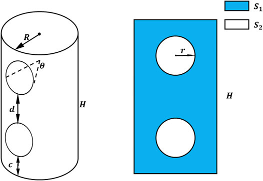
FIGURE 1. Dimensions of an open-hole AL tube.
The outer area of the tube and open hole is
AL tubes made of 6063-T5 whose properties are described in Table 1 are commercially bought, and holes are drilled by a CNC cutting machine as designed. CFRP tubes are supplied by Dezhou Carbon Fiber Composite Materials Co., Ltd. The length of the AL tube is 120 mm, the tube diameter is 64 mm, and the wall thickness is 2 mm. The length of the CFRP tube is 120 mm, the tube diameter is 59.8 mm, and the wall thickness is 1.9 mm. The hybrid tube is obtained by inserting the AL tube covered by film adhesive into the CFRP tube. Three kinds of tubes are shown in Figure 2. The radius of the open hole is 13.8 mm. A pair of holes is located at the upper and lower quarter points of the AL tube axially, and the other pair is symmetrically arranged.

TABLE 1. Al6063-T5 AL alloy material properties.
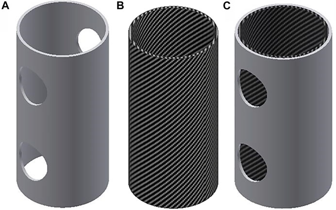
FIGURE 2. Three kinds of tubes: (A) open-hole AL, (B) CFRP, and (C) hybrid.
A universal testing machine (UTM5305STXL) with a load capacity of 300 kN is used to investigate the quasi-static axial compression properties of various tubes, namely, AL, open-hole AL, CFRP, and hybrid. These tubes are placed between the rigid steel plate with a diameter of 150 mm. Compression speed is chosen as 4 mm/min, and the maximum loading displacement of each specimen is 80 mm.
3 Result and Discussion
3.1 Crashworthiness Indices
Crashworthiness indices are considered including energy absorption
The
Peak crushing force
3.2 Single Tube
3.2.1 AL Tube
The load–displacement curve and the crushing process of AL tube are shown in Figure 3. With the increase of the crushing displacement, the load capacity of the AL tube decreases sharply after it reaches the peak load (107.7kN) because the AL tube processed by T5 has a higher strength and brittle fracture, which will make its minimum carrying capacity very small. As the upper pressure platen moves downward gradually, collapse of the AL tube was observed following with the second and third peak load. While the fragments produced in the previous crushing process impacted the remaining AL tube, the lower half of the AL tube touched the upper pressure platen and irregular wrinkles that resulted in an incomplete accordion deformation of the AL tube being created. Under the effect of these folds, the numerical value of the next wave crest will decrease.
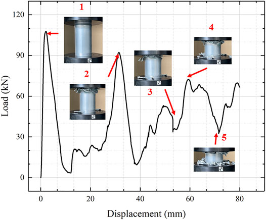
FIGURE 3. Load–displacement curve with deformation modes of the AL tube.
3.2.2 Open-Hole AL Tube
The load–displacement curve of the open-hole AL tube is shown in Figure 4, where the peak load of the open-hole AL tube is lower than that of the unopen-hole AL tube. The main reason is that the opened hole will guide the deformation of the AL tube and reduce the load. With the increase of the crushing displacement, the lower hole of the open-hole AL tube is crushed. The wrinkles produced by the guide hole will appear without contributing to the energy absorption of the open-hole AL tube. The upper part and the lower part of the round hole get contacted because the round hole at the bottom was destroyed. Dislocation occurred after a short contact time. The upper AL tube is in direct contact with the lower bottom plate. The contact between the upper and the lower AL tube results in a small bugle in the load–displacement curve, while the contact between the upper AL tube and the lower pressing platen enables the entire upper tube to continue to absorb energy so that the second peak occurs. Because the bottom of the AL tube is the irregular shape left by the lower round hole, the upper round hole has produced small deformation energy absorption. The existence of the round hole led to the entire AL tube to generate cracks from the right side of the round hole. The spread of the cracks makes the entire open-hole AL tube no longer have the capacity of absorbing energy. The upper hole of the open-hole AL tube has a regular deformation; however, the upper hole has irregular deformation when the shape of the AL tube was deformed. The energy absorption of this level model is very low, which belongs to a medium length collapse model.
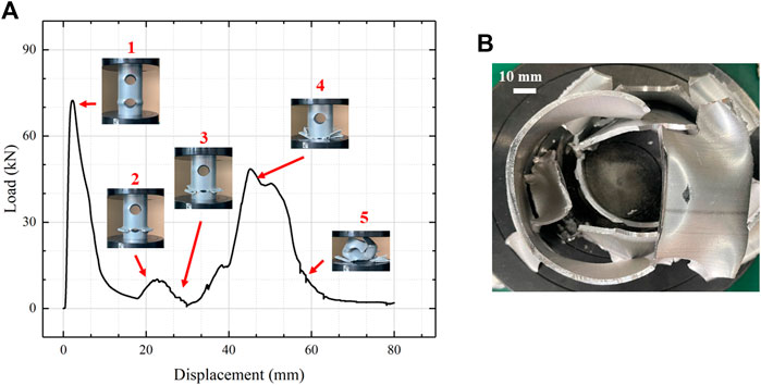
FIGURE 4. (A) Load–displacement curve with deformation modes of open-hole AL tube and (B) vertical view of the crushed open-hole AL tube.
3.2.3 CFRP Tube
The load–displacement curve of the CFRP tube under quasi-static compression and the entire crushing process is shown in Figure 5. The load–displacement curve shows a linear trend at the initial stage of crushing, and the curve drops instantly when it reaches the peak load (89.32kN). As the upper plate continues to move downward, the top area of the CFRP will generate a stress concentration area where many micro-cracks generally spread, and they will divide the CFRP tube into many sheet structures. Meanwhile, under the effect of layup, some sheet structures deform to the inside, while some deform outside of the tube, as shown in Figure 5B. After the stage of reaching the peak load, the entire CFRP tube is in the deformed state of mode I benefiting for the absorbing energy of the tube. The load–displacement curve shows that the whole energy absorption process of the CFRP tube is more stable than that of the AL tube. However, the brittle fracture of the CFRP tube makes its capacity of energy absorption to reduce greatly. The AL tube can be used to limit the CFRP tube in order to make the CFRP tube to become more compact and to improve the energy absorption capacity of the CFRP tube.
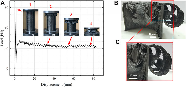
FIGURE 5. (A) Load–displacement curve with deformation modes of CFRP tube, (B) profile view of the crushed CFRP tube, and (C) detailed view.
3.3 Hybrid Tube
The deformation mode of the hybrid tube is complex, and its load–displacement curve and collapse process are shown in Figure 6. The same as the open-hole AL tube and CFRP tube, its initial curve still increases linearly to reach the peak load (128.92 kN). The top of the CFRP tube inside the hybrid tube did not deform, which is different from that of a single CFRP tube. This is because the restriction of the AL tube on the top prevents the CFRP tube from layering fracture. Through the bottom view and the load–displacement curve, the lower hole of the AL tube started to undergo deformation for energy absorption; the inside of the CFRP tube deforms from the lower part, and both the deformations result in a decrease in peak load. As the compression displacement gradually increases, the inside of the CFRP tube starts to produce cracks. As the crack spreads, the outer AL tube gradually compresses the lower round hole until the round hole disappears.
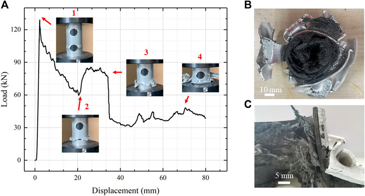
FIGURE 6. (A) Load-displacement curve with deformation modes of hybrid tube, (B) Vertical view of the crushed hybrid tube, and (C) Profile view.
Differing from the open-hole AL tube, the outer AL tube cannot undergo dislocation because of the high strength of the CFRP tube inside. After the lower round hole disappears, the upper AL tube and the lower AL tube are in direct contact, increasing the mean crushing force. The CFRP tube takes the main responsibility of absorbing energy in the whole hybrid tube, and the mean crushing force of the hybrid tube is also higher than the mean crushing force of a single CFRP tube with stable deformation. This also confirms the feasibility of limiting brittle fracture of CFRP tubes with external AL tubes to improve the energy absorption level. As the AL tube is compressed and compacted gradually, its energy absorption and load–displacement curve also rise gradually. Compared with the single tube, the mutual restriction of the mixed tube increases the capacity of absorbing energy. The mutual restriction makes the performance of the material to be further exerted, and the high strength of the CFRP tube also improves the energy absorption level of the open-hole tube.
3.4 Comparison
The load–displacement curves of all three samples are shown in Figure 7. It can be clearly seen that the load-carrying capacity of the hybrid tube is higher than that of all single AL or CFRP tubes in the half crushing process. All the crashworthiness indices mentioned above are shown in Table 3. To better explore the influence between the AL tube and CFRP tube, a simple sum of the open-hole AL tube and the CFRP tube was carried out. The deformation of the AL tube happened with fragment. By comparing Figures 4–6, we can see that during the crushing process, the deformation state of the two tubes that comprise the hybrid tube is of great difference to that of only the single tube. It can be seen from Figure 5B that the CFRP tube produces sheet structures that are bent in two directions under the axial compression. As a result, the CFRP tube absorbs energy mainly from the delamination and friction between the layered sheets and the upper pressure platen. Axial crushing makes the CFRP tube to generate cracks and transverse fractures, while the axial fibers on each sheet are still together. It was obvious that these axial fibers in a single CFRP tube are not fully utilized to absorb energy. However, it is opposite for the hybrid tube as shown in Figure 6B due to the constraint of the outer AL tube. The inward laminating and curling sheets gradually lose their ability to absorb energy, while the rest of the sheet continues to absorb energy. With the increase of crush displacement, the AL tube starts to generate plastic deformation, and the upper part and the lower part of the AL tube are in contact with each other. Since it cannot be dislocated inward, the mean crushing force is further increased. Differing from the open-hole AL tube, the upper open-hole did not deform until the end of the compression test.
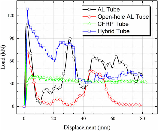
FIGURE 7. Load–displacement curve of four investigated tubes.
The load–displacement curves of the hybrid tube and the corresponding addition of two single tubes (open-hole AL tube and CFRP tube) are compared in Figure 8. The results show that the restraint between the AL tube and the CFRP tube is beneficial to energy absorption. It can be seen from Table 2 that total energy absorption of the hybrid tube is 10.5% higher than the sum of the two single tubes. Except for the deformation of the upper part of the open-hole tube, the hybrid tube in the remaining area is higher than the sum of the two single tubes. The reason why the energy absorption capacity can be improved is not only because of the complex interaction between the two tubes but also because of the great change in their deformation pattern. Although the SEA of CFRP tubes is relatively high, the CFE of CFRP tubes is relatively low due to the high peak load. The CFE of hybrid tubes is higher than that of all the other tubes.
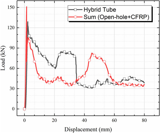
FIGURE 8. Comparison of hybrid tube and the sum of open-hole and CFRP tubes in the load–displacement curve.
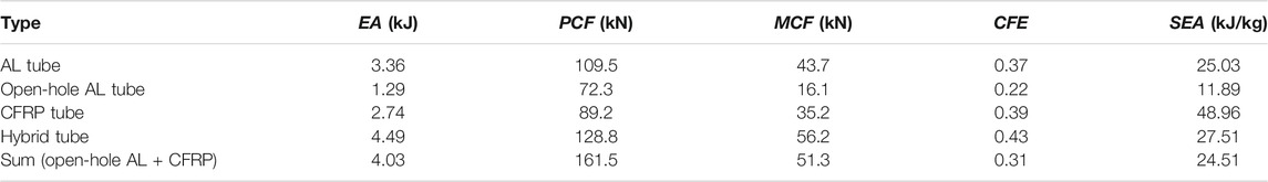
TABLE 2. Crashworthiness index of all specimens.
4 Comparison of Weight and Cost
Considering the same
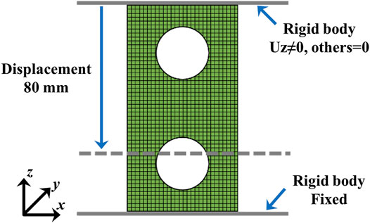
FIGURE 9. Sketch of simulation setup.
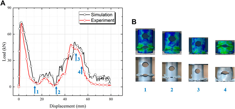
FIGURE 10. Comparison of simulation and experimental results in (A) the load–displacement curve and (B) deformation modes.
Then, the thickness of the open-hold AL tube was changed as 3, 3.5, and 4 mm. Correspondingly, the
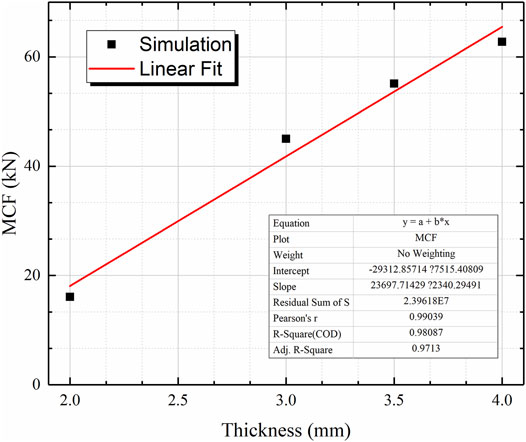
FIGURE 11. Fitting curve of mean crushing force of the open-hole AL tube based on verified simulation results.
The analytical model to predict the
where
where
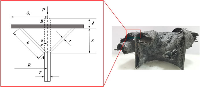
FIGURE 12. Analysis model of the CFRP tube subjected to axial compression.
In order to get the same
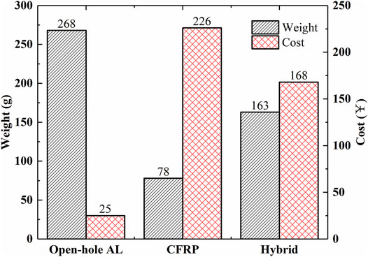
FIGURE 13. Comparison of open-hole, CFRP, and hybrid tubes in weight and cost.
5 Conclusion
In this study, the design of thin-walled tubes concerning the load-carrying ability, energy absorption, and material cost was conducted. A type of tube with an open-hole AL alloy tube nested outside the CFRP tube is designed and fabricated, and the energy absorbing characteristics and failure mechanism under quasi-static axial compression are discussed. It is found that the summing tube composed of two single tubes has less energy absorption than the hybrid tube. Numerical simulation and theoretical model are used to evaluate the influence of the hybrid tube in terms of cost and weight, and it is found that under the same energy absorption, the hybrid tube has a weight reduction of 39.2% compared to the open-hole AL tube, which is 25.7% of the cost of the CFRP tube. This hybrid structure with an opening hole has potential as the load-carrying and energy absorption tube.
Data Availability Statement
The raw data supporting the conclusion of this article will be made available by the authors, without undue reservation.
Author Contributions
HH performed conceptualization and writing—original draft. BD performed writing—review and editing, funding acquisition, and supervision. WJ contributed to software and investigation. CZ contributed to software and validation. NZ contributed to methodology. JL contributed to visualization. LC performed writing—review and editing.
Funding
Supports from the Chongqing Natural Science Foundation (cstc2018jcyjAX0089), Science and Technology Research Program of Chongqing Municipal Education Commission (KJQN202101531), and the Research Foundation of Chongqing University of Science and Technology (ckrc2019024) are gratefully acknowledged.
Conflict of Interest
HH was employed by the company Chongqing General Aviation Industry Group Co., Ltd.
The remaining authors declare that the research was conducted in the absence of any commercial or financial relationships that could be construed as a potential conflict of interest.
Publisher’s Note
All claims expressed in this article are solely those of the authors and do not necessarily represent those of their affiliated organizations, or those of the publisher, the editors, and the reviewers. Any product that may be evaluated in this article, or claim that may be made by its manufacturer, is not guaranteed or endorsed by the publisher.
References
Baroutaji, A., Sajjia, M., and Olabi, A.-G. (2017). On the Crashworthiness Performance of Thin-Walled Energy Absorbers: Recent Advances and Future Developments. Thin-Walled Structures 118, 137–163. doi:10.1016/j.tws.2017.05.018
Bhutada and, S., and Goel, M. D. (2021). Crashworthiness Parameters and Their Improvement Using Tubes as an Energy Absorbing Structure: an Overview. Int. J. Crashworthiness, 1–32. doi:10.1080/13588265.2021.1969845
Boria, S., Pettinari, S., and Giannoni, F. (2013). Theoretical Analysis on the Collapse Mechanisms of Thin-Walled Composite Tubes. Compos. Structures 103, 43–49. doi:10.1016/j.compstruct.2013.03.020
Du, X., and Song, H. (2004). Impact Dynamics and Crashworthiness Design of Cylindrical shell[M]. Beijing, China: Science Press.
Ha, N. S., and Lu, G. (2020). Thin-walled Corrugated Structures: A Review of Crashworthiness Designs and Energy Absorption Characteristics. Thin-Walled Structures 157, 106995. doi:10.1016/j.tws.2020.106995
Isaac, C. W., and Ezekwem, C. (2021). A Review of the Crashworthiness Performance of Energy Absorbing Composite Structure within the Context of Materials, Manufacturing and Maintenance for Sustainability. Compos. Structures 257, 113081. doi:10.1016/j.compstruct.2020.113081
Lau, S. T. W., Said, M. R., and Yaakob, M. Y. (2012). On the Effect of Geometrical Designs and Failure Modes in Composite Axial Crushing: A Literature Review. Compos. structures 94 (3), 803–812. doi:10.1016/j.compstruct.2011.09.013
Liu, Q., Liufu, K., Cui, Z., Li, J., Fang, J., and Li, Q. (2020). Multiobjective Optimization of Perforated Square CFRP Tubes for Crashworthiness. Thin-Walled Structures 149, 106628. doi:10.1016/j.tws.2020.106628
Liu, Q., Ma, J., Xu, X., Wu, Y., and Li, Q. (2017). Load Bearing and Failure Characteristics of Perforated Square CFRP Tubes under Axial Crushing. Compos. Structures 160, 23–35. doi:10.1016/j.compstruct.2016.10.032
Ma, Q., Zhou, Q., Gan, X., Wen, W., and Meng, Z. (2019). Research Progress of Metal/carbon Fiber Composites Reinforced Mixed Thin-Walled Pipe[J]. Eng. Plast. Appl. 47, 128–134. doi:10.3969/j.issn.1001-3539.2019.08.027
Ren, Y., Ran, T., Nie, L., and Jiang, H. (2021). Energy-absorption Assessments of Perforated CFRP Tube Induced by Inward-Splaying Trigger with Different Trigger Radius. Thin-Walled Structures 167, 108236. doi:10.1016/j.tws.2021.108236
Reuter, C., and Tröster, T. (2017). Crashworthiness and Numerical Simulation of Hybrid Aluminium-CFRP Tubes under Axial Impact. Thin-Walled Structures 117, 1–9. doi:10.1016/j.tws.2017.03.034
Sun, G., Wang, Z., Hong, J., Song, K., and Li, Q. (2018). Experimental Investigation of the Quasi-Static Axial Crushing Behavior of Filament-Wound CFRP and Aluminum/CFRP Hybrid Tubes. Compos. Structures 194, 208–225. doi:10.1016/j.compstruct.2018.02.005
Wang, Z., Jin, X., Li, Q., and Sun, G. (2020). On Crashworthiness Design of Hybrid Metal-Composite Structures. Int. J. Mech. Sci. 171, 105380. doi:10.1016/j.ijmecsci.2019.105380
Zhang, X. (2008). Crashworthiness Analysis and Design Optimization of Light Thin-Walled structures[D]. Dalian: Dalian University of Technology.
Keywords: composite tube, axial crushing, crashworthiness, numerical simulation, integrated design
Citation: Hu H, Du B, Jiang W, Zheng C, Zhu N, Liu J and Chen L (2022) Integrated Design in Load Carrying and Energy Absorption of Composite Tube. Front. Mater. 8:824016. doi: 10.3389/fmats.2021.824016
Received: 28 November 2021; Accepted: 20 December 2021;
Published: 12 January 2022.
Edited by:
Haibo Kou, Xi’an University of Science and Technology, ChinaReviewed by:
Liyong Jia, First aircraft institute of AVIC, ChinaXianhe Zhang, Shijiazhuang Tiedao University, China
Copyright © 2022 Hu, Du, Jiang, Zheng, Zhu, Liu and Chen. This is an open-access article distributed under the terms of the Creative Commons Attribution License (CC BY). The use, distribution or reproduction in other forums is permitted, provided the original author(s) and the copyright owner(s) are credited and that the original publication in this journal is cited, in accordance with accepted academic practice. No use, distribution or reproduction is permitted which does not comply with these terms.
*Correspondence: Bing Du, ZHViaW5nQGNxdXN0LmVkdS5jbg==; Liming Chen, Y2xtMDdAY3F1LmVkdS5jbg==