 Jinhe Gao
 Jiahuan Xi1
 Baokui Chen
95% of researchers rate our articles as excellent or good
Learn more about the work of our research integrity team to safeguard the quality of each article we publish.
Find out more
ORIGINAL RESEARCH article
Front. Mater. , 10 January 2022
Sec. Structural Materials
Volume 8 - 2021 | https://doi.org/10.3389/fmats.2021.821299
This article is part of the Research Topic Advanced Steel and Composite Structures in Civil Engineering View all 9 articles
To avoid brittle fracture and plastic yielding of steel beam-to-column connections under earthquakes, a new beam-to-column connection of steel structures with all-steel buckling restrained braces (BRBs) is proposed. The all-steel BRB is connected to the steel beam and column members through pins to form a new connection system. Taking the T-shaped beam-to-column connection steel structure as the research object, two structural types with an all-steel BRB installed on one side (S-type) and two sides (D-type) are considered. Theoretical equations of the connection system’s initial stiffness and yield load are derived through the mechanical models. The yield load, main strain distribution, energy dissipation, and stiffness of the connection system are investigated through quasi-static tests to verify the connection system’s seismic performance. The tests revealed that the proposed new connection system is capable of achieving a stable hysteresis behavior. At the end of loading, the beam and column members are not damaged, and the plastic deformation is concentrated in the plastic energy dissipating replaceable BRB, and the beam and column basically remain elastic. The proposed equations approximately estimated the load response of the proposed connection system. The results show that the damage mode of this new connection system under seismic loading is BRB yielding, with an elastic response from the beam-column members.
Earthquakes are a critical reason for structural damage and collapse, and the structural responses under seismic loads are complex and diverse (Li et al., 2016; Xie and Qu, 2016; Chen et al., 2021a; Chen et al., 2021b). In the Northridge earthquake in the United States in 1994 and the Hanshin Awaji earthquake in Japan in 1995, many brittle fractures occurred in the beam-to-column connections of traditional steel frames, which seriously threatened the overall threat stability of the structure (Li et al., 1998). After that, research on steel structure beam-to-column connections has been extensively carried out. Among them, the reduced beam section moment connections and the reinforced moment connections are both moved outwardly through plastic hinges, using sacrificial yielding at beam ends to dissipate dynamic response energy (Han et al., 2011; Sherven and Maryam, 2012; Tsavdaridis et al., 2012; Erfani et al., 2016; Liu et al., 2017; Shi et al., 2017). However, repairing the plastic damage in steel beams results in the disruption of the building function and expensive repair costs (Qu et al., 2017; Chen. et al., 2021c).
In recent years, a new type of connection system has attracted the attention of many scholars. This connection combines the damper with the beam-column connection. It uses the excellent energy dissipation capacity of the damper, which can not only achieve the effect of damping but also realize the rapid repair of the structural system after the earthquake. For example, Tomokazu and Masamichi (2004) proposed a welded reduced beam-to-column moment connection with the damper, and Koetaka et al. (2005) suggested a new type of moment connection with a π shaped metal damper. Liu (2008) conducted a numerical simulation and experimental comparative study on prestressed fabricated concrete frame beam-column connections with new lead dampers. Mander et al. (2009) proposed a new moment connection with the prestressed lead extrusion damper. Wu Z. P et al. (2020) proposed a PC frame structure system with sector lead-viscoelastic damper (SLVD), in which the SLVD not only protects the wet connection but also absorbs input energy in earthquakes. Chen. et al. (2021d) reinforced the brick-wood structure with the purlin roof by installing the damping-limit devices at the overlap connection of gables and wooden purlins. Li et al. (2021) proposed a novel beam-column connection using a metallic damper that was easy to be assembled and disassembled, and the plastic damage of the beam-column connections was concentrated in the metallic damper. It should be noted that the viscoelastic dampers exhibit significant temperature dependence, and the energy dissipation performance of the dampers degrades severely when the temperature increases.
Among the existing dampers, the metal damper is one of the most effective and economical energy dissipation mechanisms (Oh et al., 2009). As a kind of metal damper, BRBs make full use of the hysteretic energy dissipation capacity of steel and have excellent seismic performance, which makes BRBs robust options for a diversity of applications in seismic regions (Guo et al., 2016; Alexander et al., 2019; Mohamad and Seyed, 2020; Wu C. X et al., 2020). Because it does not need to be filled with mortar and concrete, all-steel BRBs are considered lightweight, and they are easier and faster to manufacture, transport, install, inspect, disassemble, and replace (Hamid and Shahrokh, 2017). Suita et al. (2003); Chou et al. (2004); Byakuno et al. (2004); Terashima et al. (2007) put forward a type of bolted beam to column connections with buckling restrained knee brace dampers and carried out a series of analyses and research on its mechanical properties. The dampers they chose use I-beam steel plates as the energy dissipation inner core, which has a simple structure, but its flexural stiffness is minor, so it is not the optimal structure form.
To avoid brittle fracture and plastic yielding of steel beam-to-column connections under earthquakes, a new type of connection system that adopts the mechanical connection equipped with the new all-steel BRB as the beam-to-column connection is proposed in this study. The introduction of a new all-steel BRB with a cruciform-section inner core in beam-column connections can improve the seismic performance of the structure and easy to repair after an earthquake. In this paper, the connection’s structural form and mechanical properties are discussed, and the quasi-static tests are conducted on the joint specimens of two structural forms. The primary purpose is to verify that the new connection has an energy dissipation capacity and lays the foundation for the subsequent improvement and development of the structure. At the same time, the mechanical behavior of the whole connection system is also theoretically evaluated, and a mathematical model is established to provide stiffness and yield load prediction.
The new connection system comprises an H-shaped steel beam, an H-shaped steel column, connecting angle steel, and BRB. In the existing beam-column connection, with the help of the full bolt connection form of arranging the angle steel at the beam flange, the initial defects caused by welding can be effectively avoided. Moreover, the connection’s bearing and deformation capacity can be effectively improved. The new BRB used to absorb energy is connected to the mainframe by pins. By replacing the damaged BRB, the post-earthquake connection repair can be done conveniently. Seismic damage shall be limited to energy-absorbing elements with great hysteretic characteristics and not transmitted to mainframes, such as beams and columns.
Figure 1 shows the new connection proposed in this study. One side flange of the beam connects to the column flange through the angle steel and high-strength bolts, which are used as the rotation center of the beam end. As the leading energy dissipation member, the BRB bears the axial force of tension and compression and ensures beam and column members are always in the elastic stage. Compared with the axial bracing structure, the structural form created by placing the BRB near the column-beam connection meets the requirements of buildings with large openings easier. Only a BRB is set on the right side of the beam (the side without the angle steel connection). This structure is called S-type beam-to-column connection, which is suitable for the internal connection of a building (Figure 1A). The BRBs are set on both sides of the beam. This structure is called a D-type beam-to-column connection—suitable for the core area and surrounding area of the building (Figure 1B).
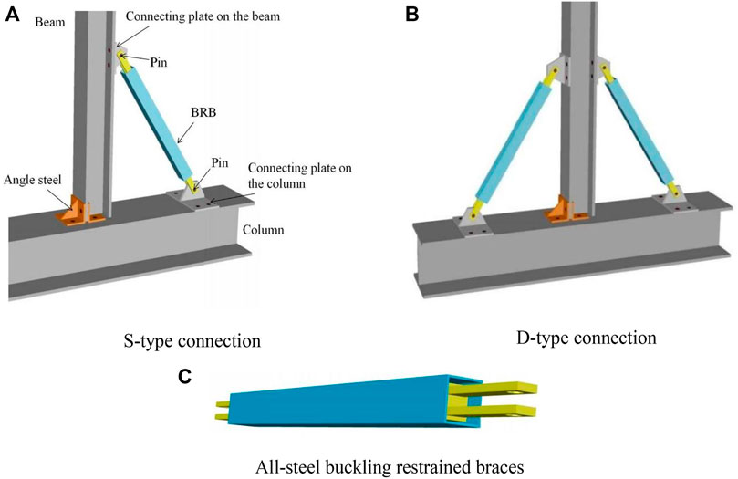
FIGURE 1. Construction of proposed beam-to-column connection.
Figure 2 shows the force transfer of the new connection system. Points A and C indicate that the connection between BRB and the flange of the column is connected by pins. Points D and E indicate that the connection between BRB and the flange of the beam is also connected by pins. When the beam end is acted by horizontal force Fb, the forces at each critical point of the connection are transmitted along the arrow direction. The forces at points D and E are balanced by the forces at points A and C. The axial load of the BRB is recorded as Ny. The yield of the connection system is defined only as the BRBs undergo plastic deformation, and the beam and column remain elastic.
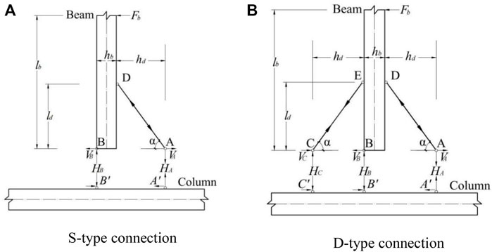
FIGURE 2. Force transfer models.
Yield load of S-type connection:
Where: lb—length of beam.
hb—height of beam
hd—distance between BRB lower end connecter and beam bottom end. α—Angle between BRB and column flange.
Yield load of D-type connection:
The ideal failure mode of the new connection system is that the BRB yields before the beam and column and uses its great hysteretic performance to absorb energy. When the connection reaches the ultimate displacement angle, the main components, such as beams and columns, do not yield. The deformation of the new connection system is mainly composed of the plastic deformation of the BRB. Among them, the BRB achieves the purpose of energy dissipation by yielding deformation of the inner core and restraining the inner core by the outer tube to prevent its buckling failure. It can be seen that the plastic deformation of BRB is mainly concentrated in the inner core; therefore, the connection rotation can be simplified into a geometric model, as shown in Figure 3.
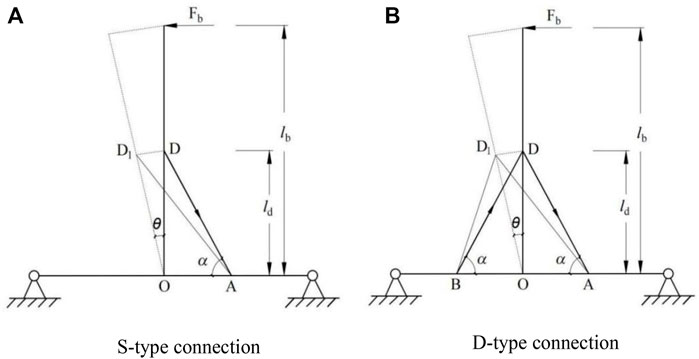
FIGURE 3. Structural deformation mechanism.
In the S-type connection, the stiffness, K1, provided by the deformation of the BRB can be obtained from the relationship between the beam end displacement and the deformation of a single BRB:
Where: l—length of BRB.
ld—distance between BRB upper connecter and beam bottom.
E—elastic modulus of BRB inner core.
A—sectional area of BRB inner core
θ—Rotation angle of beam.
In the D-type connection, the stiffness, K2, provided by the deformation of BRBs can be obtained from the relationship between the beam end displacement and the deformation of double BRBs:
To confirm the mechanical properties of the new connection system, quasi-static tests under cyclic loading were carried out. A total of two beam-column connection specimens were conducted. The specimens were T-connections composed of H-shaped steel beams, H-shaped steel columns, and BRBs. The column was H300 × 300×16 × 16, and the beam was H150 × 150×12 × 12. One side of the beam was connected to the column flange by angle steel. To facilitate installation and disassembly, the BRB was connected to the connecting plate on the beam-column flange with pins, and the connecting plate was connected to the beam-column flange with M20 high-strength bolts. This structure can efficiently achieve post-earthquake repair and adapt to the installation conditions of various BRBs by replacing different connecting plates. In order to ensure the force transmission of beam-column connections, stiffeners were set at the corresponding positions of beam-column flanges. Q345 grade steel was used for beam and column specimens, and Q235 grade steel was used for BRB specimens. Table 1 summarizes the mechanical properties of these steel materials.
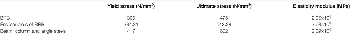
TABLE 1. Material properties.
The BRB was composed of a cruciform-section inner core, a round inner tube, a square outer tube, and end connectors. The form of double constraints of inner and outer tubes can better provide constraints for the inner core, preventing its buckling failure, which can improve the energy dissipation capacity of the brace. The detailed structure of the BRB is shown in Figures 4A–C. The inner core is placed in the round tube, the square tube is sleeved on the outermost layer, and the inner tube is fixed by drilling and welding four M16 screen bolts on the outer tube. Figures 4D–G show the connection and BRB dimensions.
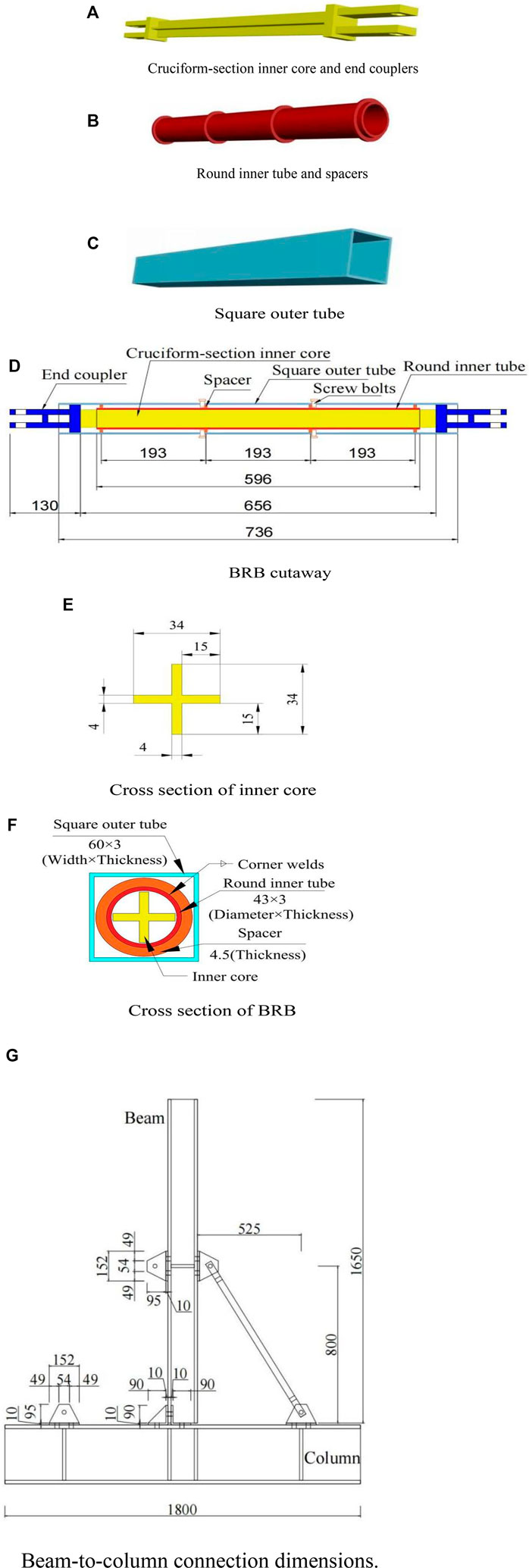
FIGURE 4. Connection system construction details. Quasi-static test device and measurement scheme.
In this test, a hydraulic actuator with a maximum loading pressure of 150 tons and a tensile force of 70 tons was selected for loading. Using a lying T beam-column frame, the actuator was loaded at the top right flange of the beam. The BRB was hinged with the beam-column frame through connecting plates and pins. The lower flange of the specimen column was connected to the hinge support through bolts, and the hinge support was fixed on the test ground beam to control the out-of-plane deformation of the specimen. The whole experimental device is shown in Figure 5A.
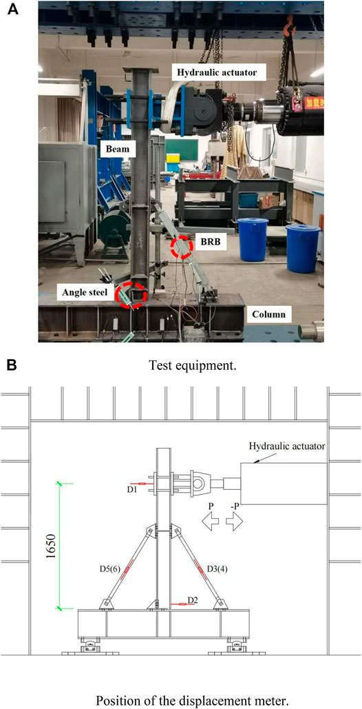
FIGURE 5. Test-setup.
The primary data measured in this test were beam end force, beam end displacement, brace deformation length, and brace axial strain. The layout scheme of the displacement meter is shown in Figure 5B. Among them, the displacement length of the brace was obtained by arranging a displacement meter with a range of ±25 mm. One end of the displacement meter was connected to the end connecter of the brace, and one end was placed on a fixed support (the support will never contact the experimental body during the experiment to avoid the shaking of the experimental body affecting its reading). The displacement meter was parallel to the brace as a whole, one at the front and one at the back (left displacement meters D5 and D6, right displacement meters D3 and D4). The deformation displacement of the brace was obtained by averaging the readings of two displacement meters to make it more accurate. The displacement and load at the beam end can be measured directly by the electro-hydraulic servo system. The displacement generated by the hydraulic actuator running to the left is defined as positive displacement and to the right as negative displacement. In order to analyze and verify the energy dissipation effect of BRB in the new connection, strain gauges were arranged on the inner core, inner tube, and outer tube of four sections (Figure 6).
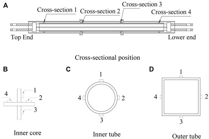
FIGURE 6. Position of strain gauges.
In this test, the quasi-static test of low cycle reciprocating cyclic loading was carried out by displacement control. Control displacement (δ) is the difference between the displacement at the top loading of the beam and the bottom of the beam. That is the difference between the horizontal displacement of the D1 and D2 displacement meters in Figure 5B. The interlayer displacement angles were 0.005, 0.01, 0.02, 0.03, and 0.04, which loaded twice, and the beam rotation angle (θ = δ/lb, lb) is the height from the bottom of the beam to the loading position. The test loading conditions are shown in Figure 7.
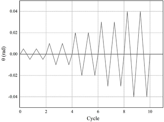
FIGURE 7. Loading protocol.
Figure 8 shows the load rotation angle hysteretic curve of S-type and D-type connections, where F is the horizontal load on the beam top, and θ is the corresponding beam rotation angle. As shown in Figure 8, the hysteretic curves of both specimens are spindle-shaped, indicating that they have a great energy absorption capacity and stable hysteretic performance. At the initial loading stage, the specimen is in the elastic stage, the change of load rotation angle is basically linear, and the area surrounded by the hysteresis loop is minimal. With the increase of working conditions, the hysteretic curve becomes full and shows great energy consumption characteristics because the inner core of the BRB yields. Due to the restraint of the inner and outer tubes, the inner core will continue to deform without buckling failure to absorb energy better. Under the same loading amplitude, the hysteretic curves of each cycle basically coincide, so it can be seen that the specimen has no strength degradation under cyclic load.
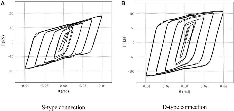
FIGURE 8. Hysteresis curve.
The hysteretic curve of the S-type has a slight load fluctuation but no significant influence on the overall hysteretic performance. This was caused by the friction between the inner core and the inner tube after compression deformation. At the same time, the sliding of the high-strength bolt after stress would also have a certain impact on the load stability. The hysteretic curve of the D-type is fuller than that of the S-connection, which shows that the structure of setting damping on both sides of the beam flange can make the new connection system have more substantial energy dissipation capacity.
The skeleton curves of the S-type and D-type connections are shown in Figure 9. According to the theoretical model above, the connection theoretical skeleton curve is drawn and compared with the test results (Table 2). The average error of the comparison is only 7.945%, indicating that the theoretical model has high accuracy. At the initial loading stage, the skeleton curve is essentially a straight line, and the specimen is in the elastic stage. When the specimen enters the yield stage, the slope of the skeleton curve decreases continuously, and the deformation develops faster than the load. According to the skeleton curves of the two specimens, under the same displacement, the negative load is slightly larger than the positive load, which is due to friction generated by contact with the inner tube wall after the compression deformation of the inner core of the BRB. Because there was an angle steel connection on the left side of the beam flange, the positive and negative forces of the D-type were also asymmetric, and the deformation of the left BRB was less than that of the right. It is worth noting that the yield load of the D-type is not twice that of the S type because the angle steels absorb part of the load. This is also taken into account in the theoretical yield load.
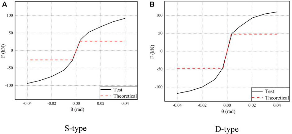
FIGURE 9. Experimental and theoretical skeleton curves.
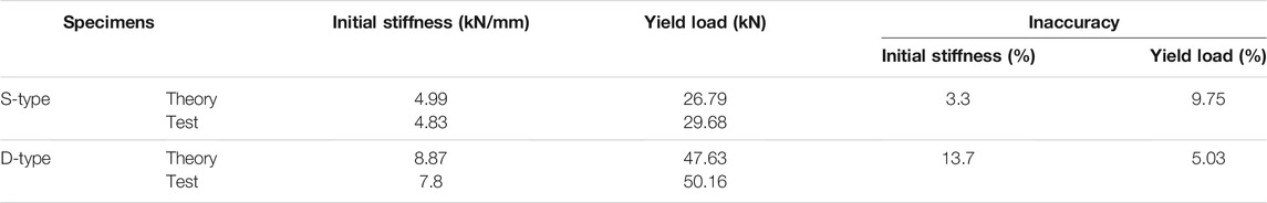
TABLE 2. Comparison between experimental result and analytical result.
After the quasi-static test of reciprocating loading, the beam and column members of the S-type and D-type connections remained elastic. Therefore, this section only analyzes the axial strain response of the BRB which is a energy dissipation element. Figure 10 shows the distribution proportion of the compressive strain of the BRB; the abscissa represents the rotation angle of the beam, and the ordinate represents the relative strain proportion of the inner core, round inner tube, and square outer tube under each working condition. All strain data were obtained from the average value measured by the strain gauge in Section 2 (Figure 6). When the rotation angle was within 0.00398, the inner cores of the three braces yielded. As shown in the figure, when the rotation angle of the two connections was 0.01, the strain of the inner core of the brace reached 90%, indicating that the brace still has stable plastic deformation ability after yield. When loading was continued, the inner core was continuously deformed and squeezed into the inner tube, so the strain proportion of the inner tube and the outer tube became larger. When the beam’s rotation angle reaches the maximum of 0.04, the total compressive strain of the inner tube and the outer tube did not exceed 25%. That is, the principal strains were concentrated in the inner core. It shows that the inner core, as the main load-bearing component, absorbs energy through deformation, which verifies the energy dissipation capacity of the BRB.
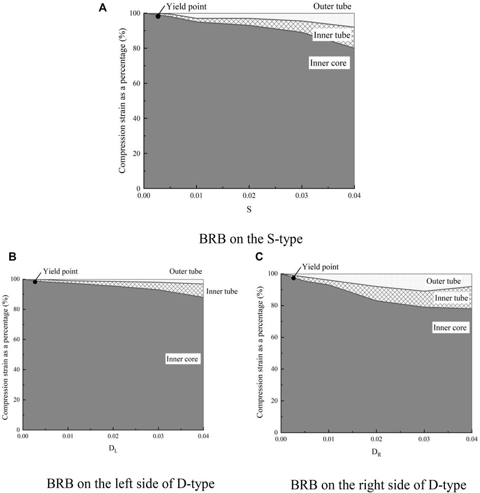
FIGURE 10. Compression strain distribution.
When comparing Figures 10B,C, it can be seen that in the D-type connection, the compression strain ratio of the inner and outer tubes of the left BRB is significantly less than that of the right BRB. The left angle’s presence causes the beam’s rotation point to be biased to the left, which makes the deformation of the right BRB larger than the left for the same beam rotation angle. Therefore, the BRBs on both sides of the connection will improve the connection’s energy dissipation capacity and ductility through mutual coupling and interaction rather than the superposition of two braces.
The energy dissipation capacity is an important index to evaluate the seismic performance of structural systems or specimens. In this paper, the energy dissipation capacity of the specimen is qualitatively studied through the total hysteretic energy dissipation index and equivalent viscous damping coefficient under each cycle condition.
The total hysteretic energy consumption is obtained by calculating the area surrounded by the hysteretic loop under each working condition (Figure 11). After comparing the total energy consumption of the S-type and D-type, it can be seen that the new connection system has a desirable dissipation performance, and the D-type has a stronger energy absorption capacity than the S-type. BRBs play a minor role in small deformations, which mainly enhances the stiffness of connections. When the deformation is large, it shows a stable energy dissipation effect until the end of loading.
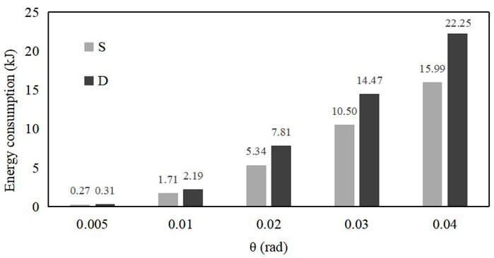
FIGURE 11. Specimens hysteresis energy dissipation-displacement curve.
Equivalent viscous damping coefficient (GB 50011-2010, 2010) can be determined based on
Where ED is the energy contained in the hysteresis loop under each displacement amplitude, ES1 is the area surrounded by the secant stiffness at the maximum positive displacement, and ES2 is the area surrounded by the secant stiffness at the maximum negative displacement. Calculations were made according to the data of the second cycle hysteretic curve under various working conditions.
Figure 12 shows that the equivalent viscous damping coefficient of the two specimens increases with the increase of displacement, indicating that the energy consumption level of the test piece increases with loading. The equivalent viscous damping coefficient of the S-type specimen before the rotation angle of 0.01 is greater than that of the D-type specimen, but the subsequent growth rate is much lower than that of the D-type specimen. At the same time, when θ is 0.02, he of the D-type specimen is greater than 0.4. When θ is 0.03, he of the S-type specimen is greater than 0.4. Therefore, it can be seen that the energy dissipation capacity of the D-type specimen is stronger and stabler than that of the S-type specimen. It also shows that the new connection system with new BRBs has a desirable energy dissipation performance.
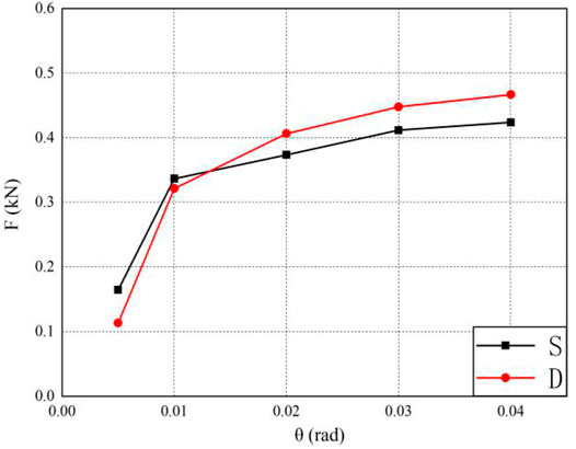
FIGURE 12. Equivalent viscous damping coefficient curve of the specimens.
During the specimen loading process, the connection stiffness gradually degrades with the increasing displacement, which can be expressed by the effective stiffness, based on ,
Fi is the load value of the loading peak point under the ith working condition, and xi is the displacement value of the loading peak point under the ith working condition.
The effective stiffness of the test piece is shown in Figure 13. Both curves decreased rapidly in the early stage, making them sharp and steep. In the later stage, the decline was slow, resulting in gradual and soft curves. It shows that the initial load is small, the BRB has little effect, and the stiffness degenerates quickly. In the later stage of loading, the inner core of the yielding brace enters the plastic energy dissipation stage under the constraints of the circular tube and the outer tube, and the effective stiffness of the connection decreases slowly and steadily. Through comparison, it can be seen that the effective stiffness of the D-type specimen under each working condition is higher than that of the S-type specimen, meaning that BRBs have an obvious effect on improving the stiffness of connections.

FIGURE 13. Comparison curves for effective stiffness of specimens.
In this paper, a new type of beam-to-column connection of steel structures with all-steel BRBs, a great deformation capacity, and is easy to repair after an earthquake is proposed. The BRB is an energy-dissipating element connected to the H-shaped steel beam and H-shaped steel column with pins. To verify the energy dissipation capacity of the connection system, quasi-static tests were carried out on the S-type and D-type connections. The key conclusions are noted below.
1 The new connection system has stable hysteretic performance and a high energy absorption capacity. The D-type’s energy dissipation performance is better than the S-type because of the proper arrangement of double BRBs.
2 The mechanical model used in this paper has high accuracy. The theoretical solutions of the initial stiffness and yield strength are in great agreement with the experimental results, which can be effectively used to evaluate the mechanical behavior of the new connection system.
3 In the cyclic loading test, when the displacement rotation angle is large, the plastic deformation was generated only in BRBs while the column and beam members remained elastic.
4 The energy dissipation capacity of the BRB is verified by analyzing the proportion of compressive strain of the inner core, inner tube, and outer tube in each BRB member. BRBs set on both sides of the connection will exert energy dissipation through mutual coupling; therefore, the mechanical properties of the D-type connections cannot be simply regarded as the superposition of two S-type connections.
5 This paper has verified that the proposed new connection system has a great energy dissipation capacity. Further studies are necessary for a more comprehensive assessment of the seismic performance of the structural system.
The original contributions presented in the study are included in the article/supplementary material further inquiries can be directed to the corresponding author.
JG: Conceptualization, writing—review and editing, funding acquisition JX: Data curation, writing—original draft preparation YX: Software, methodology BC: Validation, supervision DZ: Software, methodology XZ: Project administration, supervision YC: Funding acquisition, validation.
Author DZ is employed by Hang Xiao Steel Structure (HaiNan). Author XZ is employed by Jiangsu Taile Damping Technology Co., Ltd.
The remaining authors declare that the research was conducted in the absence of any commercial or financial relationships that could be construed as a potential conflict of interest.
All claims expressed in this article are solely those of the authors and do not necessarily represent those of their affiliated organizations, or those of the publisher, the editors and the reviewers. Any product that may be evaluated in this article, or claim that may be made by its manufacturer, is not guaranteed or endorsed by the publisher.
The authors gratefully acknowledge the financial supports from Engineering Research Center of Nuclear Technology Application foundation (East China University of Technology), Ministry of Education (HJSJYB20168, HJSJYB 201510) and Education Department of Jiangxi Province (GJJ180373).
Alexander, J., Mateus, S., Tagawa, H., and Chen, X. C. (2019). Buckling-restrained Brace Using Round Steel Bar Cores Restrained by Inner Round Steel Tubes and Outer Square Steel Tubes [J]. Eng. Structures 197 (109379), 1–15. doi:10.1016/j.engstruct.2019.109379
Byakuno, Y., Koetaka, Y., and Inoue, K. (2004). Earthquake Response Analysis of Steel Frames with Bolted Beam-To-Column Connections Using Buckling-Restrained Knee Brace Dampers. Nihon Kenchiku Gakkai Kozokei Ronbunshu. Proc. Struct. Eng. Architectural Inst. Jpn 69, 219–226. (in Japanese). doi:10.3130/aijs.69.219
Chen, B., Jia, B., Wen, M., and Li, X. (2021d). Seismic Performance and Strengthening of Purlin Roof Structures Using a Novel Damping-Limit Device. Front. Mater 8, 722018. doi:10.3389/fmats.2021.722018
Chen, B. K., Du, Y. J., Shi, Y., and Fan, L. (2021b). Seismic Analysis of Isolated Continuous Bridge Considering Influence of Seawater and Site Condition [J]. Shock and Vibration 2021, 1–17. doi:10.1155/2021/7599715
Chen, B. K., Wang, D. S., Chen, S. L., and Hu, S. C. (2021a). Influence of Site Factors on Offshore Ground Motions Observed Results and Numerical Simulation [J]. Soil Dyn. Earthquake Eng 145, 106729. doi:10.1016/j.soildyn.2021.106729
Chen, Y. A., Chen, C. A., and Chen, C. B. (2021c). Study on Seismic Performance of Prefabricated Self-Centering Beam to Column Rotation Friction Energy Dissipation Connection [J]. Eng. Structures 241, 112136. doi:10.1016/j.engstruct.2021.112136
Chou, S. S., Inoue, K., Koetaka, Y. J., and Byakuno, Y. (2004). Seismic Design and Dnamic Analysis of Steel Frames with Bolted Beam-To-Column Connection Using Buckling-Restrained Knee Brace Dampers [C]. Proc. Struct. Eng. Architectural Inst. Jpn 11, 42. (in Japanese). doi:10.11273/jssc1994.11.42_63
Erfani, S., Asnafi, A. A., and Goudarzi, A. (2016). Connection of I-Beam to Box-Column by a Short Stub Beam. J. Constructional Steel Res 127, 136–150. doi:10.1016/j.jcsr.2016.07.025
GB 50011—2010 (2010). Code for Seismic Design of Buildings [S]. China: China Architecture and Building Press.
Guo, Y. L., Tong, J. Z., and Zhou, P. (2016). Pesearch Progress of Buckling Restrained Braces Types, Design Methods and Applications [J]. Eng. Mech 33 (09), 1–14. doi:10.6052/j.issn.1000-4750.2016.04.ST01
Hamid, H., and Shahrokh, M. (2017). Conceptual Numerical Investigation of All-Steel Tube-In-Tube Buckling Restrained Braces [J]. J. Constructional Steel Res 139, 220–235. doi:10.1016/j.jcsr.2017.09.022
Han, S. W., Moon, K. H., and Hwang, S. H. (2011). Rotation Capacities of Reduced Beam Section with Bolted Web (RBS-B) Connections [J]. J. Constructional Steel Res. 70 (1), 256–263. doi:10.1016/j.jcsr.2011.09.001
Koetaka, Y., Chusilp, P., Zhang, Z., Ando, M., Suita, K., Inoue, K., et al. (2005). Mechanical Property of Beam-To-Column Moment Connection with Hysteretic Dampers for Column Weak axis. Eng. Structures 27 (1), 109–117. doi:10.1016/j.engstruct.2004.09.002
Li, D., Wu, C., Zhou, Y., Luo, W., and Lie, W. (2021). A Precast Beam-Column Connection Using Metallic Damper as Connector Experiment and Application. J. Constructional Steel Res 181, 106628. doi:10.1016/j.jcsr.2021.106628
Li, G. Q., Sun, F. F., and Shen, Z. Y. (1998). Fracture Behavior of Steel Frame Beam Column Welded Connections under strong Earthquakes [J]. J. building structures. 19 (04), 19–28. doi:10.14006/j.jzjgxb.1998.04.003
Li, H.-N., Qu, C., Huo, L., and Nagarajaiah., S. (2016). Equivalent Bilinear Elastic Single Degree of freedom System of Multi-Degree of freedom Structure with Negative Stiffness. J. Sound Vibration 365, 1–14. doi:10.1016/j.jsv.2015.11.005
Liu, M. (2008). Study on New Lead Dampers and Seismic Behavior of Prestress Assembling Beam-Column Connections [D]. China: Beijing University of technology.
Liu, X. C., Yang, Z. W., Wang, H. X., Zhang, A. L., Pu, S. H., Chai, S. T., et al. (2017). Seismic Performance of H-Section Beam to HSS Column Connection in Prefabricated Structures. J. Constructional Steel Res 138, 1–16. doi:10.1016/j.jcsr.2017.06.029
Mander, T. J., Rodgers, G. W., Chase, J. G., Mander, J. B., MacRae, G. A., and Dhakal, R. P. (2009). Damage Avoidance Design Steel Beam-Column Moment Connection Using High-Force-To-Volume Dissipators. J. Struct. Eng 135 (11), 1390–1397. doi:10.1061/(asce)st.1943-541x.0000065
Mohamad, H. M., and Seyed, M. Z. (2020). Analytical and Numerical Studies on Reducing Lateral Restraints in Conventional and All Steel Buckling Restrained Braces [J]. J. Building Eng 32 (7), 101513. doi:10.1016/j.jobe.2020.101513
Oh, S.-H., Kim, Y.-J., and Ryu, H.-S. (2009). Seismic Performance of Steel Structures with Slit Dampers. Eng. Structures 31 (9), 1997–2008. doi:10.1016/j.engstruct.2009.03.003
Qu, C., Li, H.-N., Huo, L., and Yi, T.-H. (2017). Optimum Value of Negative Stiffness and Additional Damping in Civil Structures. J. Struct. Eng 143 (8), 04017068. doi:10.1061/(asce)st.1943-541x.0001805
Sherven, M., and Maryam, T. (2012). Numerical Study of Slotted-Web-Reduced-Flange Moment Connection [J]. J. Constructional Steel Res. 69 (1), 1–7. doi:10.1016/j.jcsr.2011.06.003
Shi, G., Chen, X., and Wang, D. (2017). Experimental Study of Ultra-large Capacity End-Plate Joints. J. Constructional Steel Res 128, 354–361. doi:10.1016/j.jcsr.2016.09.001
Suita, K., Inoue, K., Takeuchi, I., and Uno, N. (2003). Mechanical Behavior of Bolted Beam-To-Column Connections with Buckling-Restrained Knee Brace Dampers. Nihon Kenchiku Gakkai Kozokei Ronbunshu. Proc. Struct. Eng. Architectural Inst. Jpn 68, 153–160. (in Japanese). doi:10.3130/aijs.68.153_4
Terashima, Y., Byakuno, Y., Taga, K., and Inoue, K. (2007). Earthquake Response of High-Rise Steel Frames with Bolted Beam-To-Column Connections Using Buckling-Restrained Knee Brace Dampers [C]. Proc. Struct. Eng. Architectural Inst. Jpn 14, 55. (in Japanese). doi:10.11273/jssc1994.14.55_73
Tomokazu, Y., and Masamichi, O. (2004). “Hinge Mechanism of Moment Resisting Steel Frame Using Bolted Frictional Slipping Damper [C],” in Canada 13th World Conference on Earthquake Engineering, Canada, 2004, 158–164.
Tsavdaridis, K. D., and D’Mello, C. (2012). Vierendeel Bending Study of Perforated Steel Beams with Various Novel Web Opening Shapes through Nonlinear Finite-Element Analyses. J. Struct. Eng 138 (10), 1214–1230. doi:10.1061/(asce)st.1943-541x.0000562
Wu, C. X., Li, D. B., Deng, X. S., Cheng, Y., and Xin, X. (2020). Experimental Study on Precast concrete Moment-Resisting Frame System with Sector lead Viscoelastic Dampers [J]. Struct. Control. Health Monit 33 (6), 42–49. doi:10.14006/j.jzjgxb.2012.06.015
Wu, Z. P., Hu, D. Z., Chen, X. Y., and Nie, C. R. (2020). Mechanical Behavior of Steel Bar Buckling Restrained Braces [J]. J. Building Structures 41, 163–171. (in Chinese).
Keywords: steel, beam-to-column connection, energy dissipation, buckling-restrained brace, quasi-static test
Citation: Gao J, Xi J, Xu Y, Chen B, Zhao D, Zhao X and Chang Y (2022) Mechanical Property of Beam-to-Column Connection of Steel Structures With All-Steel Buckling-Restrained Braces. Front. Mater. 8:821299. doi: 10.3389/fmats.2021.821299
Received: 24 November 2021; Accepted: 13 December 2021;
Published: 10 January 2022.
Edited by:
Zhicheng Yang, Zhongkai University of Agriculture and Engineering, ChinaReviewed by:
Liang Cao, Hunan University, ChinaCopyright © 2022 Gao, Xi, Xu, Chen, Zhao, Zhao and Chang. This is an open-access article distributed under the terms of the Creative Commons Attribution License (CC BY). The use, distribution or reproduction in other forums is permitted, provided the original author(s) and the copyright owner(s) are credited and that the original publication in this journal is cited, in accordance with accepted academic practice. No use, distribution or reproduction is permitted which does not comply with these terms.
*Correspondence: Jinhe Gao, amhnYW9AZWN1dC5lZHUuY24=
Disclaimer: All claims expressed in this article are solely those of the authors and do not necessarily represent those of their affiliated organizations, or those of the publisher, the editors and the reviewers. Any product that may be evaluated in this article or claim that may be made by its manufacturer is not guaranteed or endorsed by the publisher.
Research integrity at Frontiers
Learn more about the work of our research integrity team to safeguard the quality of each article we publish.