
94% of researchers rate our articles as excellent or good
Learn more about the work of our research integrity team to safeguard the quality of each article we publish.
Find out more
ORIGINAL RESEARCH article
Front. Mater., 07 January 2022
Sec. Environmental Degradation of Materials
Volume 8 - 2021 | https://doi.org/10.3389/fmats.2021.820721
This article is part of the Research TopicAdvances in Materials Toward Anti-Corrosion and Anti-BiofoulingsView all 12 articles
 Jian Wang1,2,3
 Binbin Zhang1,2,4
 Weichen Xu1,2,4*
 Jie Zhang1,2,4*Lihui Yang1,2,4Zhongbo Peng3Baorong Hou1,2,4
Rail foot covered by a fastener will suffer from crevice corrosion, leading to thinning and localized attack of crevice interior posing a risk of failure. This work investigated crevice corrosion behavior of a typical pearlitic high-speed rail steel U75V, focusing for the first time on the effect of pearlitic microstructure refinement achieved by heat treatment with different cooling rates 2, 5, and 10°C/s. Under anodic polarization, localized dissolved spots presented on the as-received sample, where crevice corrosion mostly initiated from. For cooling rates 2 and 5°C/s, localized dissolved spots were also observed but crevice corrosion was mostly presented as general corrosion instead of from local spots, ascribed to enhanced tendency of uniform dissolution due to microstructure refinement and homogenization. For cooling rate 10°C/s, crevice corrosion expanded flocculently, ascribed to preferential dissolution of pearlitic nodules with entangled cementite due to over refinement. Crevice corrosion was obviously accelerated by microstructure refinement. Cooling rates 5 and 10°C/s led to the fastest and slowest expansion of the corroded area, respectively, while the corrosion depth was just the opposite based on the same amount of metal loss. This work provides important information regarding the effect of pearlitic microstructure refinement on crevice corrosion and introduces a facile method for in situ monitoring of crevice corrosion.
Rapid development of the high-speed railway industry requires high reliability and durability of materials. Wear, contact–impact, fatigue (or rolling contact fatigue, i.e., RCF), and corrosion are the main reasons for material degradation in rail tracks (Hernandez et al., 2007; Shurpali et al., 2012; Hernandez-Valle et al., 2013; Shariff et al., 2013; Safa et al., 2015; Zhao et al., 2015; Yazici and Yilmaz, 2018; Liu et al., 2019). Among these issues, corrosion attracts far less attention than the others while its damage is no less (Xu et al., 2021). This is because damage of materials caused by corrosion is unobservable from the beginning, but corrosion, especially localized corrosion, is usually an important precursor for accident or failure (Hill and Lillard, 2006; Li et al., 2017). Corrosion of rail tracks induces huge economic loss, and it has been reported that direct cost resulted from rail track corrosion (railcar excluded), including replacement of corroded components, maintenance regarding corrosion mitigation, and application of corrosion protection technologies, was 18.88 billion RMB (Hou et al., 2017).
Corrosion occurred on the large surface of rails (e.g., on rail head, where wear and contact–impact are much more severe) is not crucial since it tends to develop into general corrosion instead of growing deep (Xu et al., 2021), and frequent contact between the rail and wheel inhibits the formation of an electrolyte layer as a precursor of localized corrosion. However, severe corrosion problems very often take place near the rail base and rail foot, resulting in thinning of specific section and instability of rail, thus inducing a potential risk of displacement, large stress, or even severe engineering failure (Xu et al., 2021). Due to the special structure between the fastener system and rail foot section, the crevice corrosion issue on the rail track has been reported by Panda et al. (2008), Panda et al. (2009) and has been recently investigated in details by the authors of this work, especially under conditions of varying gap size (Xu et al., 2022).
Pearlitic steels are widely applied as rail track steels due to their excellent mechanical properties, while the corrosion issue was usually overlooked (Hernandez et al., 2007). Microstructures strongly influence electrochemical dissolution behaviors (Haisch et al., 2002). The microstructure of various carbon steels has been studied, and the close relationship between pearlitic lamellar structure and initiation of localized corrosion was proposed (Clover et al., 2005), mostly stemmed from different electrochemical potentials between ferrite and cementite leading to galvanic coupling (Panda et al., 2008; Katiyar et al., 2018).
The microstructure of pearlite, especially interlamellar spacing, is closely related to corrosion resistance (Toribio and Ovejero, 2001; Katiyar et al., 2018; Wu et al., 2020). Ren et al. (2012) compared two kinds of pearlitic steels and found that smaller interlamellar spacing and more uniform structure resulted in higher resistance to atmospheric corrosion. Refinement of microstructure and the decrease of interlamellar spacing resulted in an improvement of polarization resistance and mechanical properties (toughness, strength, and hardness) and also a decrease of the corrosion rate (Panda et al., 2008; Katiyar et al., 2018), but further refinement led to entanglement of cementite lamellae and an increase of the corrosion rate (Katiyar et al., 2018). Ren (2012) also reported an increase of corrosion resistance due to the decrease of interlamellar spacing of pearlitic steels, and the dispersion degree (uniformity) of the interlamellar spacing was found to be inversely related to corrosion resistance. It seems that the lamellar structure of pearlite is often the weakness regarding corrosion (coarser structure generally resulted in lower localized corrosion resistance) (Al-Rubaiey et al., 2013). However, the appearance of pearlite was recently reported to act as a cathode and help suppress corrosion of a multi-phase rail steel (Neetu et al., 2021). Therefore, the effect of the pearlitic phase on corrosion depends on different factors, and a consistent conclusion cannot be simply drawn.
A study on crevice corrosion of pearlitic steel is very few. Preferential dissolution of pearlite nodules with larger interlamellar spacing between ferrite and cementite has been reported to initiate crevice corrosion and induce a corrosion defect with the sharp tip at the crevice interior, posing a risk of cracking (Xu et al., 2022). The boundary of ferrite and cementite has been observed to dissolve preferentially, resulting in threatening crack-like trenches (Murase et al., 2021). Moreover, localized (crevice) corrosion coupled with stress can potentially lead to cracking (Hernandez et al., 2009; Li et al., 2017; Li et al., 2020). Crevice corrosion of pearlitic steel was observed to start from oval-like spots ascribed to preferential dissolution of specific pearlitic nodules (Xu et al., 2022), while the effect of interlamellar spacing on the initiation and development of crevice corrosion of pearlitic steels is still unclear.
In this work, the effect of interlamellar spacing between ferrite and cementite lamellae on crevice corrosion behaviors of typical pearlitic high-speed rail track steel U75V has been investigated for the first time. Since crevice corrosion was usually difficult to be visualized, a self-made monitoring system was applied to observe initiation and development of crevice corrosion in situ under a transparent glass crevice former.
U75V high-speed rail steel was cut into discs (diameter 6 mm) from the rail foot section. The chemical composition of as-received U75V steel is listed in Table 1. Variation of interlamellar spacing was obtained by heat treatment with different cooling processes. Heat treatments were performed by using a Gleeble-3500 thermal mechanical simulator (Dynamic Systems Inc.). U75V discs were heated from room temperature to 950°C in 5°C/s and kept for 10 min and then cooled to below 200°C at different cooling rates 2, 5, and 10°C/s.

TABLE 1. Chemical composition (wt%) of U75V steel (the balance is Fe).
After heat treatment, the disc surface was mirror polished until scratches were not observable via an optical microscope. The surface was etched by 4% nital for 4–6 s, washed with ethanol, and air-dried for further microstructural analysis.
U75V discs, after heat treatment, were welded with the electric cable and embedded in an epoxy resin with the exposed surface area of 0.283 cm2. The surface was ground with SiC sand papers 600, 1,000, 1,500, 2,000, and 3,000 successively. Both crevice-free and crevice corrosion measurements were carried out.
For crevice-free tests, the samples were immersed in 0.1 M NaCl after grinding. Open circuit potential was always measured first until its change with time was less than 3 mV/min (ΔOCP/Δt < 3 mV/min, ca. 40 min from the start of immersion), and then polarization tests were carried out. The electrochemical workstation Ivium Vertex.C.EIS (Ivium Technologies BV, The Netherlands) was used for all electrochemical tests. The reference electrode was a saturated calomel electrode (SCE), and the counter electrode was a platinum foil (2 cm × 2 cm) connected to a Teflon rod.
For crevice corrosion investigation, a self-designed device was applied for electrochemical tests and in situ monitoring of corrosion morphology development. A piece of transparent glass was used as a crevice former, fixed in a frame with grooves, and connected to a Z-axis sliding stage (with a micrometer) as a crevice gap size controller, so that the gap size can be adjusted as required. The combination of electrochemical methods and real-time corresponding images is important, so this device incorporated an optical system with a vertically placed Navitar microscope, coupled using a CCD camera connected to a computer. The lens was above the surface of the working electrode (working distance ca. 7 cm) and fixed on a stage which allowed movement in X and Y directions. A ring illuminator was fixed around the lens. The magnification was 50X–400X. A schematic diagram illustrating this device is shown in Figure 1. The disc samples were immersed in 0.1 M NaCl after grinding with a 50 µm crevice gap. Considering surface roughness and machining tolerance regarding the contact surface between the rail foot and fastener (Xu et al., 2021), a gap size of 50 µm is regarded as a reasonable value in this work. Similarly, open circuit potential was measured to achieve stable OCP (ΔOCP/Δt < 3 mV/min, ca. 50 min from the start of immersion), and polarization tests were carried out afterward when required.
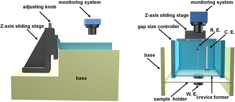
FIGURE 1. Schematic diagram of the self-designed in situ monitoring device.
Besides the self-designed device, a scanning electron microscope (HITACHI Regulus 8100) was applied for corrosion morphology investigation after etching or electrochemical measurements. A 3D measuring laser scanning microscope (Olympus LEXT OLS5000) was applied after electrochemical tests, and LEXT analysis software was used for comparison of the surface profile.
The SEM micrographs of the etched surface of disc samples after heat treatment are shown in Figure 2. The interlamellar spacing was noticeably decreased with the increasing cooling rate, except that it was not as remarkable if 2 and 5°C/s are compared. Furthermore, the thickness of both ferrite lamella and cementite lamella was decreased after heat treatment and decreased with the increasing cooling rate.
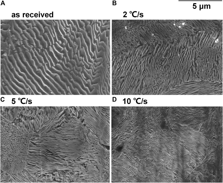
FIGURE 2. SEM micrographs of the etched surface of the (A) as-received sample and the samples after heat treatment with cooling rates (B) 2°C/s, (C) 5°C/s, and (D) 10°C/s.
After OCP was stabilized under free immersion conditions, four different samples were dynamically polarized in 0.1 M NaCl without crevice (anodic and cathodic polarizations were carried out separately; scan rate 0.1667 mV/s). From cathodic polarization curves (Figure 3A), the difference between four samples was not obvious except the difference on OCP, indicating similar behavior of oxygen reduction regardless of microstructure. From anodic polarization curves, there were noticeable differences in the weak polarization region (presenting a “shoulder” for AR, 2, and 10°C/s, while 5°C/s was less obvious due to its higher OCP) representing the early stage of anodic dissolution. According to the classic Evans diagram, when the cathodic reaction remains the same, OCP increases with the suppressed anodic reaction. Therefore, the anodic dissolution rate of samples related to the cooling rate 2 and 5°C/s in the early stage was lower than that of the as-received sample, while that for 10°C/s was the highest. This well agrees to Katiyar et al. (2018) who reported that refined microstructure was helpful on decreasing the corrosion rate, but further refinement may lead to accelerated corrosion again. The development of corrosion morphology was very quick due to the absence of inhibition of metal ions diffusion, and the surface quickly turned dark for all four samples, making it difficult for taking successive macrographs of the changing surface.
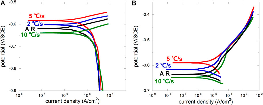
FIGURE 3. Cathodic (A) and anodic (B) polarization curves of the as-received sample (AR) and the samples after heat treatment with cooling rates 2°C/s, 5°C/s, and 10°C/s.
Generally, the ferrite lamella acts anodically, and the cementite lamella acts cathodically (Murase et al., 2021). Interlamellar spacing distribution was usually scattered for the as-received sample (Ren, 2012), and corrosion usually initiated from pearlitic nodules with larger interlamellar spacing and larger area of ferrite lamellae (more local ferrite implies higher possibility to be locally dissolved under both free immersion and anodic polarization conditions) (Xu et al., 2022). After microstructure refinement, interlamellar spacing distribution tended to be homogenized, decreasing the amount of potential anodic initiation sites, and thus the amount of pearlitic nodules contributing to the anodic current would be less, leading to increased OCP according to the Evans diagram. However, the over-high cooling rate may lead to entanglement of the cementite lamella (Katiyar et al., 2018), resulting in more disordered microstructure and more potential anodic initiation site. The cooling rate 10°C/s may be the case, raising the anodic branch and decreasing OCP according to the Evans diagram. This is further discussed regarding crevice corrosion behaviors in following sections.
The samples were anodically polarized in 0.1 M NaCl at a potential of 0.15 V vs. OCP with a 50 µm crevice gap after OCP stabilized. The plot of anodic current density vs. time is shown in Figure 4A, and the calculated electric charge (linearly representing metal loss) is shown in Figure 4B. Heat treatment obviously promoted the anodic current for crevice corrosion, especially after the cooling rate 5°C/s, while cooling rates 2 and 10°C/s were similar, consistently higher than that of the as-received sample.
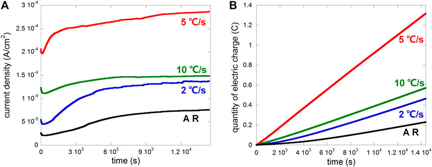
FIGURE 4. Plots of (A) current density vs. time and (B) electric charge vs. time of different samples (AR, i.e., as-received, and samples after heat treatment with cooling rates 2°C/s, 5°C/s, and 10°C/s) anodically polarized at 0.15 V vs. OCP in 0.1 M NaCl with a 50 µm crevice gap.
The macrographs of the as-received sample and after heat treatment with cooling rates 2, 5, and 10°C/s, taken during the anodic polarization process shown in Figure 4 using a self-designed in situ monitoring device (see Figure 1), are presented in Figures 5–8 respectively, with some local sites compared. 0 h means the start point of anodic polarization after free immersion (stable OCP was achieved).
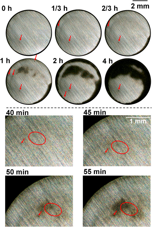
FIGURE 5. Macrographs of the surface of the as-received sample presenting crevice corrosion development at 0.15 V vs. OCP in 0.1 M NaCl, taken by the self-designed device (lower part shows upper left of the surface).
For the as-received sample (Figure 5), there were only a few spots that were preferentially dissolved at the end of free immersion (0 h). From the start of anodic polarization, more spots were gradually observed, which can be seen in the local sites presented in the lower part of Figure 5 (showing upper left of the sample surface), and these spots gradually developed into an enlarged dissolving area turning dark. This agrees to the previous work of the authors reporting the oval-like spots as initiation sites of crevice corrosion (Xu et al., 2022). There were corroded areas at the edge which was common for crevice corrosion because the diffusion of metal ions from the edge of crevice is the most readily. However, it is clearly noticed that some preferentially dissolved sites as shown in the lower part of Figure 5 were neither at the edge nor at the center, but at some area between the edge and center, which was suggested to be ascribed to the combination effect of interfacial potential and local chloride and/or proton accumulation (Xu et al., 2022). In the end of polarization (4 h), coalescence of different dark areas took place, and some part was still not corroded.
For the sample after heat treatment with the cooling rate 2°C/s (Figure 6), a few preferentially dissolved spots were observed and expanded slightly during polarization (see the lower part of Figure 6 showing bottom left of the sample surface), but newly formed spots during polarization was not clearly noticed. However, unlike the as-received sample, most of the dissolved area was not from these local spots, but from general corrosion on the relatively larger area (clearly shown on the macrograph taken at 1/3 h in the area marked by dashed red line), which turned light first and then dark. This area was also between the edge and center and coalesced with the edge area at the end.
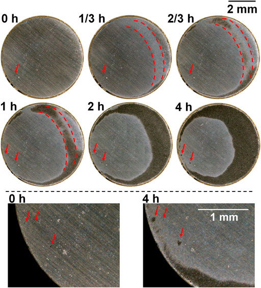
FIGURE 6. Macrographs of the surface of the sample after heat treatment with the cooling rate 2°C/s presenting crevice corrosion development at 0.15 V vs. OCP in 0.1 M NaCl, taken by the self-designed device (lower part shows bottom left of the surface).
For the sample after heat treatment with the cooling rate 5°C/s (Figure 7), preferentially dissolved spots were observed to be more than those observed in 2°C/s (Figure 6). The size of these spots did not grow noticeably till the end of anodic polarization, except that the periphery turned dark when the general corrosion area was about to cover the spots (see the lower part of Figure 7 showing bottom left of the sample surface). Instead, the development of crevice corrosion was mainly based on general corrosion, and some preferentially dissolved spots presented at the end of free immersion (Figure 7, 0 h, marked with red arrows) were still observable at 1 h, although the dark-dissolved area already covered these spots, indicating small dissolved depth of general corrosion. After 2 h, the whole surface was totally dissolved, which was obviously faster than the other samples, also proved by metal loss shown in Figure 4B. In addition, a bubble was observed after 2/3 h which was believed to be hydrogen gas since the crevice interior was already acidified and interfacial potential should allow its formation.
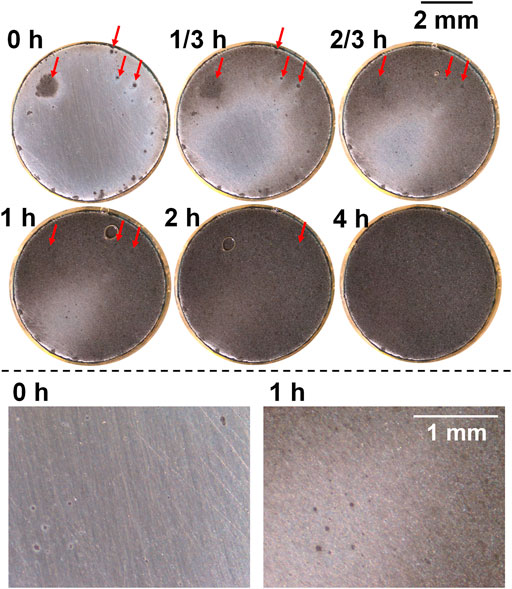
FIGURE 7. Macrographs of the surface of the sample after heat treatment with cooling rate 5°C/s presenting crevice corrosion development at 0.15 V vs. OCP in 0.1 M NaCl, taken by the self-designed device (lower part shows bottom left of surface).
For the sample after heat treatment with the cooling rate 10°C/s (Figure 8), preferentially dissolved spots were also observed, especially near the edge, and did not grow noticeably during polarization (see the lower part of Figure 8 showing bottom left and right of the sample surface). In addition, newly formed spots were not observed during polarization. The dissolution behavior was totally different from that of the other samples. The dissolved area was neither initiated from formerly dissolved spots (Figure 5) nor like general corrosion (Figures 6, 7); instead, it expanded from the edge to center flocculently (or reticularly).
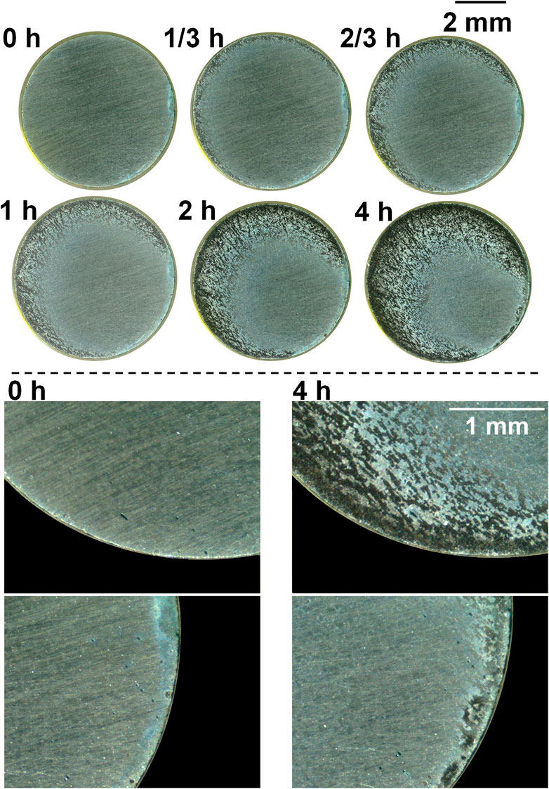
FIGURE 8. Macrographs of the surface of the sample after heat treatment with the cooling rate 10°C/s presenting crevice corrosion development at 0.15 V vs. OCP in 0.1 M NaCl, taken by the self-designed device (lower part shows bottom left and right of the surface).
Crevice corrosion behaviors of the four samples described previously under free immersion conditions were similar, presented with preferentially dissolved local sites, but differed noticeably under anodic polarization conditions. The tendency of general corrosion within crevice for samples after heat treatment was largely due to the refinement of microstructure. Dissolution of cementite is a kinetic process, and its dissolution rate is much lower than that of ferrite under anodic polarization conditions (Xu et al., 2015; Xu et al., 2017). When the interlamellar spacing was large (as-received sample), preferentially dissolved ferrite was very likely to act as a local site for corrosion initiation, and dissolved ferrite was separated by adjacent cementite. If the interlamellar spacing was decreased, accompanied with thickness decrease of both ferrite and cementite lamellae, preferentially dissolved ferrite lamellae were more easily to coalesce because the distance between the ferrite lamella was decreased and thinner cementite lamellae were more easily to detach. Therefore, general corrosion more readily took place for refined microstructure.
Micrographs of some typical local sites after identical anodic polarization tests (crevice gap 50 µm) were obtained by SEM to further investigate crevice corrosion behaviors of different samples. During the expansion of the creviced area, there were basically three areas according to the macrographs shown previously, i.e., fully dissolved area (appeared dark), non-corroded area, and the boundary between the two (presented as light color before turning dark, clear in Figures 6, 7). Therefore, SEM images of the fully dissolved area and boundary area of samples after heat treatment with cooling rates 2 and 5°C/s are shown in Figure 9. Figure 9A (fully dissolved area for 2°C/s) clearly shows the cementite skeleton due to preferential dissolution of ferrite. In the boundary area (Figure 9B), preferential dissolution of ferrite can also be observed but not as clear as Figure 9A; in addition, the scratches due to grinding still appear which is not presented in Figure 9A. Therefore, the generalized corrosion for 2°C/s was still based on preferential dissolution of ferrite. In comparison, Figure 9C (fully dissolved area for 5°C/s) does not show the typical pattern of the cementite skeleton but only some elongated cavity (ferrite lamella dissolution), and the scratches due to grinding can still be seen. The boundary area (Figure 9D) also does not show the typical pattern of the cementite skeleton. Therefore, the dissolution depth of 5°C/s was generally less than that of 2°C/s, although the expansion rate of the dissolved area (dark area) for 5°C/s was obviously higher than that of other samples (Figures 5–8). This is related to the observation that those dark spots formed during free immersion can still be seen even after the expanding corroded area crossing them (Figure 7, 1 h). The appearance of dark color on the dissolved area (observed in macrographs) was mainly due to cementite, either detached from the surface or remained as a skeleton, which has been reported before on localized corrosion of industrial pure iron (Xu et al., 2017) and carbon steel (Xu et al., 2019).
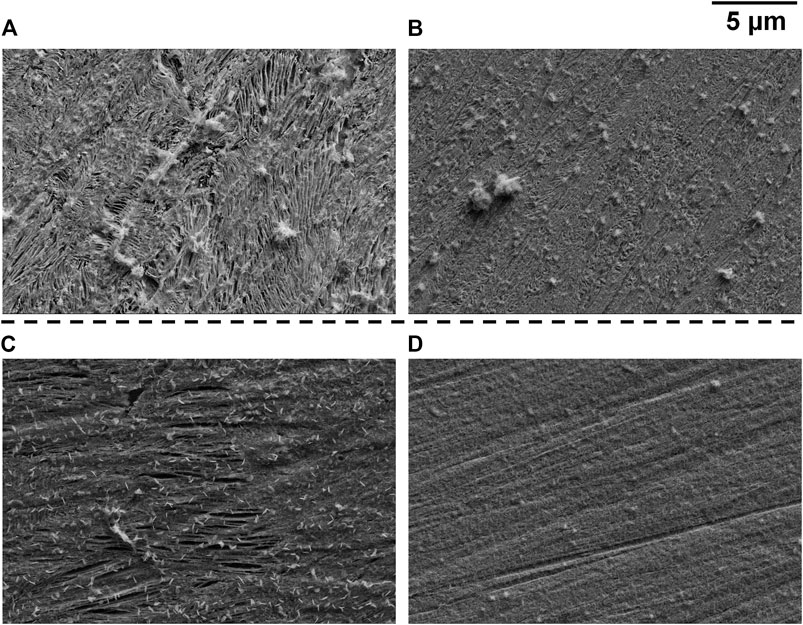
FIGURE 9. SEM micrographs taken on samples after heat treatment with cooling rates 2°C/s [(A) fully dissolved/dark area; (B) boundary area] and 5°C/s [(C) fully dissolved/dark area; (D) boundary area].
Figure 10 shows SEM images of the sample after heat treatment with the cooling rate 10°C/s. The flocculent dissolution behavior described regarding Figure 8 is more clearly presented in Figure 10A. Corrosion depth was different on the surface leading to different heights. The higher part shows some elongated cavities which was probably due to ferrite dissolution, and scratches due to grinding can still be seen. In comparison, the lower part shows the cementite skeleton where scratches disappeared (Figure 10B). It has been suggested by Katiyar et al. (2018) that the over-high cooling rate of heat treatment on pearlitic steel may lead to entanglement of cementite lamellae (typical of quasi-pearlitic structure) which decreases polarization resistance. It agrees with our study, and the entanglement was observed in Figure 10C. This kind of entanglement may also lead to connection of different cementite lamellae separating ferrite, which is a type of less-ordered microstructure than that of typical pearlite, forming a “big cathode and small anode” in certain local sites. The pearlitic nodules with more entangled cementite lamella were preferentially dissolved while the less entangled remained, resulting in the special flocculent corrosion pattern. A similar phenomenon was also observed on the etched surface as shown in Figure 10D, where dissolved and less-dissolved areas are clearly presented. Entanglement of the cementite lamella is noticeable, especially near the boundary of dissolved and less-dissolved areas (Figure 10E).
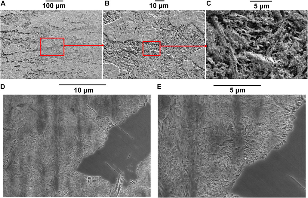
FIGURE 10. SEM micrographs of samples after heat treatment with the cooling rate 10°C/s [(A) after anodic polarization at 0.15 V vs. OCP with a crevice gap of 50 μm; (B) magnification of A; (C) magnification of B; (D) etched surface of the same sample as Figure 2D; (E) magnification of D].
By comparing the crevice-free and crevice corrosion behaviors, it is known that the two conditions did not agree with each other. Generally, microstructure refinement is able to improve corrosion resistance of pearlitic steel based on the literature (Ren, 2012; Ren et al., 2012; Al-Rubaiey et al., 2013; Katiyar et al., 2018). It is mostly ascribed to the microstructural homogenization [mainly regarding homogenous distribution of the micro-galvanic cell between the ferrite and cementite lamella (Katiyar et al., 2018)] ruling out less-ordered metallographic structure, which is often responsible for corrosion initiation. Corrosion normally initiates from local sites, and corrosion resistance can be improved due to statistically less initiation site. However, when it comes to crevice corrosion, an occlusive geometry increases corrosiveness of the crevice interior because steels are active in neutral NaCl and metal ions are inevitably dissolved and accumulated in crevice. Corrosion can take place auto-catalytically when the environment is corrosive enough, and refined microstructure alone is unable to effectively inhibit corrosion initiation. Homogenous microstructure tends to equalize corrosion initiating possibility of each local site on a certain region in which interfacial potential and chloride/proton distribution are almost homogenous. In this region, many tiny local sites (probably certain pearlitic nodules in the close range) have the equal possibility to be dissolved, which can quickly and easily coalesce before they can be observed as generalized dissolution of large area. In comparison, inhomogeneous microstructure results in preferential localized dissolution of bigger but more separated pearlitic nodules in a certain region even interfacial potential and chloride/proton distribution were homogenous in this region; so, the phenomenon of crevice corrosion initiating from some local spots can be more easily observed before it develops into dissolution of large area.
Since the rate of metal loss varied substantially between different samples, surface profiles need to be compared based on the same amount of metal loss instead of time. According to Figure 4B, the electric charge 0.2°C was a reasonable value (the surface would not be completely dissolved for all four samples), so the potentiostatic polarization at 0.15 V vs. OCP was carried out on each of the four samples and stopped when the electric charge reached 0.2°C. The surface profile mappings presenting dissolution depth and height information are shown in Figure 11.
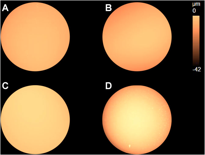
FIGURE 11. Surface profile mappings of the (A) as-received sample and samples after heat treatment with cooling rates (B) 2°C/s, (C) 5°C/s, and (D) 10°C/s after anodic polarization at 0.15 V vs. OCP stopped when the electric charge reached 0.2 C.
Distribution of the surface profile for the cooling rate 5°C/s appears to be uniform, indicating small dissolution depth. It agrees with the results shown in Figures 7, 9, where preferentially dissolved local spots and scratches due to grinding were still observed, respectively, in the dissolved area. As to the sample regarding the cooling rate 10°C/s, the edge region of the disc clearly shows darker color, indicating large dissolution depth near the edge. In addition, flocculent dissolution behavior can also be observed since some bright spots appear in the darker region near the edge.
To show the difference more clearly, Figure 12 presents surface profile data including sq (standard deviation of surface height, presenting the degree of surface height uniformity) and sz (maximum height difference between the peak and valley, representing the largest corrosion depth). The most uniform height distribution and smallest height difference between the peak and valley regarding the cooling rate 5°C/s should be resulted from small corrosion depth and generalized corrosion. In comparison, the least uniform height of the surface and biggest height difference between the peak and valley regarding the cooling rate 10°C/s should be resulted from the seriously corroded region near the edge, and the expansion of the dissolved area was slow (metal loss was mainly concentrated near the edge). This phenomenon was also observed in Figure 8, where the flocculently dissolved area was still near the edge until about 2 h (the whole surface was completely dissolved in 2 h as shown in Figure 7). The difference between the as-received sample and the sample after heat treatment with the cooling rate 2°C/s was negligible. It implies that the dissolved area based on the same amount of metal loss should be the biggest for 5°C/s and smallest for 10°C/s. Therefore, microstructure refinement tended to cause general corrosion of the whole crevice surface but further refinement led to corrosion concentrated near the crevice mouth (the edge).
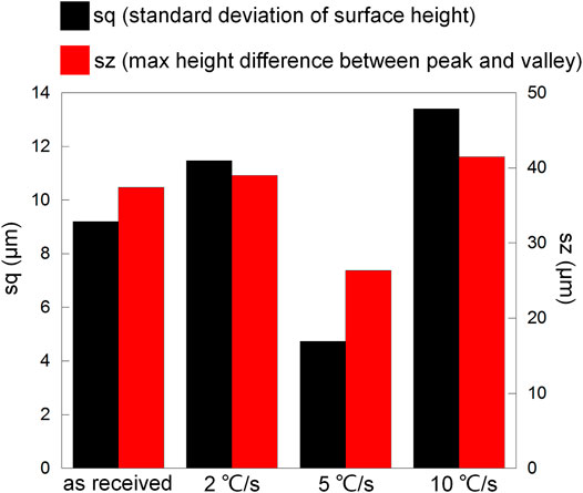
FIGURE 12. Surface profile data (sq and sz) regarding Figure 11.
Although microstructure refinement led to accelerated corrosion, it was mainly based on general corrosion with a small corrosion depth, which may cause uniform thinning of the rail foot. However, if microstructure is over refined, the corrosion rate was lowered but corrosion tended to be deep and non-uniform due to entangled cementite. The non-uniform dissolution area may act as a stress concentrator in the case of rail foot, suffering from strong downforce of the fastener. Therefore, although microstructure refinement is often applied for improvement of mechanical properties and corrosion resistance, one should be careful with the condition where crevice corrosion may occur.
The effect of pearlitic microstructure refinement (heat treatment with cooling rates 2, 5, and 10°C/s) on crevice corrosion has been studied on a typical high-speed rail steel U75V via facile in situ monitoring during electrochemical measurement. The main conclusions are as follows:
(1) The crevice corrosion rate increased after microstructure refinement, and the medium cooling rate 5°C/s resulted in the highest corrosion rate and expansion rate of the dissolved area.
(2) Dissolution of crevice interior developed from local spots for the as-received sample but tended to be generalized on the large area after microstructure refinement with cooling rates 2 and 5°C/s, ascribed to homogenization of pearlitic microstructure.
(3) Further refinement with the cooling rate 10°C/s resulted in entanglement of cementite, leading to preferential dissolution (appeared as flocculent expansion) on pearlitic nodules with entangled cementite. Dissolution largely concentrated on the preferentially dissolved region, lowering the expansion rate of the dissolved area.
(4) Based on the same amount of metal loss, uniformity of surface height was the highest and corrosion depth was the smallest for 5°C/s, while for 10°C/s it was vice versa..
The raw data supporting the conclusion of this article will be made available by the authors upon request, without undue reservation.
JW carried out most of the experimental work. BZ, WX, and JZ contributed to the conception and design of the study. WX wrote the draft of the manuscript and guided experimental work. LY and ZP helped on analysis of experimental data. BH helped on improvement of discussions in the manuscript. All authors contributed to manuscript revision and read and approved the submitted version.
This work was funded by the Shandong Provincial Natural Science Foundation, China (Grant No. ZR2019QEM011) and National Natural Science Foundation of China (Grant No. 41827805) and also supported by the Shandong Key Laboratory of Corrosion Science, China.
The authors declare that the research was conducted in the absence of any commercial or financial relationships that could be construed as a potential conflict of interest.
All claims expressed in this article are solely those of the authors and do not necessarily represent those of their affiliated organizations, or those of the publisher, the editors, and the reviewers. Any product that may be evaluated in this article, or claim that may be made by its manufacturer, is not guaranteed or endorsed by the publisher.
The authors appreciate the help of Mr. Yu Deng on SEM analysis.
Al-Rubaiey, S. I., Anoon, E. A., and Hanoon, M. M. (2013). The Influence of Microstructure on the Corrosion Rate of Carbon Steels. Eng. Technol. J. 31 (10), 1825–1836.
Clover, D., Kinsella, B., Pejcic, B., and De Marco, R. (2005). The Influence of Microstructure on the Corrosion Rate of Various Carbon Steels. J. Appl. Electrochem. 35 (2), 139–149. doi:10.1007/s10800-004-6207-7
Haisch, T., Mittemeijer, E. J., and Schultze, J. W. (2002). On the Influence of Microstructure and Carbide Content of Steels on the Electrochemical Dissolution Process in Aqueous NaCl-Electrolytes. Mater. Corrosion 53 (10), 740–755. doi:10.1002/1521-4176(200210)53:10<740:aid-maco740>3.0.co;2-j
Hernandez, F. C. R., Demas, N. G., Davis, D. D., Polycarpou, A. A., and Maal, L. (2007). Mechanical Properties and Wear Performance of Premium Rail Steels. Wear 263, 766–772. doi:10.1016/j.wear.2006.12.021
Hernandez, F. C. R., Plascencia, G., and Koch, K. (2009). Rail Base Corrosion Problem for North American Transit Systems. Eng. Fail. Anal. 16 (1), 281–294. doi:10.1016/j.engfailanal.2008.05.011
Hernandez-Valle, F., Edwards, R. S., Clough, A. R., Rosli, M. H., and Dutton, B. (2013). “Laser Generation and Detection for Surface Wave Interaction with Different Defect Geometries,” in Review of Progress in Quantitative Nondestructive Evaluation. Editors D.O. Thompson, and D.E. Chimenti (Melville: Amer Inst Physics), 32a and 32b, 324–329.
Hill, M. A., and Lillard, R. S. (2006). Methods for Accessing Pitting Damage in Carbon Steel Exposed to Alkaline Chloride Waste Environments. Corrosion 62 (9), 801–810. doi:10.5006/1.3278305
Hou, B., Li, X., Ma, X., Du, C., Zhang, D., Zheng, M., et al. (2017). The Cost of Corrosion in China. Npj Mater. Degrad. 1 (1), 4. doi:10.1038/s41529-017-0005-2
Katiyar, P. K., Misra, S., and Mondal, K. (2018). Effect of Different Cooling Rates on the Corrosion Behavior of High-Carbon Pearlitic Steel. J. Materi Eng. Perform. 27 (4), 1753–1762. doi:10.1007/s11665-018-3256-3
Li, Y., Guo, X., and Zhang, G. (2017). Synergistic Effect of Stress and Crevice on the Corrosion of N80 Carbon Steel in the CO 2 -Saturated NaCl Solution Containing Acetic Acid. Corrosion Sci. 123, 228–242. doi:10.1016/j.corsci.2017.05.005
Li, Y., Wang, X., and Zhang, G. (2020). Corrosion Behaviour of 13Cr Stainless Steel under Stress and Crevice in 3.5 wt.% NaCl Solution. Corrosion Sci. 163, 108290. doi:10.1016/j.corsci.2019.108290
Liu, J. P., Zhou, Q. Y., Zhang, Y. H., Liu, F. S., Tian, C. H., Li, C., et al. (2019). The Formation of Martensite during the Propagation of Fatigue Cracks in Pearlitic Rail Steel. Mater. Sci. Eng. A 747, 199–205. doi:10.1016/j.msea.2019.01.049
Murase, Y., Masuda, H., and Katayama, H. (2021). Corrosion Resistance of Finer/Coarser Pearlitic Structures of Carbon Steel. J. Electrochem. Soc. 168 (4), 041501. doi:10.1149/1945-7111/abf185
Neetu, V., Katiyar, P. K., Sangal, S., and Mondal, K. (2021). Effect of Various Phase Fraction of Bainite, Intercritical Ferrite, Retained Austenite and Pearlite on the Corrosion Behavior of Multiphase Steels. Corrosion Sci. 178, 109043. doi:10.1016/j.corsci.2020.109043
Panda, B., Balasubramaniam, R., and Dwivedi, G. (2008). On the Corrosion Behaviour of Novel High Carbon Rail Steels in Simulated Cyclic Wet-Dry Salt Fog Conditions. Corrosion Sci. 50 (6), 1684–1692. doi:10.1016/j.corsci.2008.02.021
Panda, B., Balasubramaniam, R., Mahapatra, S., and Dwivedi, G. (2009). Fretting and Fretting Corrosion Behavior of Novel Micro Alloyed Rail Steels. Wear 267 (9-10), 1702–1708. doi:10.1016/j.wear.2009.06.035
Ren, A. C., Zhou, H., Zhu, M., and Yuan, Z. X. (2012). Comparative Study on the Cyclic Corrosion Test of Rail Steel U68CuCr and U75V. Adv. Mater. Res. 616-618, 1059–1062. doi:10.4028/www.scientific.net/AMR.616-618.1059
Ren, A. (2012). PhD Thesis: Research on High-Strength and Corrosion Resistance Rail. PhD thesis. Wuhan: Wuhan University of Science and Technology.
Safa, M., Sabet, A., Ghahremani, K., Haas, C., and Walbridge, S. (2015). Rail Corrosion Forensics Using 3D Imaging and Finite Element Analysis. Int. J. Rail Transportation 3 (3), 164–178. doi:10.1080/23248378.2015.1054622
Shariff, S. M., Pal, T. K., Padmanabham, G., and Joshi, S. V. (2013). Influence of Chemical Composition and Prior Microstructure on Diode Laser Hardening of Railroad Steels. Surf. Coat. Technol. 228, 14–26. doi:10.1016/j.surfcoat.2013.03.046
Shurpali, A. A., Van Dam, E., Edwards, J. R., Lange, D. A., and Barkan, C. P. L. (2012). Laboratory Investigation of the Abrasive Wear Mechanism of concrete Crosstie Rail Seat Deterioration (Rsd). New York: Amer Soc Mechanical Engineers.
Toribio, J., and Ovejero, E. (2001). Microstructure-Based Modelling of Localized Anodic Dissolution in Pearlitic Steels. Mater. Sci. Eng. A 319-321, 308–311. doi:10.1016/s0921-5093(01)01009-7
Wu, S., Liu, L., and Peng, J. (2020). Influence of Pearlite Interlamellar Spacing on Initial Corrosion of U71Mn Heavy Rail Steel. Trans. Mater. Heat Treat. 41 (11), 87–93. doi:10.13289/j.issn.1009-6264.2020-0209
Xu, W., Street, S. R., Amri, M., Mosselmans, J. F. W., Quinn, P. D., Rayment, T., et al. (2015). In-Situ Synchrotron Studies of the Effect of Nitrate on Iron Artificial Pits in Chloride Solutions. (Ii). On the Effect of Carbon. J. Electrochem. Soc. 162 (6), C243–C250. doi:10.1149/2.0591506jes
Xu, W., Rayment, T., and Davenport, A. (2017). The Effect of Carbon within Corrosion Pits of Iron in Chloride Solutions. Corrosion Eng. Sci. Technol. 52 (5), 383–390. doi:10.1080/1478422x.2017.1304618
Xu, W., Zhang, B., Yang, L., Li, T., and Li, Y. (2019). Liquid-Air Interface Corrosion of A537 Steel in High Level Liquid Radioactive Waste Simulant in a Sealed Container. J. Electrochem. Soc. 166 (2), C33–C41. doi:10.1149/2.0421902jes
Xu, W., Zhang, B., Deng, Y., Wang, Z., Jiang, Q., Yang, L., et al. (2021). Corrosion of Rail Tracks and Their protection. Corrosion Rev. 39 (1), 1–13. doi:10.1515/corrrev-2020-0069
Xu, W., Deng, Y., Zhang, B., Zhang, J., Peng, Z., Hou, B., et al. (Forthcoming 2022). Crevice Corrosion of U75V High-speed Rail Steel with Varying Crevice Gap Size by In-Situ Monitoring. J. Mater. Res. Technol. doi:10.1016/j.jmrt.2021.12.116
Yazici, O., and Yilmaz, S. (2018). Investigation of Effect of Various Processing Temperatures on Abrasive Wear Behaviour of High Power Diode Laser Treated R260 Grade Rail Steels. Tribology Int. 119, 222–229. doi:10.1016/j.triboint.2017.11.006
Keywords: microstructure, crevice corrosion, pearlite, cooling rate, U75V rail steel, interlamellar spacing
Citation: Wang J, Zhang B, Xu W, Zhang J, Yang L, Peng Z and Hou B (2022) Microstructure Refinement on Crevice Corrosion of High-Speed Rail Steel U75V Visualized by an In Situ Monitoring System. Front. Mater. 8:820721. doi: 10.3389/fmats.2021.820721
Received: 23 November 2021; Accepted: 13 December 2021;
Published: 07 January 2022.
Edited by:
Changdong Gu, Zhejiang University, ChinaReviewed by:
Jichao Li, the Ohio State University, United StatesCopyright © 2022 Wang, Zhang, Xu, Zhang, Yang, Peng and Hou. This is an open-access article distributed under the terms of the Creative Commons Attribution License (CC BY). The use, distribution or reproduction in other forums is permitted, provided the original author(s) and the copyright owner(s) are credited and that the original publication in this journal is cited, in accordance with accepted academic practice. No use, distribution or reproduction is permitted which does not comply with these terms.
*Correspondence: Weichen Xu, dy54dUBxZGlvLmFjLmNu; Jie Zhang, emhhbmdqaWVAcWRpby5hYy5jbg==
Disclaimer: All claims expressed in this article are solely those of the authors and do not necessarily represent those of their affiliated organizations, or those of the publisher, the editors and the reviewers. Any product that may be evaluated in this article or claim that may be made by its manufacturer is not guaranteed or endorsed by the publisher.
Research integrity at Frontiers
Learn more about the work of our research integrity team to safeguard the quality of each article we publish.