 Sen Hu1
 Tao Fu
 Xianghe Peng
- 1Department of Engineering Mechanics, Chongqing University, Chongqing, China
- 2State Key Laboratory of Coal Mine Disaster Dynamics and Control, Chongqing University, Chongqing, China
- 3Advanced Manufacturing Engineering, Chongqing University of Posts and Telecommunications, Chongqing, China
- 4Department of Aerospace Engineering, Tohoku University, Sendai, Japan
Stacking fault tetrahedron (SFT) is a kind of detrimental three-dimensional defect in conventional face-centered cubic (FCC) structural metals; however, its formation and anisotropic mechanical behavior in a CoCrFeNiMn high-entropy alloy (HEA) remain unclear. In this work, we first performed molecular dynamics simulations to verify the applicability of the Silcox-Hirsch mechanism in the CoCrFeNiMn HEA. The mechanical responses of the SFT to shear stress in different directions and that of the pure Ni counterpart were simulated, and the evolutions of the atomic structures of the SFTs during shear were analyzed in detail. Our results revealed that the evolution of the SFT has different patterns, including the annihilation of stacking faults, the formation and expansion of new stacking faults, and insignificant changes in stacking faults. It was found that the effects of SFT on the elastic properties of Ni and HEA are negligible. However, the introduction of SFT would reduce the critical stress, while the critical stress of the CoCrFeNiMn HEA is much less sensitive to SFT than that of Ni.
1 Introduction
The defects, including stacking fault tetrahedrons (SFTs), voids, dislocation loops, and bubbles, would be generated in metals subjected to long-term irradiation or severe deformation (Wu et al., 2018b; Wu et al., 2018c; Zhang et al., 2018; Chen et al., 2020). These defects would affect the mechanical properties of materials, such as irradiation hardening, swelling, embrittlement, and irradiation-assisted stress corrosion cracking (Bacon et al., 2009). The morphology and distribution of defects caused by irradiation depend on the lattice structure of materials and irradiation conditions. In face-centered cubic (FCC) metals, SFT is a kind of detrimental three-dimensional immobile defect (Singh et al., 2004; Wang et al., 2011a; Wang et al., 2011b; Wang et al., 2011c), which is predominantly generated from vacancy clusters (Kojima et al., 1991). In irradiated Cu, most SFTs are very small with the size of 2–3 nm but with a high density of about 1,022–1,024/m3 (Kapinos et al., 1989; Fabritsiev and Pokrovsky, 2007).
SFT significantly affects the mechanical properties of materials (Matsukawa et al., 2005; Zhang et al., 2017a; Zhang et al., 2017b; Zhang et al., 2018). SFT can interact with dislocations and absorb them, forming defect-free channels, in which dislocations can glide freely, resulting in the localization of plastic flow and loss of ductility (Robach et al., 2003; McMurtrey et al., 2014). Dai and Victoria (2011) proposed that the forming ability of SFT is closely related to the stacking fault energy (SFE): the lower the SFE, the easier the SFT is to form. High-entropy alloys (HEAs), as a new type of high-performance alloy, have attracted considerable attention due to their excellent mechanical properties and designability (Li et al., 2018; Feng et al., 2020; Luo et al., 2021; Peng et al., 2021; Ren et al., 2021). The SFEs of FCC HEAs are usually low (Huang et al., 2015; Chandan et al., 2021), and are even of negative values (Zhao et al., 2017), indicating that SFTs would form more easily in HEAs than in conventional alloys. CoCrFeNiMn is a kind of the most concerned FCC HEAs due to its excellent mechanical properties (Okamoto et al., 2016).
Based on the Silcox-Hirsch mechanism, SFTs can form after the aggregation of vacancies (Silcox and Hirsch, 1959a), generated under long-term irradiation or severe deformation in conventional metals. Despite the rapid development of experimental technology, it is still very challenging to study the evolution of SFTs under shear stress in different directions through experiments. Molecular dynamics (MD) simulations is an effective means to investigate the formation and evolution of microstructures under irradiation (Aidhy et al., 2015; Drouet et al., 2016; Dai et al., 2017; Zhu et al., 2017; Leino et al., 2018; Ke et al., 2019) and various mechanical loading (Weng et al., 2020; Chen et al., 2021; Weng et al., 2021), and the evolution of SFTs (Wu et al., 2018b; Wu et al., 2018c; Zhang et al., 2018; Chen et al., 2020). To study the formation and aggregation of vacancies using MD simulation of irradiation requires a long time and a lot of computing resources. Therefore, to study the effect of SFTs on the mechanical properties using MD simulations, SFTs are usually generated by minimizing and relaxing the system containing a planar triangular vacancy zone (Wu et al., 2017; Wu et al., 2018a; Wu et al., 2018b; Wu et al., 2018c). Based on the above considerations, we mainly focus on the process after the aggregation of vacancies to explore whether the Silcox-Hirsch formation mechanism of SFT applies to HEAs due to the severe lattice distortion caused by the multi-principal elements. If applicable, the effect of SFTs in HEAs on mechanical properties needs to be studied.
In this work, we use MD simulations to explore the following two questions: 1) the feasibility of the Silcox-Hirsch formation mechanism in HEAs, 2) the effect of SFT on the mechanical property of HEAs and the evolutions of SFTs under shear along different directions.
2 Simulation Details
Figure 1 is the schematic illustration of the simulation process in this work. We first build pure Ni and CoCrFeNiMn HEA samples containing approximately 290,000 atoms, where the x, y, and z axes are parallel with
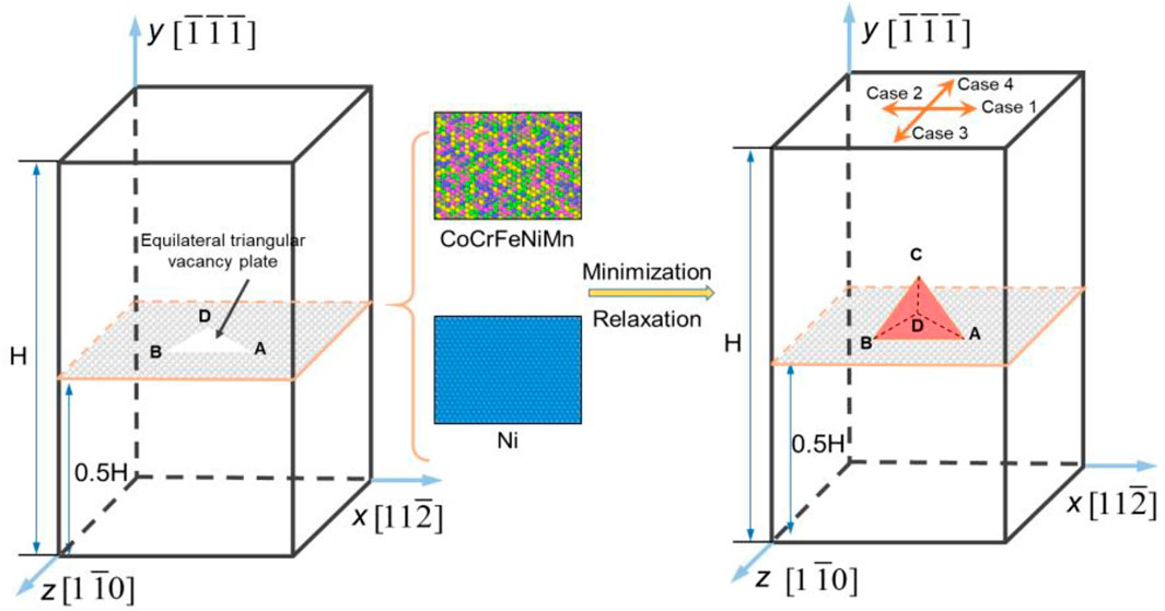
FIGURE 1. Schematic illustration of the simulation process. Case 1 to Case 4 indicate that the shear directions are
The second nearest-neighbor modified embedded-atom method (2NN MEAM) potential and the parameters developed by Choi et al. (2018) are employed to describe the interaction between the atoms, which have been widely used in the MD simulation of mechanical behaviors of CoCrFeNiMn HEA (Fang et al., 2019; Lee et al., 2021; Wang et al., 2021; Zhou et al., 2021). The stacking fault energy of CoCrFeNiMn calculated using these potential parameters is negative, consistent with first-principles calculation results (Zhao et al., 2017), which further demonstrates the validity of the potential. All simulations are carried out using the Large-scale Atomic/Molecular Massively Parallel Simulator (LAMMPS) (Plimpton, 1995).
Microstructures and deformation behaviors are analyzed with the adaptive common neighbor analysis (CNA) (Tsuzuki et al., 2007), dislocation extraction analysis (DXA) (Stukowski and Albe, 2010), and visualized using OVITO (Stukowski, 2010). The Burgers vector of dislocation, slip direction and slip plane are described using the Thompson tetrahedral notation (Silcox and Hirsch, 1959b; Wu et al., 2017).
3 Results and Analyses
3.1 Applicability of Silcox-Hirsch Mechanism in HEAs
Figure 2 shows the formation of a perfect SFT in CoCrFeNiMn from an equilateral planar triangle vacancy zone, which can be divided into four steps:
1) At t = 2.3 ps, the distances between the atoms on the upper and lower the planar triangular vacancy zone becomes smaller, forming a triangular Frank dislocation loop, whose three edges are dislocations γC, as shown in Figure 2A. The stacking sequence of the triangular area along the y-axis is ABCBC; therefore, this triangular area is an intrinsic stacking fault (SF).
2) The Frank dislocation loop γC is dissociated on different planes as follows,
On the α plane: γC(α)→ γα + αC
On the β plane: γC(β)→ γβ + βC
On the δ plane: γC(δ)→ γδ + δC.
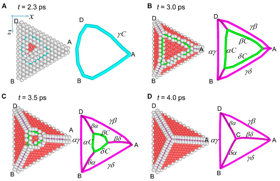
FIGURE 2. Formation of SFT in CoCrFeNiMn. (A) Frank dislocation loop γC, (B) dissociation of Frank dislocations, (C) glide of Shockley partial dislocation, (D) perfect SFT, with red atoms representing SF.
Therefore, three stair-rod dislocations (SRDs), γα, γβ and γδ, and three Shockley partial dislocations (SPDs), αC, βC and δC, are obtained, as shown in Figure 2B.
3) The SRDs and SPDs on the same slip plane repel each other due to the acute intersection angle between their Burgers vector, causing the glide of SPDs on their respective slip planes. The glide of SPDs brings in the formation of SF on theirs slip planes (α, β, and δ), as shown in Figures 2B,C.
4) At the same time, the SPDs on the three slip planes intersect in pairs, forming three SRDs (αβ, δβ, and αδ) as follows:
The intersection of α and β planes: αC + Cβ → αβ
The intersection of δ and β planes: δC + Cβ → δβ
The intersection of α and δ planes: αC + Cδ → αδ
Three SRDs αβ, δβ, and αδ are synthesized (Figures 2B,C), and finally, intersect at Point C (Figure 2D). At this point, a formation of a perfect SFT is finished, containing four SFs and six SRDs. The above process agrees with the Silcox-Hirsch formation mechanism of SFT in traditional metals, indicating that this mechanism is also applicable in FCC HEAs.
3.2 Transformation of SFT
3.2.1 Case 1
Figures 3A–F show the atomic structure of the SFT in Ni sample sheared along
1) Annihilation of the SF on the γ plane. With the increase of ε, two SRDs (γδ and γβ) near Point A are dissociated into three SPDs (γA, Aδ, and Aβ) at ε = 0.0638, by
2) Annihilation of the SF on the α plane. At ε = 0.0886, two SRDs (δα and βα) near Point C are dissociated into three SPDs (Cα, δC and βC). Before the reaction of the dislocations on the α plane, the basal plane (γ) of the SFT has annihilated. Then, SPD Cα glides on α plane, and the SF on α plane annihilates gradually, as shown in Figure 3D, which is similar to the annihilation of the SF on γ plane. At ε = 0.0902, SPD Cα reacts with FPD αA, forming a perfect dislocation CA with Burgers vector of
3) Expansion of SFs on the δ and β planes. After the above two stages, the SFs on γ and α planes annihilate entirely, leaving two enlarged SFs on the δ and β planes. With the increase of strain, the ends of the perfect dislocation CA are pinned, but the SPDs on δ and β planes continue to glide on their slip planes, contributing to the expansion of the SFs on the δ and β planes. Eventually, it evolves into a structure where two SFs intersect at 60°, as shown in Figure 3F.
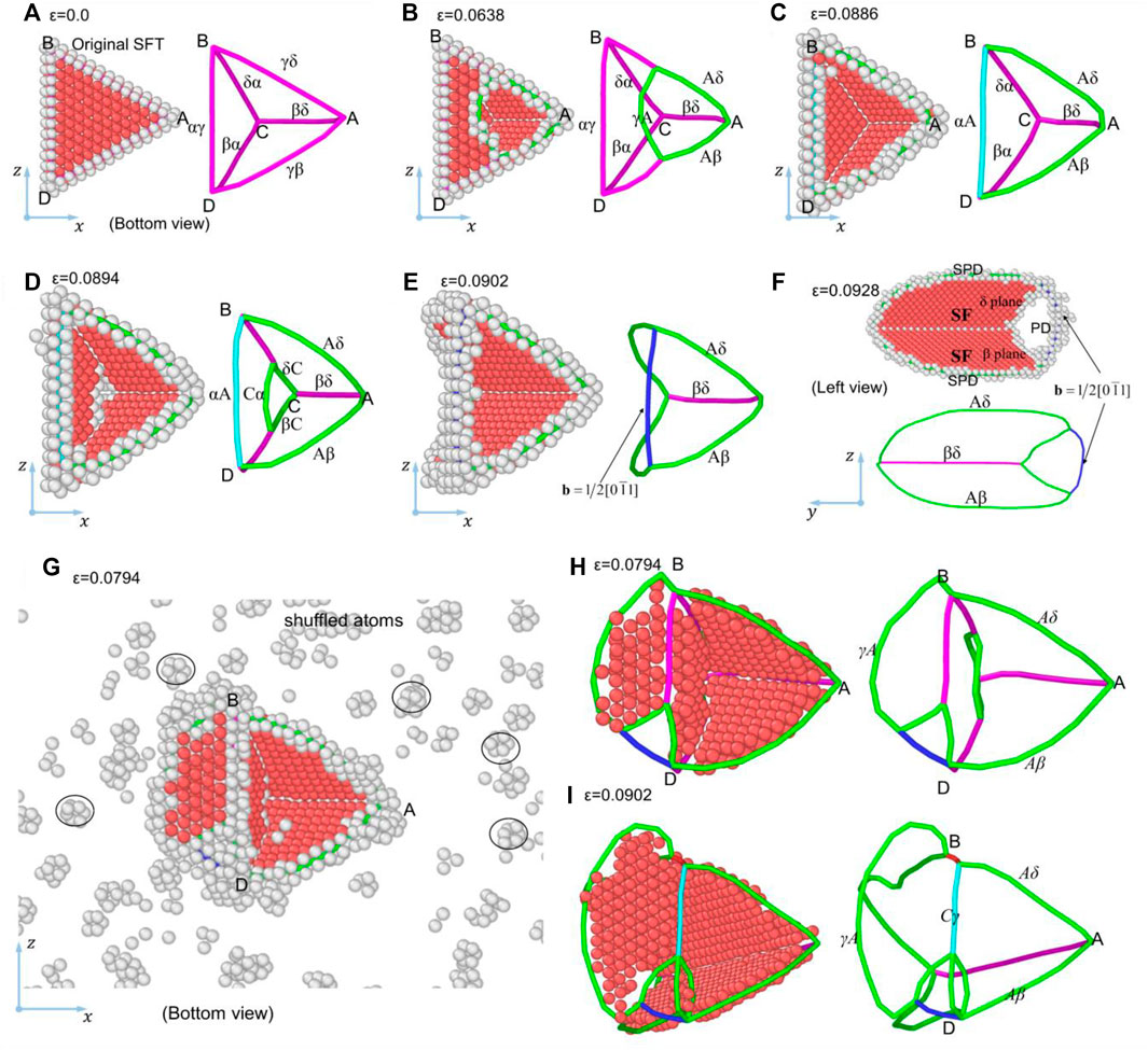
FIGURE 3. Atomic structure of SFTs in Ni and CoCrFeNiMn samples sheared along
Figures 3G–I show the atomic structure of the SFT in the CoCrFeNiMn sample under shear along
At ε = 0.0902, the SRDs δα and βα near Point C are dissociated into three SPDs, Cα, δC and βC, among which, Cα glides on the α plane, and the SF on the α plane annihilates gradually. Afterward, Cα meets with the SRD αγ, generating an FPD Cγ (
In this case, there are some differences between the response of CoCrFeNiMn and that of Ni. First, the reaction of γA on the basal plane with the SRD αγ of SFT does not generate Frank partial dislocation, but continues to slip forward, forming SFs on the left side of BD. Second, no dissociation of SRDs on the γ and α planes occurs. Third, there are more shuffled atoms in CoCrFeNiMn than in Ni.
3.2.2 Case 2
The evolution of microstructures in the Ni sample sheared along
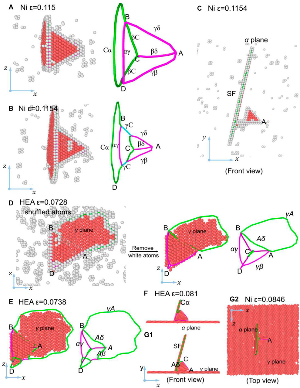
FIGURE 4. Atomic structure of SFT in Ni and CoCrFeNiMn samples sheared along
After these reactions between dislocations and the further glide of dislocations, the SF on the α plane expands. Then a part of SPDs δC and βC react with SPDs γδ and γβ at Points B and D, forming two Frank dislocations γC, as shown in Figure 4B. The reactions can be expressed as,
The above dislocation reaction shortens the dislocations δC and βC, leading to a reduction in the height of the SFT (from 15 atomic layers to 10 atomic layers). In general, the most critical microstructure evolution under shear along
Figures 4D–G show the atomic structures of the SFT in CoCrFeNiMn under shear along
3.2.3 Case 3
Figures 5A–D show the atomic structures of the SFT in the Ni sample sheared along
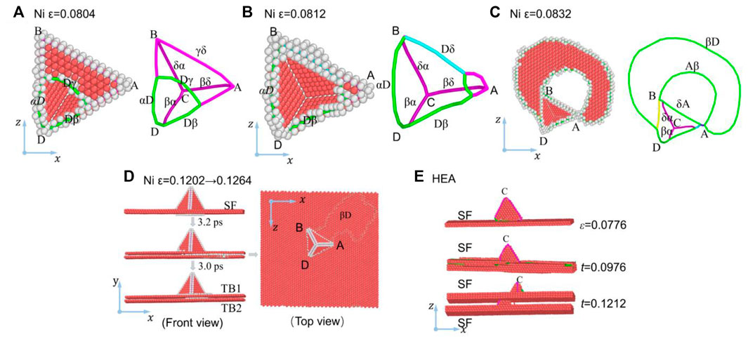
FIGURE 5. Atomic structures of SFTs in Ni and CoCrFeNiMn samples sheared along
With the increase of shear strain, the γD reacts with the δγ, forming an FPD δD (
The formation of TBs can be illustrated in Figure 6. A dislocation nucleates from the SFT and glides, forming a stacking fault, with the stacking sequence varying from ABCABCA … to ABCBCAB … Then, an SPD glides on the plane that is one atomic layer higher than the γ plane, resulting in an upward movement of the upper atomic layer of the SF and separating the two atomic layers in the SF structure. The stacking sequence varies from ABCBCAB … to ABCBABC … Subsequently, new SPD nucleates from the SFT and glides on a higher atomic plane, contributing to the upward movement of the upper atomic layer of the SF. Accordingly, the stacking sequence varies from ABCBABC … to ABCBACA … With the glide of the dislocation, the upper atomic layer of the SF moves upwards, increasing the spacing between the two atomic layers and the formation of two TBs. This evolution causes the upward movement of the bottom plane of the SFT, which reduces the SFT height.
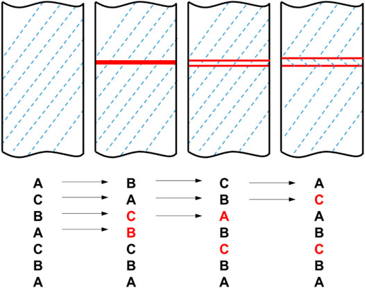
FIGURE 6. Illustration for the formation of TBs.
Figure 5E shows the microstructures in CoCrFeNiMn under shear along
3.2.4 Case 4
For Ni, the microstructural evolution in Case 4 is similar to that in Case 3, except that the SF forms on the β plane. At ε = 0.0826, the SRD near Point D is dissociated into three SPDs, αD, γD, and Dβ. Then, γD glides on the γ plane, yielding a SF at ε = 0.099, as shown in Figure 7A. Different from Case 3, the SRDs, βδ and βα, near the vertex C, are dissociated into three SPDs, βC, Cδ and Cα. The SPD βC glides on its slip plane, generating a new SF on the β plane, as shown in Figure 7B. The dissociation of βδ and βα can be expressed as
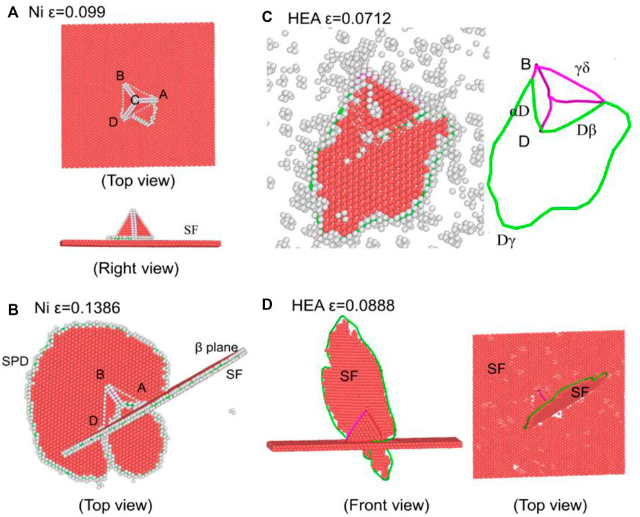
FIGURE 7. Atomic structures of SFTs in Ni and CoCrFeNiMn samples sheared along
Figures 7C,D show the atomic structures of the SFT in CoCrFeNiMn under shear along
4 Discussion
The shear stress-strain (σ−ε) curves of Ni and the CoCrFeNiMn HEA samples (each containing a SFT at its center) subjected to shear deformation in the four directions at 300 K are shown in Figure 8A. For comparison, the same shear simulations of Ni and the CoCrFeNiMn HEA samples without any SFT are performed, and the σ−ε curves are shown in Figure 8B. The σ−ε curves of Ni are higher than those of CoCrFeNiMn, which should be ascribed to the higher generalized stacking fault (GSF) energy curves of Ni (Figure 8C). For Ni and the HEA, the shear direction in Case 1 and Case 3 is opposite to that in Case 2 and Case 4, respectively. Therefore, for the Ni and HEA samples with or without a SFT, the σ−ε curves in Case 1 are higher than those in Case 2, while those in Case 3 and Case 4 almost coincide, which could be attributed to the symmetry of atomic arrangement. From the GSF energy curves in Figure 8C, one can see that the curves of (111)<110> are bilaterally symmetric, i.e., the curves from the relative displacement from 0.0 to 1.0 (Case 3) are equivalent to those from the relative displacement from 1.0 to 0.0 (Case 4); while the curves of (111)<112> are asymmetrical, indicating that gliding in Case 2 is much easier than that in Case 1. Therefore, Case 2 and Case 1 are usually referred to as “Easy” and “Hard” slip direction, respectively (Li et al., 2014; Li et al., 2016; Yang et al., 2019). The shear modulus G can be obtained by fitting the slope of these curves at the initial stage, as listed in Table 1, where it can be seen that the shear moduli of the samples with SFT are consistent with that of samples without SFT for both Ni and HEA, indicating that SFT has a negligible effect on the G.
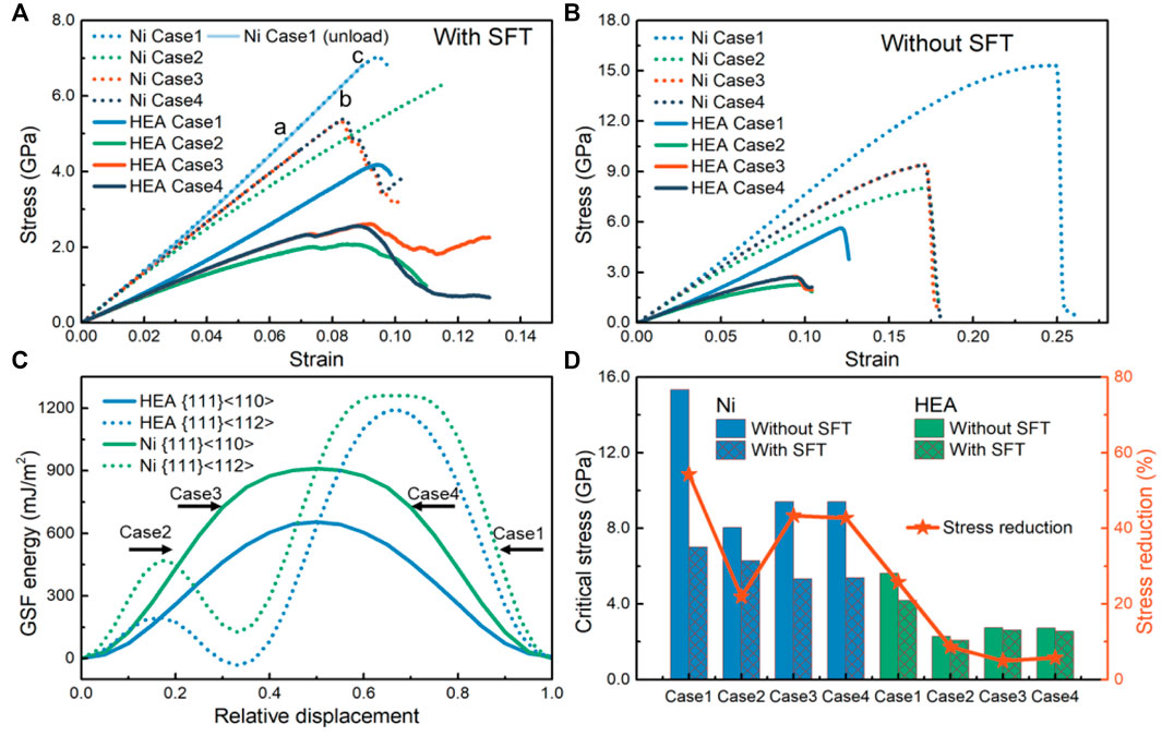
FIGURE 8. Shear stress-strain curves of Ni and CoCrFeNiMn HEA samples sheared along four directions at 300 K. (A) with SFT; (B) without SFT; (C) Variations of GSF energies of different slip systems with relative displacement; (D) Comparison of critical shear stress between samples with and without SFT.
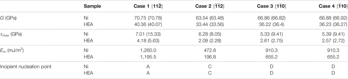
TABLE 1. Shear moduli (G), critical shear stresses (τmax), energy barriers (Em) and incipient nucleation points of Ni and CoCrFeNiMn HEA samples with a SFT under shear along different directions. The results of samples without SFT are provided in brackets ( ) for comparison.
The energy barrier Em is usually used to predict the slip order; the higher the energy barrier, the more difficult the glide (Yadav et al., 2014; Fu et al., 2015a; Fu et al., 2015b). For the Ni and CoCrFeNiMn samples without SFT, the relationship of critical shear stress τ of the four cases is
Since the maximum stress here does not correspond to dislocation nucleation and the annihilation of the γ plane does not lead to a drop in stress, the sudden drop in stress should correspond to plastic deformation. For example, in Case 1 for Ni, the microstructures at Points “a” and “b” in Figure 8A correspond to the dissociation of SRDs and the annihilation of the SF on the α plane (Figures 3B,D), but the shear stress remains increasing, and the crystal is in the initial stage of plastic deformation. Then, the glide of SPD induces the SFs on the δ and β planes, resulting in a drop in stress. To further explore the response of the annihilation of SF on the γ plane to the stress, we perform an unloading simulation from ε = 0.092 (Point “c” in Figure 8A), and found that the SFT returns to its original shape. It can be speculated that the energy stored in the material could provide the energy required for the recovery. In Case 2 for Ni, the formation of the SFs on the α plane causes the drop in stress, while in Case 3 and Case 4, the annihilation of the SF on the γ plane induces the drop in stress.
Figure 8D shows the comparison of critical shear stress between the samples containing SFT with those without containing SFT, where one can see that the introduction of SFT would reduce the mechanical properties of both Ni and the HEA. However, the stress reduction caused by SFT in the HEA for each case is much less than that in Ni, showing that the mechanical properties of the HEA are less dependent on SFT. This weaker dependence may be attributed to the self-adjustment of the internal stress due to the multi-component nature of HEA.
During shear, besides the slip and evolution of dislocations, there are some atoms that are far from their equilibrium positions and are identified as shuffled atoms. These shuffled atoms can only be observed in the Ni sample in Case 2, but can be observed commonly in the CoCrFeNiMn samples subjected to shear along different directions, which could be ascribed to the lattice distortion effect.
The dislocation nucleation points in the Ni and CoCrFeNiMn HEA samples subjected to shear deformation along different directions are summarized and shown in Table 1. The positions of incipient nucleation of dislocations are all from the three vertices of the SFTs (A, C and D in Figure 1). Dislocation nucleates from Point A in Case 1; from Point C in Case 2; and from Point D in Case 3 and Case 4, indicating that the site of incipient nucleation of dislocations is related to the shear direction.
The microstructures in Ni and the CoCrFeNiMn HEA are versatile in different cases, but the primary evolutions are all around the four planes of the SFT (α, β, δ, γ), including the annihilation of SF (Annihilation) and formation and expansion of new SFs (Expansion) and insignificant changes of SFs (Invariance), as summarized in Table 2. On the α, β and δ planes, no significant differences can be detected between Ni and CoCrFeNiMn for each case; but on the γ plane, there are distinct differences between Ni and CoCrFeNiMn for both Case 1 and Case 2. In the CoCrFeNiMn sample, a new SF forms; while in Ni, the SF annihilates and keeps invariant in Case 1 and Case 2, respectively. Another essential difference of the microstructures in Ni with that in the CoCrFeNiMn HEA is that the dislocation lines in Ni are smooth, while that in the HEA are more tortuous, which can also be attributed to the multi-component feature.
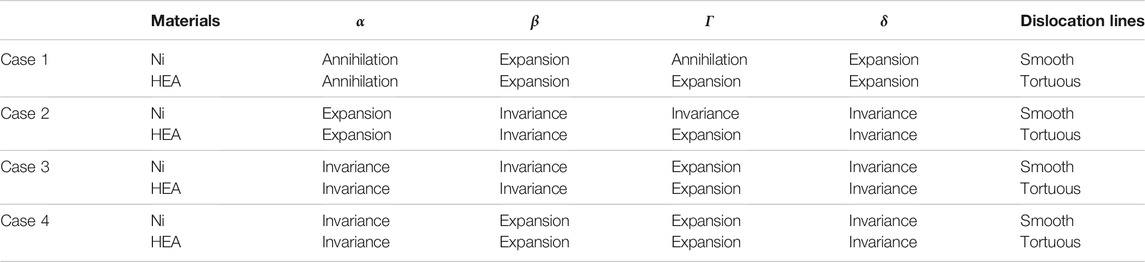
TABLE 2. Final states of SFTs and characteristics of dislocation lines in Ni and CoCrFeNiMn HEA samples sheared in different directions. Annihilation denoting annihilation of SF; Expansion, formation and expansion of new SF; invariance, insignificant changes in stacking faults.
5 Conclusion
In this work, the energy minimization and relaxation for the Ni and CoCrFeNiMn high-entropy alloy (HEA) samples containing an equilateral planar triangular vacancy zone were simulated with molecular dynamics (MD), aiming to verify the applicability of the Silcox-Hirsch mechanism in the formation of stacking fault tetrahedrons (SFTs) in CoCrFeNiMn HEAs. Then, the mechanical responses of the SFTs in the Ni and HEA samples subjected to shear deformation along different directions, as well as the evolutions of their atomic structures, were studied comparatively in detail. It was shown that the evolutions of the SFTs have various patterns, including the annihilation of stacking faults, formation and expansion of new stacking faults, and insignificant changes in stacking faults. The effects of SFT on the elastic properties of Ni and HEA are negligible. However, the introduction of SFT would reduce the critical stress in both Ni and the HEA, but the reduction in the HEA is much smaller than that in Ni. It was also found that the site of incipient nucleation of dislocations is related to the shear direction.
It should be noted that the chemical short-range order may be of great significance to the formation and evolution of stacking fault tetrahedrons, which requires hybrid MD and Monte Carlo simulations to obtain HEAs with optimized chemical short-range order.
Data Availability Statement
The original contributions presented in the study are included in the article/Supplementary Material, further inquiries can be directed to the corresponding authors.
Author Contributions
SH, SW, and TF designed the scheme and wrote the manuscript under the guidance of XP. SH, QL, and TF performed the calculations and analyzed the results. YZ and XC participated in the discussions and provided valuable suggestions. All authors contributed to the manuscript, read and approved the submitted version.
Funding
This work is supported by the National Natural Science Foundation of China (Nos 11932004, 11802045, and 11802047) and the Chongqing Natural Science Foundation (No. cstc2019jcyj-bshX0029). This work was performed at Lv Liang Cloud Computing Center of China, and the calculations were performed on TianHe-2.
Conflict of Interest
The authors declare that the research was conducted in the absence of any commercial or financial relationships that could be construed as a potential conflict of interest.
Publisher’s Note
All claims expressed in this article are solely those of the authors and do not necessarily represent those of their affiliated organizations, or those of the publisher, the editors and the reviewers. Any product that may be evaluated in this article, or claim that may be made by its manufacturer, is not guaranteed or endorsed by the publisher.
References
Aidhy, D. S., Lu, C., Jin, K., Bei, H., Zhang, Y., Wang, L., et al. (2015). Point Defect Evolution in Ni, NiFe and NiCr Alloys from Atomistic Simulations and Irradiation Experiments. Acta Mater. 99, 69–76. doi:10.1016/j.actamat.2015.08.007
Bacon, D. J., Osetsky, Y. N., and Rodney, D. (2009). “Chapter 88 Dislocation-Obstacle Interactions at the Atomic Level,” in Dislocations in Solids. Editor J. P. H. Kubin (Amsterdam, Netherlands: Elsevier), 1–90. doi:10.1016/s1572-4859(09)01501-0
Chandan, A. K., Tripathy, S., Sen, B., Ghosh, M., and Ghosh Chowdhury, S. (2021). Temperature Dependent Deformation Behavior and Stacking Fault Energy of Fe40Mn40Co10Cr10 alloy. Scr. Mater. 199, 113891. doi:10.1016/j.scriptamat.2021.113891
Chen, X., He, X., Chen, Y., Jia, L., Yang, W., Hu, W., et al. (2020). Molecular Dynamics Simulation of the Interactions between Screw Dislocation and Stacking Fault Tetrahedron in Fe-10Ni-20Cr and Ni. Model. Simul. Mater. Sci. Eng. 28, 075002. doi:10.1088/1361-651x/abac50
Chen, X., Weng, S., Yue, X., Fu, T., and Peng, X. (2021). Effects of Anisotropy and In-Plane Grain Boundary in Cu/Pd Multilayered Films with Cube-On-Cube and Twinned Interface. Nanoscale Res. Lett. 16, 69. doi:10.1186/s11671-021-03528-9
Choi, W.-M., Jo, Y. H., Sohn, S. S., Lee, S., and Lee, B.-J. (2018). Understanding the Physical Metallurgy of the CoCrFeMnNi High-Entropy alloy: an Atomistic Simulation Study. Npj Comput. Mater. 4, 1. doi:10.1038/s41524-017-0060-9
Dai, Y., and Victoria, M. (2011). Defect Cluster Structure and Tensile Properties of Copper Single Crystals Irradiated with 600 MeV Protons. MRS Proc. 439, 319. doi:10.1557/proc-439-319
Dai, C., Saidi, P., Yao, Z., and Daymond, M. R. (2017). Atomistic Simulations of Ni Segregation to Irradiation Induced Dislocation Loops in Zr-Ni Alloys. Acta Mater. 140, 56–66. doi:10.1016/j.actamat.2017.08.016
Drouet, J., Dupuy, L., Onimus, F., and Mompiou, F. (2016). A Direct Comparison between In-Situ Transmission Electron Microscopy Observations and Dislocation Dynamics Simulations of Interaction between Dislocation and Irradiation Induced Loop in a Zirconium alloy. Scr. Mater. 119, 71–75. doi:10.1016/j.scriptamat.2016.03.029
Fabritsiev, S. A., and Pokrovsky, A. S. (2007). Effect of Irradiation Temperature on Microstructure, Radiation Hardening and Embrittlement of Pure Copper and Copper-Based alloy. J. Nucl. Mater. 367-370, 977–983. doi:10.1016/j.jnucmat.2007.03.056
Fang, Q., Chen, Y., Li, J., Jiang, C., Liu, B., Liu, Y., et al. (2019). Probing the Phase Transformation and Dislocation Evolution in Dual-phase High-Entropy Alloys. Int. J. Plast. 114, 161–173. doi:10.1016/j.ijplas.2018.10.014
Feng, H., Cui, S., Chen, H., Song, X., Fang, Q., Li, J., et al. (2020). A Molecular Dynamics Investigation into Deformation Mechanism of Nanotwinned Cu/high Entropy alloy FeCoCrNi Nanolaminates. Surf. Coat. Techn. 401, 126325. doi:10.1016/j.surfcoat.2020.126325
Fu, T., Peng, X., Huang, C., Yin, D., Li, Q., and Wang, Z. (2015a). Molecular Dynamics Simulation of VN Thin Films under Indentation. Appl. Surf. Sci. 357, 643–650. doi:10.1016/j.apsusc.2015.09.024
Fu, T., Peng, X., Zhao, Y., Sun, R., Yin, D., Hu, N., et al. (2015b). Molecular Dynamics Simulation of the Slip Systems in VN. RSC Adv. 5, 77831–77838. doi:10.1039/c5ra15878h
Huang, S., Li, W., Lu, S., Tian, F., Shen, J., Holmström, E., et al. (2015). Temperature Dependent Stacking Fault Energy of FeCrCoNiMn High Entropy alloy. Scr. Mater. 108, 44–47. doi:10.1016/j.scriptamat.2015.05.041
Kapinos, V. G., Osetskii, Y. N., and Platonov, P. A. (1989). The cascade Mechanism of Nucleation of Vacancy Loops and Stacking Fault Tetrahedra in FCC Metals. J. Nucl. Mater. 165, 286–296. doi:10.1016/0022-3115(89)90206-7
Ke, J.-H., Reese, E. R., Marquis, E. A., Odette, G. R., and Morgan, D. (2019). Flux Effects in Precipitation under Irradiation - Simulation of Fe-Cr Alloys. Acta Mater. 164, 586–601. doi:10.1016/j.actamat.2018.10.063
Kojima, S., Zinkle, S. J., and Heinisch, H. L. (1991). Radiation Hardening in Neutron-Irradiated Polycrystalline Copper: Barrier Strength of Defect Clusters. J. Nucl. Mater. 179-181, 982–985. doi:10.1016/0022-3115(91)90255-6
Lee, H., Shabani, M., Pataky, G. J., and Abdeljawad, F. (2021). Tensile Deformation Behavior of Twist Grain Boundaries in CoCrFeMnNi High Entropy alloy Bicrystals. Sci. Rep. 11, 428. doi:10.1038/s41598-020-77487-z
Leino, A. A., Samolyuk, G. D., Sachan, R., Granberg, F., Weber, W. J., Bei, H., et al. (2018). GeV Ion Irradiation of NiFe and NiCo: Insights from MD Simulations and Experiments. Acta Mater. 151, 191–200. doi:10.1016/j.actamat.2018.03.058
Li, B., Sun, H., and Chen, C. (2014). Large Indentation Strain-Stiffening in Nanotwinned Cubic boron Nitride. Nat. Commun. 5, 4965. doi:10.1038/ncomms5965
Li, B., Sun, H., and Chen, C. (2016). Extreme Mechanics of Probing the Ultimate Strength of Nanotwinned Diamond. Phys. Rev. Lett. 117, 116103. doi:10.1103/physrevlett.117.116103
Li, J., Fang, Q., Liu, B., and Liu, Y. (2018). Transformation Induced Softening and Plasticity in High Entropy Alloys. Acta Mater. 147, 35–41. doi:10.1016/j.actamat.2018.01.002
Luo, D., Zhou, Q., Ye, W., Ren, Y., Greiner, C., He, Y., et al. (2021). Design and Characterization of Self-Lubricating Refractory High Entropy Alloy-Based Multilayered Films. ACS Appl. Mater. Inter. 13, 55712–55725. doi:10.1021/acsami.1c16949
Matsukawa, Y., Osetsky, Y. N., Stoller, R. E., and Zinkle, S. J. (2005). The Collapse of Stacking-Fault Tetrahedra by Interaction with Gliding Dislocations. Mater. Sci. Eng. A 400-401, 366–369. doi:10.1016/j.msea.2005.01.063
McMurtrey, M. D., Was, G. S., Cui, B., Robertson, I., Smith, L., and Farkas, D. (2014). Strain Localization at Dislocation Channel-Grain Boundary Intersections in Irradiated Stainless Steel. Int. J. Plast. 56, 219–231. doi:10.1016/j.ijplas.2014.01.001
Okamoto, N. L., Fujimoto, S., Kambara, Y., Kawamura, M., Chen, Z. M. T., Matsunoshita, H., et al. (2016). Size Effect, Critical Resolved Shear Stress, Stacking Fault Energy, and Solid Solution Strengthening in the CrMnFeCoNi High-Entropy alloy. Sci. Rep. 6, 35863. doi:10.1038/srep35863
Peng, J., Li, L., Li, F., Liu, B., Zherebtsov, S., Fang, Q., et al. (2021). The Predicted Rate-dependent Deformation Behaviour and Multistage Strain Hardening in a Model Heterostructured Body-Centered Cubic High Entropy alloy. Int. J. Plast. 145, 103073. doi:10.1016/j.ijplas.2021.103073
Plimpton, S. (1995). Fast Parallel Algorithms for Short-Range Molecular Dynamics. J. Comput. Phys. 117, 1–19. doi:10.1006/jcph.1995.1039
Rapaport, D. C. (1999). Molecular Dynamics Simulation. Comput. Sci. Eng. 1, 70–71. doi:10.1109/5992.743625
Ren, S. W., Li, L., Fang, Q. H., and Li, J. (2021). Modeling and Analysis of Yielding and Strain Hardening in Metastable High-Entropy Alloys. Phys. Status Solidi B. 258, 2100247. doi:10.1002/pssb.202100247
Robach, J. S., Robertson, I. M., Wirth, B. D., and Arsenlis, A. (2003). In-situ Transmission Electron Microscopy Observations and Molecular Dynamics Simulations of Dislocation-Defect Interactions in Ion-Irradiated Copper. Philos. Mag. 83, 955–967. doi:10.1080/0141861031000065329
Scattergood, R. O., and Bacon, D. J. (1975). The Orowan Mechanism in Anisotropic Crystals. Philos. Mag. 31, 179–198. doi:10.1080/14786437508229295
Schäublin, R., Yao, Z., Baluc, N., and Victoria, M. (2006). Irradiation-induced Stacking Fault Tetrahedra in Fcc Metals. Philos. Mag. 85, 769–777. doi:10.1080/14786430412331319929
Silcox, J., and Hirsch, P. B. (1959a). Direct Observations of Defects in Quenched Gold. Philos. Mag. 4, 72–89. doi:10.1080/14786435908238228
Silcox, J., and Hirsch, P. B. (1959b). Dislocation Loops in Neutron-Irradiated Copper. Philos. Mag. 4, 1356–1374. doi:10.1080/14786435908233371
Singh, B. N., Golubov, S. I., Trinkaus, H., Edwards, D. J., and Eldrup, M. (2004). Review: Evolution of Stacking Fault Tetrahedra and its Role in Defect Accumulation under cascade Damage Conditions. J. Nucl. Mater. 328, 77–87. doi:10.1016/j.jnucmat.2004.05.001
Stukowski, A., and Albe, K. (2010). Dislocation Detection Algorithm for Atomistic Simulations. Model. Simul. Mater. Sci. Eng. 18, 025016. doi:10.1088/0965-0393/18/2/025016
Stukowski, A. (2010). Visualization and Analysis of Atomistic Simulation Data with OVITO-The Open Visualization Tool. Model. Simul. Mater. Sci. Eng. 18, 015012. doi:10.1088/0965-0393/18/1/015012
Tsuzuki, H., Branicio, P. S., and Rino, J. P. (2007). Structural Characterization of Deformed Crystals by Analysis of Common Atomic Neighborhood. Comput. Phys. Commun. 177, 518–523. doi:10.1016/j.cpc.2007.05.018
Wang, H., Xu, D. S., Yang, R., and Veyssière, P. (2011a). The Formation of Stacking Fault Tetrahedra in Al and CuI. Dipole Annihilation and the Nucleation Stage. Acta Mater. 59, 1–9. doi:10.1016/j.actamat.2010.07.046
Wang, H., Xu, D. S., Yang, R., and Veyssière, P. (2011b). The Formation of Stacking Fault Tetrahedra in Al and CuIII. Growth by Expanding Ledges. Acta Mater. 59, 19–29. doi:10.1016/j.actamat.2010.07.045
Wang, H., Xu, D. S., Yang, R., and Veyssière, P. (2011c). The Formation of Stacking Fault Tetrahedra in Al and CuII. SFT Growth by Successive Absorption of Vacancies Generated by Dipole Annihilation. Acta Mater. 59, 10–18. doi:10.1016/j.actamat.2010.07.044
Wang, H., Chen, D., An, X., Zhang, Y., Sun, S., Tian, Y., et al. (2021). Deformation-induced Crystalline-To-Amorphous Phase Transformation in a CrMnFeCoNi High-Entropy alloy. Sci. Adv. 7, eabe3105. doi:10.1126/sciadv.abe3105
Weng, S., Yue, X., Fu, T., Chen, X., Long, X., and Peng, X. (2020). Incipient Plasticity and Dislocation Loop Evolution in Rock-Salt Vanadium Nitride. Ceramics Int. 46, 11169–11178. doi:10.1016/j.ceramint.2020.01.138
Weng, S., Fang, Z., Zhao, Y., Fu, T., and Peng, X. (2021). Molecular Dynamics Studies on Size Effects in Laminated Polycrystalline Graphene/Copper Composites: Implications for Mechanical Behavior. ACS Appl. Nano Mater. 4, 12289–12299. doi:10.1021/acsanm.1c02778
Wu, L., Yu, W., Hu, S., and Shen, S. (2017). Stability of Stacking Fault Tetrahedron in Twin Boundary Bicrystal Copper under Shear. Int. J. Plast. 97, 246–258. doi:10.1016/j.ijplas.2017.06.005
Wu, L., Yu, W., Hu, S., and Shen, S. (2018a). Radiation Response of Nanotwinned Cu under Multiple-Collision Cascades. J. Nucl. Mater. 505, 183–192. doi:10.1016/j.jnucmat.2018.04.020
Wu, L., Yu, W., Hu, S., and Shen, S. (2018b). Shear Response of Grain Boundary Bicrystals with a Stacking Fault Tetrahedron. Comput. Mater. Sci. 147, 137–144. doi:10.1016/j.commatsci.2018.02.010
Wu, L., Yu, W., Hu, S., and Shen, S. (2018c). Size-dependent Stability of Stacking Fault Tetrahedron in Coherent Twin Boundary Bicrystal: Comparisons Among Al, Ni, Cu and Ag. Comput. Mater. Sci. 155, 256–265. doi:10.1016/j.commatsci.2018.08.049
Yadav, S. K., Liu, X.-Y., Wang, J., Ramprasad, R., Misra, A., and Hoagland, R. G. (2014). First-principles Density Functional Theory Study of Generalized Stacking Faults in TiN and MgO. Philos. Mag. 94, 464–475. doi:10.1080/14786435.2013.856525
Yang, B., Peng, X., Huang, C., Wang, Z., Yin, D., and Fu, T. (2019). Strengthening and Toughening by Partial Slip in Nanotwinned diamond. Carbon 150, 1–7. doi:10.1016/j.carbon.2019.04.107
Zhang, L., Lu, C., Michal, G., Deng, G., and Tieu, K. (2017a). The Formation and Destruction of Stacking Fault Tetrahedron in Fcc Metals: A Molecular Dynamics Study. Scr. Mater. 136, 78–82. doi:10.1016/j.scriptamat.2017.04.019
Zhang, L., Lu, C., Tieu, K., Su, L., Zhao, X., and Pei, L. (2017b). Stacking Fault Tetrahedron Induced Plasticity in Copper Single crystal. Mater. Sci. Eng. A 680, 27–38. doi:10.1016/j.msea.2016.10.034
Zhang, L., Lu, C., Tieu, K., and Shibuta, Y. (2018). Dynamic Interaction between Grain Boundary and Stacking Fault Tetrahedron. Scr. Mater. 144, 78–83. doi:10.1016/j.scriptamat.2017.09.027
Zhao, S., Stocks, G. M., and Zhang, Y. (2017). Stacking Fault Energies of Face-Centered Cubic Concentrated Solid Solution Alloys. Acta Mater. 134, 334–345. doi:10.1016/j.actamat.2017.05.001
Zhou, X.-Y., Wu, H.-H., Zhu, J.-H., Li, B., and Wu, Y. (2021). Plastic Deformation Mechanism in crystal-glass High Entropy alloy Composites Studied via Molecular Dynamics Simulations. Compos. Commun. 24, 100658. doi:10.1016/j.coco.2021.100658
Keywords: stacking fault tetrahedron, CoCrFeNiMn high-entropy alloy, mechanical anisotropy, microstructural evolution, molecular dynamics
Citation: Hu S, Fu T, Liang Q, Weng S, Chen X, Zhao Y and Peng X (2022) Formation and Anisotropic Mechanical Behavior of Stacking Fault Tetrahedron in Ni and CoCrFeNiMn High-Entropy Alloy. Front. Mater. 8:813382. doi: 10.3389/fmats.2021.813382
Received: 11 November 2021; Accepted: 13 December 2021;
Published: 03 January 2022.
Edited by:
Jia Li, Hunan University, ChinaReviewed by:
Erqiang Liu, Taiyuan University of Science and Technology, ChinaFusheng Tan, Hunan University, China
Copyright © 2022 Hu, Fu, Liang, Weng, Chen, Zhao and Peng. This is an open-access article distributed under the terms of the Creative Commons Attribution License (CC BY). The use, distribution or reproduction in other forums is permitted, provided the original author(s) and the copyright owner(s) are credited and that the original publication in this journal is cited, in accordance with accepted academic practice. No use, distribution or reproduction is permitted which does not comply with these terms.
*Correspondence: Tao Fu, ZnV0YW9jcXVAMTYzLmNvbQ==; Xianghe Peng, eGhwZW5nQGNxdS5lZHUuY24=