 Hongrui Zhang
 Mei Zhan1,2*
95% of researchers rate our articles as excellent or good
Learn more about the work of our research integrity team to safeguard the quality of each article we publish.
Find out more
ORIGINAL RESEARCH article
Front. Mater. , 10 December 2021
Sec. Structural Materials
Volume 8 - 2021 | https://doi.org/10.3389/fmats.2021.809018
This article is part of the Research Topic Joining and Welding of New and Dissimilar Materials View all 7 articles
The manufacturing process is inevitably accompanied with the production of scraps, which leads to resource waste and environmental pollution. Recycling and remanufacturing are the most commonly used approaches for metal scraps due to their well-established advantages from economic and environmental perspectives. In this study, spinning experiments with 2195 Al-Li alloy tailor welded blanks produced by friction stir welding from metal scraps were conducted under different process parameter designs. And then the effects of various process parameters on spinning of thin-walled curved surface parts were systematically studied. The results of the corresponding experimental groups show that the roller attack angle, the spinning clearance, and the installation method of tailor welded blanks have the most significant effect on the weld torsion angle. In addition, it was found that along the longitude direction of spun parts, the surface roughnesses of the weld of spun parts were greatly improved under the roller nose radius of 10 mm, the spinning clearance of 1.0 mm, the constant linear velocity, and the installation method of tailor welded blanks (the lower surface of tailor welded blanks is spun by rollers), while the process parameters have little significant effect on the surface roughness along the latitude direction of spun parts. Furthermore, it can be concluded that the forming profiles of spun parts fitted the mandrel well under the roller nose radius of 6 mm, double rollers, the roller attack angle of 30° and 45°, spinning clearance of 1.5 mm, and the installation method of tailor welded blanks (the upper surface of tailor welded blanks is spun by rollers). The research results will provide guidance for the precise spinning of thin-walled curved surface parts with tailor welded blanks. Thereby, it is also beneficial for green manufacturing involving recycling and remanufacturing of metal scraps.
Al-Li alloy thin-walled curved surface parts have been widely used in aeronautical and astronautical engineering fields in recent years because of their high performance, light weight, and high reliability (Huang et al., 2018; Meng et al., 2018; Zhan et al., 2018; Xie et al., 2021). Traditional spinning with single integrated blanks is usually used to manufacture these parts due to many inherent advantages and flexible processes such as simple tooling, low forming loads, and high material utilization (Wong et al., 2003; Music et al., 2010; Zhang et al., 2019). However, with the rapid increase of industrial output, the amount of metal scraps in industries has continued to grow, which increases resource waste and environmental pollution in product manufacturing. As a result, ongoing social concerns have concentrated on resource scarcity and environmental protection problems (Yoon et al., 2016; Wang et al., 2020).
Recently, stricter environmental laws and regulations on environmental protection have motivated the development of green manufacturing technology for thin-walled curved surface parts (Han et al., 2020). Tailor welded blanks from metal scraps by welding to manufacturing products has become a popular trend for many industrial fields, which is considered to provide an effective approach to minimizing process scraps and enabling material re-use prior to destructive re-cycling. This hybrid manufacturing technique effectively increases the utilization rate of raw materials, which contributes to environmental protection and sustainable manufacturing in industries (Li and Zhang, 2014; Chu et al., 2016; Amandeep et al., 2018; Buffa et al., 2020; Logesh and Balaji, 2020; Meng et al., 2021). Thereby, tailor welded blanks with metal scraps used as raw material to manufacture products has drawn strong academic attention.
Many pieces of research focusing on manufacturing with tailor welded blanks have been conducted. Parente et al. (2016) conducted an experimental study on tailor welded blanks produced by friction stir welding (FSW) with dissimilar aluminum alloy thin sheets. The results indicated that the formability of tailor welded blanks depended on weld line orientation, as well as a decrease of welded pair alloy formability, when compared to base materials. Elshalakany et al. (2017) experimentally analyzed the formability of tailor welded blanks of different thickness ratios. It is concluded that the higher the thickness ratio of the tailor welded blanks, the lower the forming limits curve level and the lower the formability. Doley and Kore (2017) studied the formability of tailor welded blanks carried out by means of both hydraulic press forming and electromagnetic forming. It was found that the formability of tailor welded blanks increases considerably with electromagnetic forming. Silva et al. (2009) evaluated the formability of the tailor welded blanks by means of benchmark tests carried out on truncated conical and pyramidal shapes. The results showed that tailor welded blanks was promising in the manufacture of complex sheet metal parts with high depths. In addition, the springback characteristics of tailor welded blanks in U-bending processing were investigated and the prediction model of springback in bending was proposed. The results indicated that the springback was mainly governed by the springback behavior of the thicker sheet (Chang et al., 2002; Gautam et al., 2015; Gautam and Kumar, 2017). The finite simulations of deep drawing using tailor welded blanks were carried out to study deformation behavior. It was found that the welds intensified the uniform distribution of equivalent strain and wall thickness of the specimens (Ahmetoglu et al., 1995; Meinders et al., 2000; Padmanabhan et al., 2008; Hao et al., 2020). However, the prior arts involving in tailor welded blanks are more concentrated on the simple forming process, such as bending and deep drawing, whereas there have not yet been exhaustive studies on the spinning forming of tailor welded blanks.
Spinning using tailor welded blanks, which is prepared through metal scraps and FSW, has become an eco-friendly and no-waste manufacturing approach to the thin-walled curved surface parts. However, spinning for thin-walled curved surface parts is a complex local loading process under the effects of many forming parameters. The material undergoes extremely severe and inhomogeneous deformation under a complex stress state during spinning, which is prone to resulting in various forming defects, such as wrinkling, distortion, local swelling, and fracturing (Gao et al., 2021; Xu et al., 2007; Wang et al., 2021; Lin et al., 2019). In addition, the inhomogeneous materials and mechanical properties caused by welds further aggravates the inhomogeneous deformation of material and increases the risk of the occurrence of the fracturing defect. Therefore, to design a reasonable process parameter configuration for spinning forming of thin-walled curved surface parts, it is of crucial importance to systematically study the effects of process parameters on spinning of thin-walled curved surface parts with tailor welded blanks.
In this study, spinning experiments with 2195 Al-Li alloy tailor welded blanks produced by FSW were carried out for thin-walled curved surface parts. The effects of various process parameters on spinning of thin-walled curved surface parts were systematically studied. On this basis, the forming characteristics of spun parts according to the spinning experimental results were achieved. The research results will give a basis and guidance for forming the process design and optimization in precision spinning of thin-walled curved surface parts using tailor welded blanks.
The used material for this study is a 3-mm-thick 2195 Al-Li alloy tailor welded blank produced by FSW, as shown in Figure 1. Table 1 illustrates the chemical composition of 2195 Al-Li alloy, which is popular and applicable in aerospace industry. The welding process parameters of tailor welded blanks are listed in Table 2. The tailor welded blanks are cut into a 280-mm-diameter round blank before spinning experiments. The weld of round banks is 10 mm wide. In addition, the original surface roughness Ra of the tailor welded blank is shown in Figure 2 by a TR300 surface roughness tester. The surface roughness values of the weld along and perpendicular to the welding direction are 5.125

FIGURE 1. 2195 Al-Li alloy tailor welded blank produced by FSW.

TABLE 1. Chemical composition of 2195 Al-Li alloy (wt%).
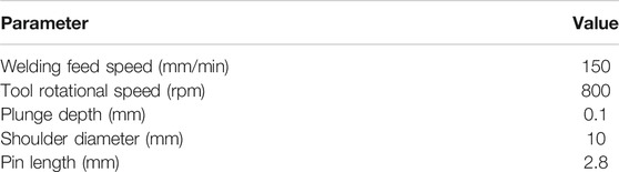
TABLE 2. Welding process parameters of tailor welded blanks.
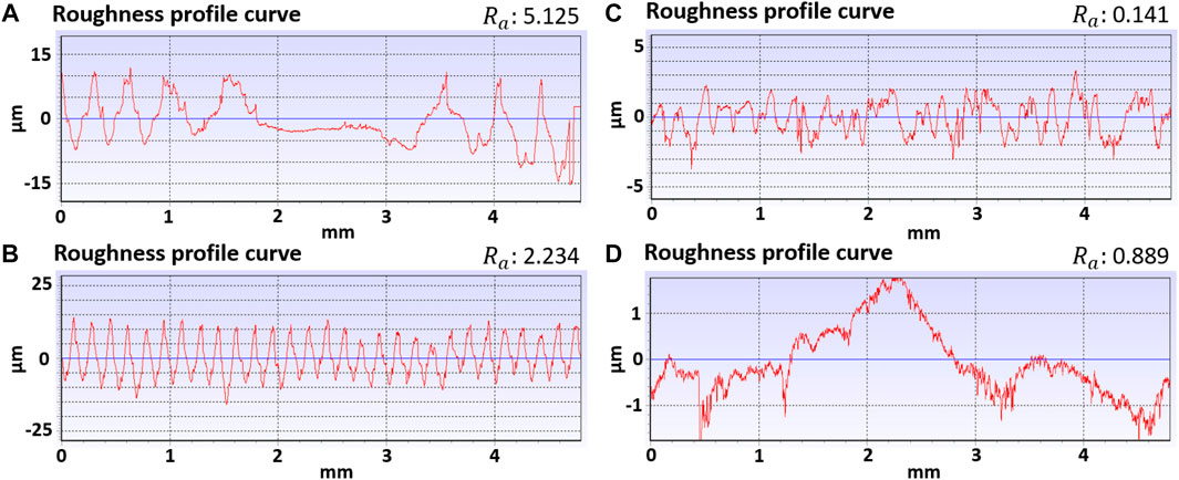
FIGURE 2. Original surface roughness value of the tailor welded blank: (A) roughness of the weld along the welding direction, (B) roughness of the weld perpendicular to the welding direction, (C) roughness of the based material along the welding direction, (D) roughness of the based material perpendicular to the welding direction.
In this study, spinning experiments with tailor welded blanks were carried out by a spin machine PS-CNCSXY1500HD with double rollers, as shown in Figure 3. In the spinning, the roller attack angle is symmetrically set at 45°. To make the tailor welded blank rotate synchronously with the mandrel, a fixed die matched with the fixed end of the mandrel is designed and manufactured, which is connected to the tailstock of the spinning machine. Under the thrust of the hydraulic cylinder of the spinning machine, the tailstock is driven to press the fixed die to fix the tailor welded blank, and make it rotate synchronously with the mandrel. In addition, the forming profiles of spun parts are obtained by a handheld three-dimensional laser scanner based on reverse engineering in the study.
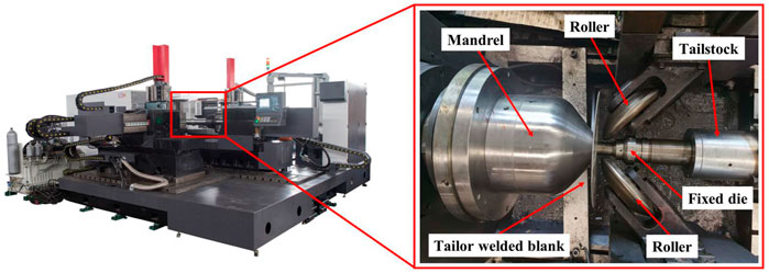
FIGURE 3. Experimental spin machine and setup.
In order to determine the effects of process parameters on spinning with tailor welded blanks, the main spinning process parameters are given in Table 3. The spinning process parameters of the standard experimental group are as follows: the roller nose radius of 6 mm, double roller, the roller attack angle of 45°, the spinning clearance of 1.5 mm, the constant angular velocity of 300 rpm, the installation method of tailor welded blanks (the upper surface of tailor welded blanks is spun by rollers), the lubrication condition of drawing oil, and room temperature. And the other spinning experimental groups with tailor welded blanks were carried out based on the spinning process parameters in Table 3. During the spinning, the surfaces of the tailor welded blank, mandrel, and roller were all coated with liquid drawing oil as lubricant.
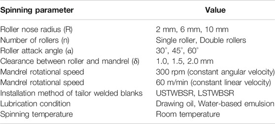
TABLE 3. Experimental conditions of spinning with tailor welded blanks.
The roller nose radius plays an important role in spinning. To study the effect of the roller nose radius in spinning with tailor welded blanks, the roller nose radiuses of 2 mm, 6 mm, and 10 mm were tried, respectively. Forming results are shown in Figure 4A and it can be seen from the top view of spun parts that the weld torsion angle increased from 13° to 15° with the increase of the roller nose radius. The reason is that with the increase of the roller nose radius, the contact area of the roller increases so that the material flow becomes more significant. It can be also seen from the oblique view of spun parts that the surface of spun part under the roller nose radius of 2 mm was the darkest, while under the roller nose radius of 10 mm, the surface of spun part was the brightest. Small roller nose radius leads to more obvious spinning corrugations on the surface of spun parts in spinning, which will result in a worse surface roughness value. As shown in Figure 4B, with the increase of the roller nose radius, the surface roughness values of the parent material and weld decreased rapidly along the longitude direction of spun parts. And the surface roughness values of the parent material and weld along the latitude direction of spun parts had no significant difference with the increase of the roller nose radius. Furthermore, forming profiles of spun parts were exhibited in Figure 4C. Comparing with the forming profiles of spun parts under different roller nose radii, there were little differences on the forming height and radius. But it can be observed that under the roller nose radius of 6 mm, the forming profile of the spun part fitted the mandrel best, while under the roller nose radius of 2 and 10 mm, the swelling defect appeared on the small end of spun parts. And under the roller nose radius of 10 mm, the swelling defect was the most obvious.
FIGURE 4. Experimental results: (A) top and oblique views of spun parts under the roller nose radius of (a) R = 2 mm, (b) R = 6 mm, and (c) R = 10 mm; (B) surface roughnesses of spun parts and (C) forming profile of spun parts.
To explore the effect of the number of rollers in spinning forming with tailor welded blanks, single roller spinning experiment and double rollers spinning experiment was performed, respectively. The experimental results show that the weld torsion angle of spun parts with double rollers spinning was larger than that with single roller spinning, as shown in Figure 5A. This is attributed to the fact that compared with the single roller spinning, the material flow in double rollers spinning is more significant. From the oblique view of spun parts (Figure 5A), the surface gloss of spun parts is almost the same. According to Figure 5B, it can be found that with the increase of the number of rollers, the surface roughness value of the parent material along the longitude direction of spun parts decreased slightly, which is because the contact frequency that the material at the same position is spun by the roller increases in double rollers spinning, resulting in the reduction of the spinning corrugations. However, the surface roughness values of the weld along the longitude direction of spun parts had no significant difference under different numbers of roller. Likewise, due to the generation of spinning corrugations and the increase of the roller contact, the surface roughness values of the parent material and weld along the latitude direction of spun parts in spinning increased slightly. From Figure 5C, it can be intuitively seen that under the double rollers spinning, the forming profile of the spun part fitted the mandrel ideally, while was worse under the single roller spinning, and the swelling defect also appeared on the small end of spun parts. Forming height and radius were basically the same. Therefore, the double rollers spinning is more beneficial to obtain excellent profile accuracy in spinning forming of tailor welded blanks.
FIGURE 5. Experimental results: (A) top and oblique views of spun parts under the rollers number of (a) n = 1, (b) n = 2; (B) surface roughnesses of spun parts and (C) forming profile of spun parts.
The roller attack angle is one of the most important process parameters for spinning forming, not only affecting the forming accuracy of spun parts, but also affecting the surface roughness of spun parts. In this study, the roller attack angles of 30°, 45°, and 60° were tried, respectively. Figure 6A showed the spinning experimental results under different roller attack angles. Under the roller attack angle of 30° and 60°, the weld torsion angles were significantly larger, which can reach 20° and 19°, respectively. However, the weld torsion angle under the roller attack angle of 45° was only 14°. Since the roller contact area increases under the roller attack angle of 30° and 60° compared with the roller attack angle of 45°, this led to the significant material flow during spinning. At the same time, the surface gloss of spun parts under the roller attack angle of 60° also was the brightest, but the fracture defect (Figures 6A–C) appeared on the circumferential and radial direction of spun parts and the flange inclined to the roller side. This is because that the radial tensile stress exerted by rollers significantly increases under the roller attack angle of 60°. As shown in Figure 6B, the surface roughness values of the parent material and weld along the longitude and latitude direction of spun parts overall decreased gradually with the increase of the roller attack angle from 30° to 60°. Besides, it can be observed from Figure 6C that under the roller attack angle of 30° and 45°, the forming profile of spun parts fitted the mandrel ideally, and the forming height and radius were basically the same. While, under the roller attack angle of 60°, the forming profile of spun parts cannot match well with the mandrel.
FIGURE 6. Experimental results: (A) top and oblique views of spun parts under the roller attack angle of (a) α = 30°, (b) α = 45°, and (c) α = 60°; (B) surface roughnesses of spun parts and (C) forming profile of spun parts.
The spinning clearance has a significant effect on spinning. To study the effect of the spinning clearance on spinning with tailor welded blanks, under the spinning clearance of 1.0, 1.5, and 2.0 mm, the spinning experiments were carried out, respectively. Forming results were shown in Figure 7A. With the decrease of the spinning clearance, the weld torsion angles significantly increased. The weld torsion angle was 28° and the serious profile distortion occurred on the spun part when the spinning clearance was set to 1.0 mm. As shown in Figure 7A, the heavy swelling defect appeared on the small end of spun parts, which is caused by the heavy backflow of the material. In addition, it can be found that with the decrease of the spinning clearance, the surface gloss of spun parts was improving, which was in agreement with the surface roughness values of Figure 7B. The surface roughness values of the weld along the longitude and latitude direction of spun parts significantly decreased with the decrease of the spinning clearance. And the surface roughness values of the parent material along the longitude and latitude direction of spun parts slightly decreased with the decrease of the spinning clearance. This is because small spinning clearance brings the significant material flow, which leads to the decrease of spinning corrugations. Furthermore, it can be found from Figure 7C that under the spinning clearance of 2.0 mm, the forming profile of spun parts fitted the mandrel less well, while under the spinning clearance of 1.5 mm, the forming profile of spun parts matched well with the mandrel. And the forming height and radius were almost the same under the spinning clearance of 1.5 and 2.0 mm. This was especially true under the spinning clearance of 1.0 mm, where the forming height was the highest, but the heavy swelling defect appeared on the small end of spun parts.
FIGURE 7. Experimental results: (A) top and oblique views of spun parts under the spinning clearance of (a) δ = 1.0 mm, (b) δ = 1.5 mm, and (c) δ = 2.0 mm; (B) surface roughnesses of spun parts and (C) forming profile of spun parts.
To study the effect of the mandrel rotational speed on spinning with tailor welded blanks, the spinning experiments using the constant angular velocity and constant linear velocity were considered and performed, respectively, in this study. The forming results were shown in Figure 8A. According to the spinning experimental results, there was a little difference on the weld torsion angle under different mandrel rotational speeds. Through observation, the surface gloss of spun parts (Figures 8A,B) under the constant linear velocity was brighter. As shown in Figure 8B, the surface roughness values of the parent material and weld along the longitude and latitude direction of spun parts under the constant linear velocity is all smaller than these under the constant angular velocity. Because the constant linear velocity was used to effectively ensure that the contact speed between the roller and the tailor welded blank is unchanged, this leads to the even spinning corrugations. Furthermore, forming profiles were exhibited in Figure 8C. Under different mandrel rotational speeds, the forming profiles fitted the mandrel well. Forming height and radius of spun parts under the constant linear velocity were a little larger than these under the constant angular velocity. Therefore, the constant linear velocity in spinning forming with tailor welded blanks is helpful to improve the surface quality and forming ability of spun parts.
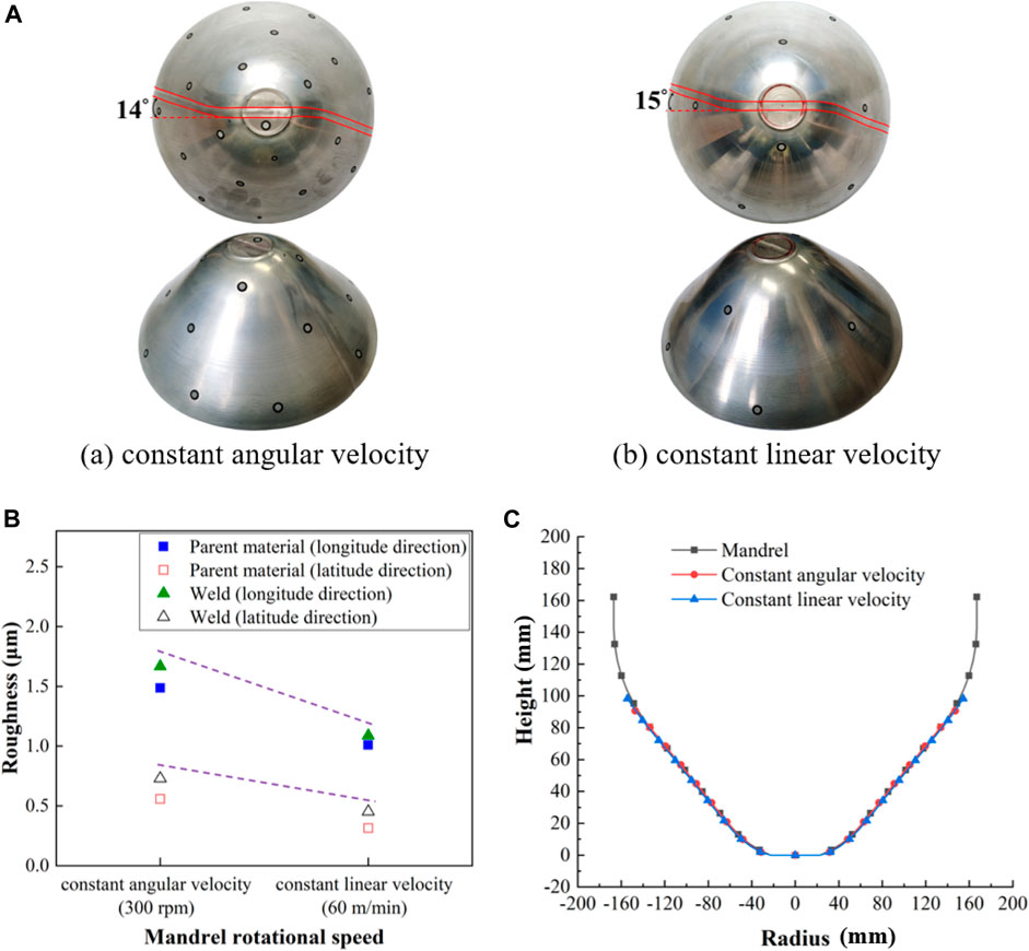
FIGURE 8. Experimental results: (A) top and oblique views of spun parts under (a) constant angular velocity and (b) constant linear velocity; (B) surface roughnesses of spun parts and (C) forming profile of spun parts.
As is known, due to the difference between the upper and lower surface of tailor welded blanks produced by FSW, there are two installation methods of tailor welded blanks in spinning: one is that the upper surface of tailor welded blanks is spun by rollers (USTWBSR) and the other is that the lower surface of tailor welded blanks is spun by rollers (LSTWBSR), as shown in Figure 9. Therefore, the effect of two installation methods of tailor welded blanks on spinning of the thin-walled curved surface parts is studied, respectively. Figure 10A showed the spinning experimental results under two installation methods of tailor welded blanks. The weld torsion angle was larger, i.e., 23° when the installation method of tailor welded blanks was the LSTWBSR, which indicated that the installation method of the LSTWBSR is conducive to the material flow in spinning with tailor welded blanks. In addition, in light of Figure 10B, the surface roughness value of the weld along the longitude direction of spun parts was smaller when the installation method of tailor welded blanks was the LSTWBSR, but along the latitude direction of spun parts, the surface roughness value of the weld was larger. Moreover, the surface roughness values of the parent material along the longitude and latitude direction of spun parts were smaller when the installation method of tailor welded blanks was the LSTWBSR. These differences may be due to the asymmetry of weld geometry. Besides, it can be concluded from Figure 10C that under the installation method of the USTWBSR, the forming profile fitted the mandrel well. The forming height and radius were larger when the LSTWBSR was used as the installation method of tailor welded blanks.
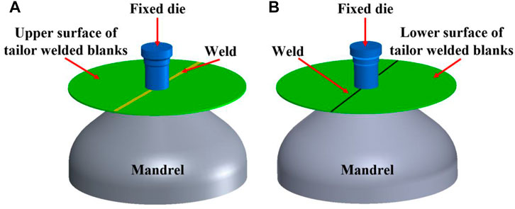
FIGURE 9. Installation method of tailor welded blanks: (A) USTWBSR; (B) LSTWBSR.
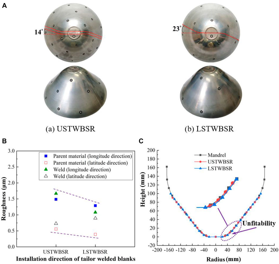
FIGURE 10. Experimental results: (A) top and oblique views of spun parts under the installation method of tailor welded blanks of (a) USTWBSR and (b) LSTWBSR; (B) surface roughnesses of spun parts and (C) forming profile of spun parts.
Different lubrication conditions may affect the spinning of tailor welded blanks. To study the effect of lubrication conditions on spinning, the spinning experiments using the drawing oil and the water-based emulsion were carried out, respectively. The spinning experimental results indicated that the lubrication conditions had little difference on the weld torsion angle, as shown in Figure 11A. But compared with the lubrication condition of the water-based emulsion, the surface gloss of spun parts was brighter using the drawing oil in spinning. This is because the drawing oil effectively prevents the surface of spun parts from oxidizing. In addition, using the lubrication conditions of the drawing oil and the water-based emulsion, there is little effect on the surface roughness of spun parts, as shown in Figure 11B. Further, according to Figure 11C, under different lubrication conditions, the forming profile fitted the mandrel well. When compared with the lubrication condition of the drawing oil, the forming height and radius of spun parts were larger when the water-based emulsion was used in spinning. Therefore, these results showed that the lubrication conditions have no obvious effect on the weld torsion angles of spun parts in spinning with tailor welded blanks, but a little effect on the surface quality and forming ability of spun parts.
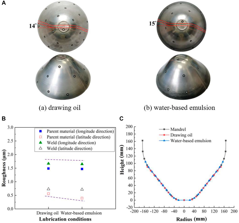
FIGURE 11. Experimental results: (A) top and oblique views of spun parts under the lubrication conditions of (a) drawing oil and (b) water-based emulsion; (B) surface roughnesses of spun parts and (C) forming profile of spun parts.
In this study, spinning experiments of thin-walled curved surface parts using 2195 Al-Li alloy tailor welded blanks produced by friction stir welding from metal scraps were conducted. The effects of process parameters on spinning forming of thin-walled curved surface parts were systematically investigated. From the results obtained in this investigation, the following conclusions can be drawn:
1) The roller attack angle, the spinning clearance, and the installation method of tailor welded blanks have the most significant effect on the weld torsion angle. In addition, the weld torsion angle increases gradually with the increase of the roller nose radius, while with the increase of the spinning clearance, the weld torsion angle decreases significantly.
2) After spinning, along the longitude direction of spun parts, the surface roughnesses of the parent material and weld have been greatly improved under the roller nose radius of 10 mm, the spinning clearance of 1.0 mm, the constant linear velocity, and the installation method of tailor welded blanks of the LSTWBSR, respectively. In addition, the process parameters have little significant effect on the surface roughness along the latitude direction of spun parts.
3) It can be concluded that under these forming parameters (the roller nose radius of 6 mm, the double rollers spinning, the roller attack angle of 30° and 45°, the spinning clearance of 1.5 mm, and the installation method of the USTWBSR, respectively), the forming profiles of spun parts fitted the mandrel well. The mandrel rotational speeds and the lubrication conditions have no effect on forming profiles in this study. When the roller attack angle is too large or the spinning clearance is too small, the target part cannot be spun.
The original contributions presented in the study are included in the article/Supplementary Material, further inquiries can be directed to the corresponding authors.
HZ and MZ put forward ideas, conducted experimental investigation, and wrote the manuscript. ZZ polished the language. RL, WL, and YL contributed with revision and proofreading. MZ and ZZ provided the funding. All authors have read and approved the article for publication.
The authors acknowledge the funding support from the National Science Fund for Distinguished Young Scholars of China (Project 51625505), the National Key R&D Program of China (Project 2020YFA0711100), the National Natural Science Foundation of China (Project U1937203 and Project U1910213), and the Natural Science Basic Research Plan in Shaanxi Province of China (Project 2020JQ-166).
The authors declare that the research was conducted in the absence of any commercial or financial relationships that could be construed as a potential conflict of interest.
All claims expressed in this article are solely those of the authors and do not necessarily represent those of their affiliated organizations, or those of the publisher, the editors and the reviewers. Any product that may be evaluated in this article, or claim that may be made by its manufacturer, is not guaranteed or endorsed by the publisher.
Ahmetoglu, M. A., Brouwers, D., Shulkin, L., Taupin, L., Kinzel, G. L., and Altan, T. (1995). Deep Drawing of Round Cups from Tailor-Welded Blanks. J. Mater. Process. Technol. 53 (3-4), 684–694. doi:10.1016/0924-0136(94)01767-u
Amandeep, S., Deepu, P., Ramkumar, J., and Das, M. (2018). A Simulation Based Approach to Realize green Factory from Unit green Manufacturing Processes. J. Clean. Prod. 182, 67–81.
Buffa, G., Baffari, D., Ingarao, G., and Fratini, L. (2020). Uncovering Technological and Environmental Potentials of Aluminum alloy Scraps Recycling through Friction Stir Consolidation. Int. J. Pr Eng. Man-gt 7 (5), 1. doi:10.1007/s40684-019-00159-5
Chang, S. H., Shin, J. M., Heo, Y. M., and Seo, D. G. (2002). Springback Characteristics of the Tailor-Welded Strips in U-Bending. J. Mater. Process. Tech. 130-131 (1), 14–19. doi:10.1016/s0924-0136(02)00792-6
Chu, W.-S., Kim, M.-S., Jang, K.-H., Song, J.-H., Rodrigue, H., Chun, D.-M., et al. (2016). From Design for Manufacturing (DFM) to Manufacturing for Design (MFD) via Hybrid Manufacturing and Smart Factory: a Review and Perspective of Paradigm Shift. Int. J. Precis. Eng. Manuf.-Green Tech. 3 (2), 209–222. doi:10.1007/s40684-016-0028-0
Doley, J. K., and Kore, S. D. (2017). Comparison of Electromagnetic Forming of Friction Stir-Welded Blanks of Dissimilar Material AA 5052-AA 6061 with Conventional Forming Process. Int. J. Adv. Manuf Techn 93 (3), 1–9. doi:10.1007/s00170-017-0793-0
Elshalakany, A. B., Ali, S., Osman, T. A., Megaid, H., and Mokadem, A. E. (2017). An Experimental Investigation of the Formability of Low Carbon Steel Tailor-Welded Blanks of Different Thickness Ratios. Int. J. Adv. Manuf Techn 88 (5), 1–15. doi:10.1007/s00170-016-8874-z
Gao, P. F., Yu, C., Fu, M. W., Xing, L., Zhan, M., and Guo, J. (2021). Formability Enhancement in Hot Spinning of Titanium Alloy Thin-Walled Tube via Prediction and Control of Ductile Fracture. Chin J Aeronaut. doi:10.1016/j.cja.2021.01.002
Gautam, V., and Kumar, D. R. (2017). Experimental and Numerical Investigations on Springback in V-Bending of Tailor-Welded Blanks of Interstitial Free Steel. Proc. Imeche Part. B: J. Eng. Manufacture 1, 1–14. doi:10.1177/0954405416687146
Gautam, V., Raut, V. M., and Kumar, D. R. (2015). Analytical Prediction of Springback in Bending of Tailor-Welded Blanks Incorporating Effect of Anisotropy and weld Zone Properties. Proc. Imeche Part. L. J. Materials: Des. Appl. 0 (0), 1–13.
Han, Z., Li, H., Xu, X., Wang, H., Li, H., and Tao, J. (2020). Crushing Characteristics of aluminum/CFRP/aluminum Hybrid Tubes Prepared by Spinning Forming. Compos. Structures 249, 112551. doi:10.1016/j.compstruct.2020.112551
Hao, Z., Luo, J., Jin, Y., Meng, D., and Zhang, C. (2020). Application of Pre-deformation Rolling in the Welding Heat-Affected Zone of Tailor-Welded Blanks Formed by Deep-Drawing Process. J. Manufacturing Process. 51, 151–160. doi:10.1016/j.jmapro.2020.01.034
Huang, Y., Meng, X., Xie, Y., Wan, L., Lv, Z., Cao, J., et al. (2018). Friction Stir Welding/processing of Polymers and Polymer Matrix Composites. Composites A: Appl. Sci. Manufacturing 105, 235–257. doi:10.1016/j.compositesa.2017.12.005
Li, P. C., and Zhang, H. M. (2014). Application Situation and Development Strategies of green Manufacturing in china's Automobile Industry. Amr 1049-1050, 945–948. doi:10.4028/www.scientific.net/amr.1049-1050.945
Lin, Y. C., Qian, S.-S., Chen, X.-M., Li, X.-H., and Yang, H. (2019). Staggered Spinning of Thin-Walled Hastelloy C-276 Cylindrical Parts: Numerical Simulation and Experimental Investigation. Thin-Walled Structures 140, 466–476. doi:10.1016/j.tws.2019.04.004
Logesh, B., and Balaji, M. (2020). Experimental Investigations to Deploy green Manufacturing through Reduction of Waste Using Lean Tools in Electrical Components Manufacturing Company. Int. J. Pr Eng. Man-gt 8 (3), 1. doi:10.1007/s40684-020-00216-4
Meinders, T., van den Berg, A., and Huétink, J. (2000). Deep Drawing Simulations of Tailored Blanks and Experimental Verification. J. Mater. Process. Tech. 103 (1), 65–73. doi:10.1016/s0924-0136(00)00420-9
Meng, X. C., Huang, Y. X., Cao, J., Shen, J. J., and JorgeSantos., F. dos. (2021). Recent Progress on Control Strategies for Inherent Issues in Friction Stir Welding. PROG. MATER. SCI. 115, 1. doi:10.1016/j.pmatsci.2020.100706
Meng, X., Xu, Z., Huang, Y., Xie, Y., Wang, Y., Wan, L., et al. (2018). Interface Characteristic and Tensile Property of Friction Stir Lap Welding of Dissimilar Aircraft 2060-T8 and 2099-T83 Al-Li Alloys. Int. J. Adv. Manuf Technol. 94, 1253–1261. doi:10.1007/s00170-017-0996-4
Music, O., Allwood, J. M., and Kawai, K. (2010). A Review of the Mechanics of Metal Spinning. J. Mater. Process. Tech. 210 (1), 3–23. doi:10.1016/j.jmatprotec.2009.08.021
Padmanabhan, R., Oliveira, M. C., and Menezes, L. F. (2008). Deep Drawing of Aluminium-Steel Tailor-Welded Blanks. Mater. Des. 29 (1), 154–160. doi:10.1016/j.matdes.2006.11.007
Parente, M., Safdarian, R., Santos, A. D., Loureiro, A., Vilaca, P., and Jorge, R. (2016). A Study on the Formability of Aluminum Tailor Welded Blanks Produced by Friction Stir Welding. Int. J. Adv. Manuf Techn 83 (9-12), 2129–2141. doi:10.1007/s00170-015-7950-0
Silva, M. B., Skjoedt, M., Vilaça, P., Bay, N., and Martins, P. A. F. (2009). Single point Incremental Forming of Tailored Blanks Produced by Friction Stir Welding. J. Mater. Process. Tech. 209 (2), 811–820. doi:10.1016/j.jmatprotec.2008.02.057
Wang, B., Liu, Z., Song, Q., Wan, Y., and Ren, X. (2020). An Approach for Reducing Cutting Energy Consumption with Ultra-high Speed Machining of Super alloy Inconel 718. Int. J. Precis. Eng. Manuf.-Green Tech. 7 (1), 35–51. doi:10.1007/s40684-019-00125-1
Wang, Y., Su, H., Qian, N., Liu, K., Dai, J., Zhao, Z., et al. (2021). Neck-spinning Quality Analysis and Optimization of Process Parameters for Plunger Components: Simulation and Experimental Study. Chin. J. Aeronautics 34 (4), 174–191. doi:10.1016/j.cja.2020.08.040
Wong, C. C., Dean, T. A., and Lin, J. (2003). A Review of Spinning, Shear Forming and Flow Forming Processes. Int. J. Machine Tools Manufacture 43 (14), 1419–1435. doi:10.1016/s0890-6955(03)00172-x
Xie, Y., Meng, X., Wang, F., Jiang, Y., Ma, X., Wan, L., et al. (2021). Insight on Corrosion Behavior of Friction Stir Welded AA2219/AA2195 Joints in Astronautical Engineering. Corrosion Sci. 192, 109800. doi:10.1016/j.corsci.2021.109800
Xu, W. C., Shan, D. B., Yang, G. P., Lu, Y., and Kang, D. C. (2007). Hot Spinning of Cylindrical Workpieces of TA15 Titanium alloy. Rare Met. 26, 255–261.
Yoon, H.-S., Kim, M.-S., Jang, K.-H., and Ahn, S.-H. (2016). Future Perspectives of Sustainable Manufacturing and Applications Based on Research Databases. Int. J. Precis. Eng. Manuf. 17 (9), 1249–1263. doi:10.1007/s12541-016-0150-5
Zhan, M., Guo, J., Fu, M. W., Gao, P. F., Long, H., and Ma, F. (2018). Formability Limits and Process Window Based on Fracture Analysis of 5A02-O Aluminium alloy in Splitting Spinning. J. Mater. Process. Tech. 257, 15–32. doi:10.1016/j.jmatprotec.2018.02.021
Keywords: friction stir welding, tailor welded blanks, thin-walled parts, 2195 Al-Li alloy, spinning
Citation: Zhang H, Zhan M, Zheng Z, Li R, Lyu W and Lei Y (2021) A Systematic Study on the Effects of Process Parameters on Spinning of Thin-Walled Curved Surface Parts With 2195 Al-Li Alloy Tailor Welded Blanks Produced by FSW. Front. Mater. 8:809018. doi: 10.3389/fmats.2021.809018
Received: 04 November 2021; Accepted: 12 November 2021;
Published: 10 December 2021.
Edited by:
Xiangchen Meng, Harbin Institute of Technology, ChinaReviewed by:
Yuming Xie, Harbin Institute of Technology, ChinaCopyright © 2021 Zhang, Zhan, Zheng, Li, Lyu and Lei. This is an open-access article distributed under the terms of the Creative Commons Attribution License (CC BY). The use, distribution or reproduction in other forums is permitted, provided the original author(s) and the copyright owner(s) are credited and that the original publication in this journal is cited, in accordance with accepted academic practice. No use, distribution or reproduction is permitted which does not comply with these terms.
*Correspondence: Mei Zhan, emhhbm1laUBud3B1LmVkdS5jbg==; Zebang Zheng, emViYW5nLnpoZW5nQG53cHUuZWR1LmNu
Disclaimer: All claims expressed in this article are solely those of the authors and do not necessarily represent those of their affiliated organizations, or those of the publisher, the editors and the reviewers. Any product that may be evaluated in this article or claim that may be made by its manufacturer is not guaranteed or endorsed by the publisher.
Research integrity at Frontiers
Learn more about the work of our research integrity team to safeguard the quality of each article we publish.