 Jinxing Li
 Qun Wu
 Kuang Zhang
- Department of Microwave Engineering, Harbin Institute of Technology, Harbin, China
The metasurface-based superoscillatory lens has been demonstrated to be effective in finely tailoring the wavefront of light to generate focal spots beyond the diffraction limit in the far-field that is capable of improving the resolution of the imaging system. In this paper, an ultra-thin (0.055 λ0) metasurface-based superoscillatory lens (SOL) that can generate a sub-diffraction optical needle with a long focal depth is proposed, which is constructed by ultra-thin chiral unit cells containing two metal split-ring resonators (SRR) with a 90° twisted angle difference cladded on both sides of a 1.5 mm-thick dielectric substrate, with a high linear cross-polarized transmission coefficient around 0.9 and full phase control capability at 11 GHz. Full-wave simulation shows that SOL generates a sub-diffraction optical needle within 10.5–11.5 GHz. At the center frequency, the focal depth is 281 mm (10.3 λ0) within 105–386 mm, the full width at half maximum (FWHM) is 18.5 mm (0.68 λ0), about 0.7 times the diffraction limit, generally consistent with the theoretical result. The proposed ultra-thin chiral metasurface-based SOL holds great potential in integrating into practical imaging applications for its simple fabrication, high efficiency, and low-profile advantages.
1 Introduction
Electromagnetic (EM) wave manipulation is an appealing research field for it is one of the key points to push forward the development of science and engineering. A Metasurface is a novel artificial thin two-dimensional artificial material consisting of subwavelength elements, which provides a powerful platform to manipulate the EM wave with high degrees of freedom (Holloway et al., 2012; Yu et al., 2013; Yu and Capasso, 2014). Thanks to the years of painstaking research of scientists, many great achievements have been obtained, such as orbital angular momentum (OAM) beam generators (Pu et al., 2015; Bi et al., 2018; Zhang et al., 2018; Wang Y. et al., 2020), vector vortex beam generators (Yue et al., 2016; Zuo et al., 2018; Zhuang et al., 2019; Bao et al., 2020), holograms (Zheng et al., 2015; Wang et al., 2018; Wang et al., 2019; Wang Z. et al., 2020; Ding et al., 2020), optical computation (Lin et al., 2018; Li et al., 2019; Abdollahramezani et al., 2020; Lou et al., 2020; Qian et al., 2020), reconfigurable metasurfaces (Ratni et al., 2018; Feng et al., 2020a; Feng et al., 2020b; Ratni et al., 2020; De Lustrac et al., 2021; Popov et al., 2021), multifunctional metasurfaces (Yuan et al., 2019; Zhang et al., 2019; Yuan et al., 2020a; Yuan et al., 2020b; Yuan et al., 2020c; Guan et al., 2020), and superoscillatory lens (Huang et al., 2014; Tang et al., 2015; Qin et al., 2017; Li et al., 2018; Li et al., 2021), etc. Besides, there are still many potential theories and applications that need to be unveiled and exploited.
Tailoring the wavefront is one of the typical applications of a metasurface (Yu et al., 2011; Yu et al., 2013), which is realized by arraying subwavelength elements with different phase and magnitude responses into a special layout. Compared to conventional optical devices, the metasurface modulates phase by subwavelength elements with abrupt phase, but the latter modulates phase through phase accumulation along the optical path, as a result, the profile of the metasurface can be greatly reduced. The key to tailoring the wavefront is to design subwavelength unit cells capable of full phase control. Up to now, abundant metasurfaces have been proposed to tailor the wavefront, they are commonly made of nano dielectric rods or dielectric and metal composites. For the latter, to enhance the transmittance and capability of phase control, unit cells commonly have to be the multilayer type in order to introduce both electric and magnetic resonance (Li et al., 2013; Luo et al., 2017; Zhang et al., 2019; Guan et al., 2020). Among them, chiral metasurfaces are typically applied to polarization conversion and wavefront tailoring (Cong et al., 2013; Grady et al., 2013; Ji et al., 2019; Xu et al., 2019; Fan and Cheng, 2020), a common similarity of them is that a linear polarization incident wave can be transmitted and converted into its orthogonal polarization, but its orthogonal polarization incident wave will be reflected mostly. This is related to their special tri-layer structure, where the outside layers are the same orthogonal structures and the middle layer is a resonator, which behaves as a Fabry-Perot cavity and thus leads to a strong chirality (Grady et al., 2013). For the linear cross-polarized wave transmitted by an arbitrary scatterer, its transmission magnitude will remain unchanged and the phase flips a π if the scatterer is mirrored. Taking advantage of this characteristic, we can design chiral unit cells whose phase can be controlled within a 0-π range, through mirror transformation, the phase within a π-2π range is easily obtained. Therefore, the difficulty of phase control is reduced by half, which provides advantages to optimize unit cells comprehensively, such as improving efficiency, bandwidth, or reducing structural complexity, etc.
Superoscillation is a counter-intuitive phenomenon in which band-limited function can contain local oscillations faster than its fastest Fourier components (Berry and Popescu, 2006; Ferreira and Kempf, 2006). In optical application, it provides a theory to generate arbitrary small-size focal spots in the far-field, which can breakthrough the diffraction limit and greatly enhance the imaging resolution and detect sensitivity. But there are still some obstacles that hinder the practical application of superoscillation, one of the most serious problems is the restriction between the main lobe and sidelobe, the smaller the focal spot, the stronger the sidelobe and the weaker the main lobe, which will deteriorate the quality of imaging, as a result, an appropriate trade-off must be selected according to reality (Huang et al., 2018; Chen et al., 2019). There are many superoscillatory lenses (SOLs) that have been proposed, they can form focal spots beyond the diffraction limit, and have potential in improving resolution in the imaging system.
In this paper, we propose a high transmission ultra-thin chiral unit cell consisting of two identical metal split-ring resonators (SRR) with a 90° twisted angle difference cladded on a 1.5 mm-thick (0.055 λ0) dielectric substrate. It performs polarization conversion with high transmittance around 0.9 and full phase control of transmitted linear cross-polarized waves. Compared to typical tri-layer chiral metasurfaces, the proposed double-layered metasurface has a lower profile and is easier to fabricate, which is conducive to practical applications. Based on the proposed chiral unit cell, an SOL is designed to generate a sub-diffraction optical needle with a long focal depth within 10.5–11.5 GHz, whose operation schematic diagram is illustrated in Figure 1A. Full-wave simulation results show that the SOL generates an optical needle at 11 GHz with a focal depth of 281 mm within 105–386 mm, and the full width at half maximum (FWHM) is 18.5 mm (0.68 λ0) at the focal plane, about 0.7 times the diffraction limit, close to the theoretical results. The proposed ultra-thin transmissive chiral metasurface holds great potential to be integrated into practical communication and imaging systems, for its advantages of low profile, simple structure, and high efficiency.
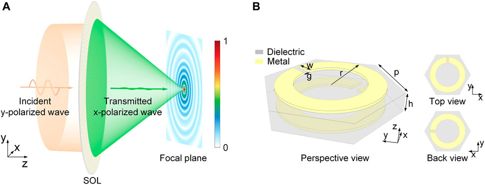
FIGURE 1. (A) Schematic diagram of the proposed superoscillatory lens (SOL). (B) Geometric structure diagram of the proposed chiral structure.
2 Design Principles of SOL
2.1 Mirror Transformation Method
As shown in Figure 2A, we assume there is an arbitrary shape planar scatterer that lies in the xy plane with a transmission Jones matrix Txy as
where txx and tyx (tyy and txy) are co- and cross-polarized transmission coefficients under the x (y) polarization wave incident,
where
where M is the mirror transformation matrix, and + and−represent the mirror along the x and y axes, respectively. Combining the above equations, the relation between Txy and
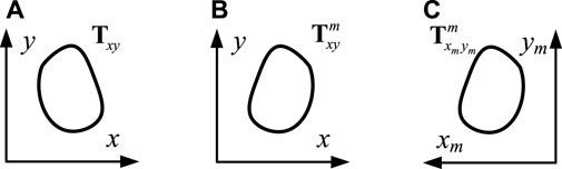
FIGURE 2. (A) Arbitrary shape planar scatterer in the xy plane. (B) Y-axis mirrored scatterer in the xy plane. (C) Y-axis mirrored scatterer in the xmym plane.
Through the above derivation, the relationship between Txy and
2.2 Design of Chiral Unit Cell
According to the above conclusion, achieving full phase control of transmitted linear cross-polarized waves is easier. As mentioned before, transmissive chiral metasurfaces are typically tri-layer metal structures that introduce Fabry-Perot resonance to greatly enhance the chirality of the whole structure. Besides, many double-layer chiral metasurfaces (Han et al., 2011; Huang et al., 2012; Shi et al., 2013; Bokhari and Cheema, 2021) have been proposed, but they are incapable of phase control. Theoretically, it is possible to achieve full phase control using a double-layer structure by combining mirror transformation, here we design a double-layer chiral unit cell capable of phase control. As shown in Figure 1B, the designed chiral structure unit cell is placed in a uniform hexagonal lattice with a side length of p = 5.5 mm, consisting of two identical metal SRRs with a 90° orientation angle difference spaced by a low loss F4BM350 dielectric substrate (εr = 3.5, tan δ = 0.001) with a thickness of h = 1.5 mm (0.055 λ0); the outer ring radius, gap width, and ring width of SRR is r, g, and w, respectively.
The simulation is conducted by Computer Simulation Technology (CST) Microwave Studio, using the unit cell boundary condition to calculate the propagation characteristic of the unit cell through the Floquet model. The simulation model of the hexagonal lattice is shown in Figure 3, a rectangle cut-off window is applied to truncate the infinite periodic, which can preserve the periodic feature of the hexagonal lattice under the unit cell boundary condition in CST. The length and width of the cut-off window are 3p and
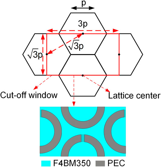
FIGURE 3. The top view of the simulation model of unit cells in a uniform hexagonal lattice.
The propagation schematic diagram of the proposed chiral structure is shown in Figure 4A, when the incident wave propagates along the +z direction, the incident y polarization wave can be transmitted and twisted into an x polarization wave while the incident x polarization wave will be reflected. The working principle of this chiral structure is similar to that in Huang et al. (2012). When propagating along the +z direction (forward propagation), the y polarization wave can excite a fundamental magnetic resonance on the first SRR, which leads to strong cross-coupling between two SRRs. On the contrary, the x polarization wave cannot excite fundamental magnetic resonance due to its orientation, leading to a strong reflection. When the incident wave propagates along the −z direction (backward propagation), according to symmetry and reciprocity, the phenomenon is opposite to that of the forward propagation. The simulated results of the forward and backward propagation are shown in Figure 4A, it is clear that when forward (backward) propagation occurs, around 11 GHz, the incident y (x) polarization wave is mostly transmitted and twisted into an x (y) polarization wave, but the incident x (y) polarization is hardly transmitted, indicating that the unit cell exhibits asymmetric transmission characteristics. The asymmetry transmission parameter (ATP) Δy = |txy|2 − |tyx|2 = − Δx can be calculated to evaluate the strength of the asymmetric transmission effect, for the forward propagation, it is obvious that tyx is almost zero in the entire band, but tyx is higher than 0.9 within 10.3–11.8 GHz; the corresponding Δy is higher than 0.8, on the contrary, when backward propagation occurs, where the Δx is higher than 0.8. The simulated results indicate that the asymmetric transmission effect is quite strong within 10.3–11.8 GHz.
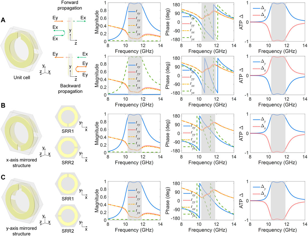
FIGURE 4. (A) Asymmetric propagation schematic of unit cell (parameters: r = 4.2 mm, w = 1.4 mm, g = 0.6 mm) and its corresponding simulated results and asymmetry transmission parameter (ATP) results, the gray region is the band whose |txy| or |tyx| is over 0.9. (B) X-axis and (C) y-axis mirrored structures and their forward propagation results and ATP results.
Besides, as mentioned before, the phase of the transmitted linear cross-polarized wave will flip a π after mirror transformation, simulations are conducted to demonstrate it, here the unit cell in Figure 4A is mirrored along x and y axes, respectively, whose mirrored counterparts are shown in Figures 3B,C. Their forward propagation results are consistent with the theoretical prediction, the results of Figures 4B,C are the same. Compared to the forward propagation results shown in Figure 4A, txx, tyy, and the ATP results are unchanged, but the phases of txy and tyx both flip a π while the magnitude and dispersion remain unchanged, demonstrating that the conclusion derived before is correct.
Through carefully optimizing the structure parameters r, g, and w, the phase of txy can be tuned within the 0-π range while magnitude can stay around 0.9 for the forward propagation. Through mirror transformation, the phase in another range can be easily obtained without additional simulation. The obtained results of the optimized unit cells are shown in Figure 5, where ϕxy and |txy| are the simulated phase and magnitude result of optimized unit cells, respectively, and
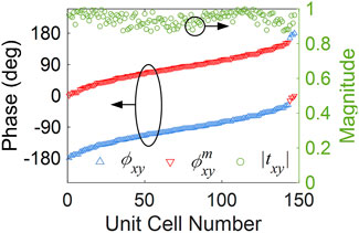
FIGURE 5. The optimized unit cells’ phase and magnitude results of txy at 11 GHz.
2.3 Design of the SOL
To construct an SOL, a complex amplitude profile with special spatial frequency spectrum distribution needs to be appropriately designed. Yet, the abstruse mathematical theories hidden behind superoscillation are still mysterious, consequently, the complex amplitude profile of SOL is commonly calculated through optimization algorithms. However, many design methods have been proposed, which are comprehensively summarized in Chen et al. (2019). Here, we design a phase-only profile combining a focal phase and a binary additional phase to generate a superoscillatory optical needle in the far-field from 100 to 300 mm. The ideal parabolic focal phase profile follows
where the λ0 is the wavelength in free space, F is the focal length, r is the position distance from the origin (0, 0), r2 = x2 + y2, (x, y) is the coordinate on the planar lens, and φi is an arbitrary initial phase. An optimizable binary additional phase φbi is imposed to focal phase profile φFocal to adjust the spatial frequency components of the propagating wave, which can form sub-diffraction focal spots in the far-field, thus, the phase of SOL is φSOL = φFocal + φbi. The binary phase is coded into a series that only contains “0” or “1,” where “0” and “1” represent a phase of 0 and π, respectively. To predict the diffraction field distribution excited by SOL, the phase φSOL is substituted into a scalar Rayleigh-Sommerfeld diffraction integral, which follows
where U (ξ, η, z) is the complex optical field at (ξ, η, z) point, k is the wave vector in free space, R is the distance between the source point (x, y, 0) and field point, and R2 = (x − ξ)2 + (y − η)2 + z2. Each unit cell of the metasurface is regarded as an ideal point source with complex amplitude, and their total interference field in space is regarded as the theoretical result of the metasurface. The phase profile is adjusted according to the feedback of calculated field results; appropriate results are obtained through iterative optimization. Here, the genetic algorithm (GA) is used to optimize the φSOL to generate a sub-diffraction optical needle in the far-field; the sidelobe, focal spot size, focal depth, and intensity flatness of the focal region are the main evaluated goals for optimization. The designed lens has a radius of 200 mm, containing 1,321 unit cells arrayed into a 21 concentric ring layout (including origin). The optimized one-dimension phase results of φFocal, φbi, and φSOL are shown in Figure 6. After iterative optimization, the design frequency is 11 GHz, the focal length F = 175 mm, φi = 90°, and the optimized binary phase is “010101010101011000000” at corresponding concentric rings. In addition, to show the improvement of the designed SOL, a lens-imposed ideal focal phase profile of 200 mm is designed and simulated.
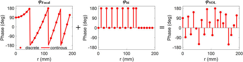
FIGURE 6. The optimized phase profile of SOL at 11 GHz.
3 Results and Discussion
The theoretical calculation and full-wave simulation results at 11 GHz of the designed lens with 200 mm focal length (marked as “lens” here) and SOL are shown in Figure 6, where the full-wave simulation is solved by Lumerical FDTD.
From Figures 7A,B, we can see that the theoretical calculation and simulated results are highly consistent for the lens, but for SOL, they are generally similar but slightly different. According to the results depicted in Figures 7A,C, for the lens, both the theoretical and simulated focal length is around 200 mm with a focal depth of 82 mm within 160–242 mm (range of normalized intensity above 0.7, and the dip in focal region is included). For the SOL, the theoretical normalized field intensity result along the optical axis is quite uniform, the focal depth is 304 mm (11.1 λ0) within 62–362 mm, but the simulated result has two dips at z = 60, 200 mm, the focal depth is 281 mm (10.3 λ0) within 105–386 mm. According to the results shown in Figures 7B,D, the theoretical results of the lens and SOL are perfect, circular, and symmetric, whose sidelobes are uniform concentric rings surrounding the circular focal spot, but the simulated results are only slightly uniform, especially for the SOL. The theoretical and simulated FWHM is 25.5 mm (0.94 λ0), 26.6 mm (0.98 λ0) for the lens, and 19.5 (0.72 λ0), 18.5 mm (0.68 λ0) for SOL, respectively, here the simulated FWHM of the lens is considered as the diffraction limit. The theoretical and simulated maximum sidelobe behind the focal spot is 0.17, 0.23 for the lens, and 0.41, 0.68. Comparing the simulated performance of the lens and SOL, the FWHM of SOL is 0.7 times that of the lens, but the sidelobe of SOL is 2.96 times that of the lens.
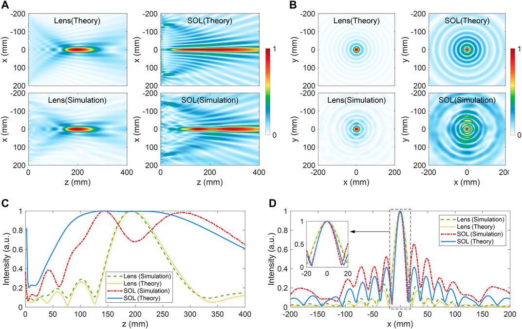
FIGURE 7. Theoretical calculated and simulated normalized Ex field distribution in (A) the XZ plane at y = 0 mm and (B) the XY plane at z = 200 mm (11 GHz). Normalized intensity of Ex along (C) the optical axis, and (D) the x-axis at the focal plane, the inset is a partially enlarged view of focal spot intensity.
The difference between theoretical and simulated results is mainly caused by the deviation of the real phase profile from the designed one. Metasurfaces inevitably suffer from the quasi-periodic effect that the real phase of the unit cell in the metasurface deviates from that calculated from the Floquet theory due to the change of layout and neighbor unit cells. For this chiral structure, the coupling between neighbor unit cells cannot be ignored because the SRRs are strong resonators and they are placed nearby, which will increase the quasi-periodic effect. However, the superoscillatory optical field contains subtle features of light that need subtle manipulation of light, which makes it sensitive to the deviation of phase. Therefore, the quasi-periodic effect leads to the simulation result of SOL deviating apparently from the theoretical one. Compared to the theoretical result of SOL, the simulated result exhibits a shorter focal depth, a mild fluctuation of intensity within the focal region, and a smaller FWHM focal spot, but the cost is the increase of the sidelobe. However, the performance of the SOL can be improved closer to that of the design goals through phase profile calibration of the metasurface, which needs complex optimization.
To analyze the working bandwidth of the SOL, the simulated results of SOL within 10.5–11.5 GHz are shown in Figure 8. From the two-dimensional normalized field distribution shown in Figures 8A,B, we can observe that as the frequency increases, a dip appears in the optical axis, and the field at the focal plane becomes nonuniform, especially within 10.9–11.3 GHz where the sidelobes are increased obviously, and the field intensity along the x and y axes is quite different. The normalized field intensity along the x and y axes on the focal plane is shown in Figure 8C, it clearly shows that the field intensity along the y-axis has a smaller FWHM compared to that along the x-axis, but the cost is that the maximum sidelobe is a bit larger. The performance of SOL is concluded in Figure 8D, the focal depth is lengthened as the frequency increases, the FWHM along the y-axis is smaller but the maximum sidelobe is larger, compared to that along the x-axis. The performance of the SOL within 10.5–11.5 GHz still maintains a long focal depth of over 200 mm, and the FWHM of the focal spot is smaller than that of the focal lens, but the maximum sidelobe is larger, which shows that the SOL can generate a sub-diffraction optical needle with a 1 GHz bandwidth within 10.5–11.5 GHz, providing the potential to integrate it into the imaging system to improve the resolution and depth of field. The focusing and transmission efficiencies on the focal plane of the lens and SOL within 10.5–11.5 GHz are also analyzed. The focusing efficiency is the ratio between the power of the focal spot and the source, and the transmission efficiency is the ratio between the power of the focal plane and the source. For the lens, the focusing (transmission) efficiency is generally higher than 30% (50%) in the whole band, whose maximum is 47.5% (71.5%) at 10.6 GHz, indicating that the focal spot occupies a lot of power on the focal plane. In addition, the results demonstrate that the proposed ultra-thin chiral unit cell has high transmission in this band. But for the SOL, the focusing efficiency of SOL is only 0.9–3.4% in the working band while the total efficiency on the focal plane is over 30%, which means that the focal spot occupies little power in the focal plane. The reason for the low focusing efficiency of SOL is that the superoscillatory field is generated through destructive interference in space, therefore, the efficiency is inherently low. Especially, the smaller the focal spot, the weaker the main lobe. The generated focal spot is quite small here, about 0.7 times the diffraction limit, and the smallest focusing efficiency 0.9% is at 11.1 GHz whose corresponding focal spot is the smallest. Due to the focal spot region being too small and the intensity of the main lobe being weakened, the focusing efficiency of SOL is consequently low. The focusing efficiency can be improved by relieving the quasi-periodic effect to make the diffraction distribution get closer to the theoretically designed one.
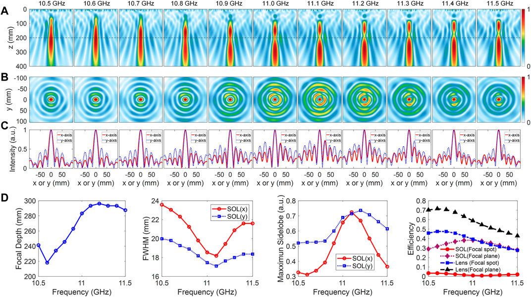
FIGURE 8. Simulated normalized Ex field distribution from 10.5 to 11.5 GHz on (A) the XZ plane at y = 0 mm (dash line is z = 200 mm), (B) the focal plane at z = 200 mm, and (C) along the x and y axes on the focal plane. (D) The focal depth, FWHM, normalized maximum sidelobe along the x and y axes, and focusing and transmission efficiency of SOL and the lens on the focal plane in 10.5–11.5 GHz.
4 Conclusion
In summary, we propose and validate a transmissive ultra-thin (0.055 λ0) chiral unit cell that effectively performs polarization conversion with high transmittance around 0.9 at 11 GHz, which only contains two metal SRRs with the same structure and a 90° twisted angle difference. Through mirror transformation, the phase of transmitted cross-polarized wave can flip a π, assisted by this characteristic, full phase control can be achieved easily. Compared to the previously proposed typical tri-layer chiral structure, the proposed chiral structure exhibits similar transmission characteristics, but it is simplified into a doublet, facilitating cut-down of fabrication costs and reducing the profile, and thus it is beneficial to practical application. An SOL based on the proposed ultra-thin chiral metasurface is designed to form a long focal depth optical needle beyond the diffraction limit. The phase profile of the SOL is optimized by the genetic algorithm; a phase profile that can generate a sub-diffraction optical needle with a long focal depth is selected. Full-wave simulation shows the generation of the sub-diffraction optical needle within 10.5–11.5 GHz, at the center frequency, the designed SOL generates an optical needle with a focal depth of 281 mm (10.3 λ0) within 105–386 mm, the FWHM of the focal spot at z = 200 mm is 18.5 mm (0.68 λ0), 0.7 times the FWHM of the normal focal lens, beyond the diffraction limit. The designed method of combining mirror transformation effectively reduces the task of unit cell design and may enlighten new ways to control the phase. The proposed ultra-thin SOL can effectively improve the imaging performance of resolution and depth of field, which provides a new option for the trend of imaging system integration and miniaturization.
Data Availability Statement
The original contributions presented in the study are included in the article/Supplementary Material, further inquiries can be directed to the corresponding authors.
Author Contributions
KZ, YY, and GY proposed the idea, JL conducted the simulations, JL, GY, YY, QW, and KZ organized and read through the manuscript together.
Funding
This work is supported by the National Natural Science Foundation of China (No. 62171165, 61771172), the Open Project of Guangxi Key Laboratory of Wireless Wideband Communication and Signal Processing, and the Natural Science Foundation of Heilongjiang Province (No. YQ2020F002).
Conflict of Interest
The authors declare that the research was conducted in the absence of any commercial or financial relationships that could be construed as a potential conflict of interest.
Publisher’s Note
All claims expressed in this article are solely those of the authors and do not necessarily represent those of their affiliated organizations, or those of the publisher, the editors and the reviewers. Any product that may be evaluated in this article, or claim that may be made by its manufacturer, is not guaranteed or endorsed by the publisher.
References
Abdollahramezani, S., Hemmatyar, O., and Adibi, A. (2020). Meta-optics for Spatial Optical Analog Computing. Nanophotonics 9, 4075–4095. doi:10.1515/nanoph-2020-0285
Bao, Y., Ni, J., and Qiu, C. W. (2020). A Minimalist Single‐Layer Metasurface for Arbitrary and Full Control of Vector Vortex Beams. Adv. Mater. 32, 1905659–1905668. doi:10.1002/adma.201905659
Berry, M. V., and Popescu, S. (2006). Evolution of Quantum Superoscillations and Optical Superresolution without Evanescent Waves. J. Phys. A: Math. Gen. 39, 6965–6977. doi:10.1088/0305-4470/39/22/011
Bi, F., Ba, Z., and Wang, X. (2018). Metasurface-based Broadband Orbital Angular Momentum Generator in Millimeter Wave Region. Opt. Express 26, 25693. doi:10.1364/oe.26.025693
Bokhari, S. H. A., and Cheema, H. M. (2021). A Bilayered, Broadband, Angularly Robust Chiral Metasurface for Asymmetric Transmission. Antennas Wirel. Propag. Lett. 20, 23–27. doi:10.1109/LAWP.2020.3037045
Chen, G., Wen, Z.-Q., and Qiu, C.-W. (2019). Superoscillation: from Physics to Optical Applications. Light Sci. Appl. 8, 56. doi:10.1038/s41377-019-0163-9
Cong, L., Cao, W., Zhang, X., Tian, Z., Gu, J., Singh, R., et al. (2013). A Perfect Metamaterial Polarization Rotator. Appl. Phys. Lett. 103, 171107. doi:10.1063/1.4826536
De Lustrac, A., Ratni, B., Piau, G.-P., Duval, Y., and Burokur, S. N. (2021). Tri-state Metasurface-Based Electromagnetic Screen with Switchable Reflection, Transmission, and Absorption Functionalities. ACS Appl. Electron. Mater. 3, 1184–1190. doi:10.1021/acsaelm.0c01038
Ding, X., Wang, Z., Hu, G., Liu, J., Zhang, K., Li, H., et al. (2020). Metasurface Holographic Image Projection Based on Mathematical Properties of Fourier Transform. PhotoniX 1, 1–12. doi:10.1186/s43074-020-00016-8
Fan, J., and Cheng, Y. (2020). Broadband High-Efficiency Cross-Polarization Conversion and Multi-Functional Wavefront Manipulation Based on Chiral Structure Metasurface for Terahertz Wave. J. Phys. D: Appl. Phys. 53, 025109. doi:10.1088/1361-6463/ab4d76
Feng, R., Ratni, B., Yi, J., Jiang, Z., Zhang, H., Lustrac, A., et al. (2020a). Flexible Manipulation of Bessel‐Like Beams with a Reconfigurable Metasurface. Adv. Opt. Mater. 8, 2001084–2001110. doi:10.1002/adom.202001084
Feng, R., Ratni, B., Yi, J., Zhang, K., Ding, X., Zhang, H., et al. (2020b). Versatile Airy-Beam Generation Using a 1-Bit Coding Programmable Reflective Metasurface. Phys. Rev. Appl. 14, 1. doi:10.1103/PhysRevApplied.14.014081
Ferreira, P. J. S. G., and Kempf, A. (2006). Superoscillations: Faster Than the Nyquist Rate. IEEE Trans. Signal. Process. 54, 3732–3740. doi:10.1109/TSP.2006.877642
Grady, N. K., Heyes, J. E., Chowdhury, D. R., Zeng, Y., Reiten, M. T., Azad, A. K., et al. (2013). Terahertz Metamaterials for Linear Polarization Conversion and Anomalous Refraction. Science 340, 1304–1307. doi:10.1126/science.1235399
Guan, C., Liu, J., Ding, X., Wang, Z., Zhang, K., Li, H., et al. (2020). Dual-polarized Multiplexed Meta-Holograms Utilizing Coding Metasurface. Nanophotonics 9, 3605–3613. doi:10.1515/nanoph-2020-0237
Han, J., Li, H., Fan, Y., Wei, Z., Wu, C., Cao, Y., et al. (2011). An Ultrathin Twist-Structure Polarization Transformer Based on Fish-Scale Metallic Wires. Appl. Phys. Lett. 98, 151908–151999. doi:10.1063/1.3580608
Holloway, C. L., Kuester, E. F., Gordon, J. A., O'hara, J., Booth, J., and Smith, D. R. (2012). An Overview of the Theory and Applications of Metasurfaces: The Two-Dimensional Equivalents of Metamaterials. IEEE Antennas Propag. Mag. 54, 10–35. doi:10.1109/MAP.2012.6230714
Huang, C., Feng, Y., Zhao, J., Wang, Z., and Jiang, T. (2012). Asymmetric Electromagnetic Wave Transmission of Linear Polarization via Polarization Conversion through Chiral Metamaterial Structures. Phys. Rev. B 85. doi:10.1103/PhysRevB.85.195131
Huang, K., Qin, F., Liu, H., Ye, H., Qiu, C. W., Hong, M., et al. (2018). Planar Diffractive Lenses: Fundamentals, Functionalities, and Applications. Adv. Mater. 30, 1704556. doi:10.1002/adma.201704556
Huang, K., Ye, H., Teng, J., Yeo, S. P., Luk'yanchuk, B., and Qiu, C.-W. (2014). Optimization-free Superoscillatory Lens Using Phase and Amplitude Masks. Laser Photon. Rev. 8, 152–157. doi:10.1002/lpor.201300123
Ji, W., Cai, T., Wang, G., Li, H., Wang, C., Hou, H., et al. (2019). High-efficiency and Ultra-broadband Asymmetric Transmission Metasurface Based on Topologically Coding Optimization Method. Opt. Express 27, 2844. doi:10.1364/oe.27.002844
Li, J., Mengu, D., Luo, Y., Rivenson, Y., and Ozcan, A. (2019). Class-specific Differential Detection in Diffractive Optical Neural Networks Improves Inference Accuracy. Adv. Photon. 1, 1. doi:10.1117/1.ap.1.4.046001
Li, M., Al-Joumayly, M. A., and Behdad, N. (2013). Broadband True-Time-Delay Microwave Lenses Based on Miniaturized Element Frequency Selective Surfaces. IEEE Trans. Antennas Propagat. 61, 1166–1179. doi:10.1109/TAP.2012.2227444
Li, Z., Wang, C., Wang, Y., Lu, X., Guo, Y., Li, X., et al. (2021). Super-oscillatory Metasurface Doublet for Sub-diffraction Focusing with a Large Incident Angle. Opt. Express 29, 9991. doi:10.1364/oe.417884
Li, Z., Zhang, T., Wang, Y., Kong, W., Zhang, J., Huang, Y., et al. (2018). Achromatic Broadband Super-resolution Imaging by Super-oscillatory Metasurface. Laser Photon. Rev. 12, 1800064–1800066. doi:10.1002/lpor.201800064
Lin, X., Rivenson, Y., Yardimci, N. T., Veli, M., Luo, Y., Jarrahi, M., et al. (2018). All-optical Machine Learning Using Diffractive Deep Neural Networks. Science 361, 1004–1008. doi:10.1126/science.aat8084
Lou, Y., Fang, Y., and Ruan, Z. (2020). Optical Computation of Divergence Operation for Vector Fields. Phys. Rev. Appl. 14, 1. doi:10.1103/PhysRevApplied.14.034013
Luo, W., Sun, S., Xu, H. X., He, Q., and Zhou, L. (2017). Transmissive Ultrathin Pancharatnam-Berry Metasurfaces with Nearly 100% Efficiency. Phys. Rev. Appl. 7, 1–8. doi:10.1103/PhysRevApplied.7.044033
Nanfang Yu, N., Genevet, P., Aieta, F., Kats, M. A., Blanchard, R., Aoust, G., et al. (2013). Flat Optics: Controlling Wavefronts with Optical Antenna Metasurfaces. IEEE J. Select. Top. Quan. Electron. 19, 4700423. doi:10.1109/JSTQE.2013.2241399
Popov, V., Ratni, B., Burokur, S. N., and Boust, F. (2021). Non‐Local Reconfigurable Sparse Metasurface: Efficient Near‐Field and Far‐Field Wavefront Manipulations. Adv. Opt. Mater. 9, 2001316–2001411. doi:10.1002/adom.202001316
Pu, M., Li, X., Ma, X., Wang, Y., Zhao, Z., Wang, C., et al. (2015). Catenary Optics for Achromatic Generation of Perfect Optical Angular Momentum. Sci. Adv. 1, 1–7. doi:10.1126/sciadv.1500396
Qian, C., Lin, X., Lin, X., Xu, J., Sun, Y., Li, E., et al. (2020). Performing Optical Logic Operations by a Diffractive Neural Network. Light Sci. Appl. 9, 59. doi:10.1038/s41377-020-0303-2
Qin, F., Huang, K., Wu, J., Teng, J., Qiu, C.-W., and Hong, M. (2017). A Supercritical Lens Optical Label-free Microscopy: Sub-diffraction Resolution and Ultra-long Working Distance. Adv. Mater. 29, 1602721–1602726. doi:10.1002/adma.201602721
Ratni, B., De Lustrac, A., Piau, G.-P., and Burokur, S. N. (2018). Reconfigurable Meta-Mirror for Wavefronts Control: Applications to Microwave Antennas. Opt. Express 26, 2613. doi:10.1364/oe.26.002613
Ratni, B., Wang, Z., Zhang, K., Ding, X., De Lustrac, A., Piau, G.-P., et al. (2020). Dynamically Controlling Spatial Energy Distribution with a Holographic Metamirror for Adaptive Focusing. Phys. Rev. Appl. 13, 1. doi:10.1103/PhysRevApplied.13.034006
Shi, J., Liu, X., Yu, S., Lv, T., Zhu, Z., Feng Ma, H., et al. (2013). Dual-band Asymmetric Transmission of Linear Polarization in Bilayered Chiral Metamaterial. Appl. Phys. Lett. 102, 191905. doi:10.1063/1.4805075
Tang, D., Wang, C., Zhao, Z., Wang, Y., Pu, M., Li, X., et al. (2015). Ultrabroadband Superoscillatory Lens Composed by Plasmonic Metasurfaces for Subdiffraction Light Focusing. Laser Photon. Rev. 9, 713–719. doi:10.1002/lpor.201500182
Wang, Y., Guan, C., Ding, X., Zhang, K., Ratni, B., Burokur, S. N., et al. (2019). Multi-focus Hologram Utilizing Pancharatnam-Berry Phase Elements Based Metamirror. Opt. Lett. 44, 2189. doi:10.1364/ol.44.002189
Wang, Y., Zhang, K., Yuan, Y., Ding, X., Ratni, B., Burokur, S. N., et al. (2020a). Planar Vortex Beam Generator for Circularly Polarized Incidence Based on FSS. IEEE Trans. Antennas Propagat. 68, 1514–1522. doi:10.1109/TAP.2019.2938666
Wang, Z., Ding, X., Zhang, K., Ratni, B., Burokur, S. N., Gu, X., et al. (2018). Huygens Metasurface Holograms with the Modulation of Focal Energy Distribution. Adv. Opt. Mater. 6, 1800121–1800127. doi:10.1002/adom.201800121
Wang, Z., Liu, J., Ding, X., Zhao, W., Zhang, K., Li, H., et al. (2020b). Three-Dimensional Microwave Holography Based on Broadband Huygens' Metasurface. Phys. Rev. Appl. 13, 1. doi:10.1103/PhysRevApplied.13.014033
Xu, H. X., Hu, G., Han, L., Jiang, M., Huang, Y., Li, Y., et al. (2019). Chirality‐Assisted High‐Efficiency Metasurfaces with Independent Control of Phase, Amplitude, and Polarization. Adv. Opt. Mater. 7, 1801479–1801510. doi:10.1002/adom.201801479
Yu, N., and Capasso, F. (2014). Flat Optics with Designer Metasurfaces. Nat. Mater 13, 139–150. doi:10.1038/nmat3839
Yu, N., Genevet, P., Kats, M. A., Aieta, F., Tetienne, J.-P., Capasso, F., et al. (2011). Light Propagation with Phase Discontinuities: Generalized Laws of Reflection and Refraction. Science 334, 333–337. doi:10.1126/science.1210713
Yuan, Y., Chen, S., Ratni, B., Wu, Q., Ding, X., Burokur, S. N., et al. (2020a). Bi-functional Meta-Device with Full Energy Utilization in Co- and Cross-Polarization fields. Appl. Phys. Lett. 117, 171602. doi:10.1063/5.0022989
Yuan, Y., Sun, S., Chen, Y., Zhang, K., Ding, X., Ratni, B., et al. (2020b). A Fully Phase‐Modulated Metasurface as an Energy‐Controllable Circular Polarization Router. Adv. Sci. 7, 2001437–2001438. doi:10.1002/advs.202001437
Yuan, Y., Zhang, K., Ding, X., Ratni, B., Burokur, S. N., and Wu, Q. (2019). Complementary Transmissive Ultra-thin Meta-Deflectors for Broadband Polarization-independent Refractions in the Microwave Region. Photon. Res. 7, 80. doi:10.1364/prj.7.000080
Yuan, Y., Zhang, K., Ratni, B., Song, Q., Ding, X., Wu, Q., et al. (2020c). Independent Phase Modulation for Quadruplex Polarization Channels Enabled by Chirality-Assisted Geometric-phase Metasurfaces. Nat. Commun. 11, 1–9. doi:10.1038/s41467-020-17773-6
Yue, F., Wen, D., Xin, J., Gerardot, B. D., Li, J., and Chen, X. (2016). Vector Vortex Beam Generation with a Single Plasmonic Metasurface. ACS Photon. 3, 1558–1563. doi:10.1021/acsphotonics.6b00392
Zhang, K., Yuan, Y., Ding, X., Ratni, B., Burokur, S. N., and Wu, Q. (2019). High-Efficiency Metalenses with Switchable Functionalities in Microwave Region. ACS Appl. Mater. Inter. 11, 28423–28430. doi:10.1021/acsami.9b07102
Zhang, K., Yuan, Y., Zhang, D., Ding, X., Ratni, B., Burokur, S. N., et al. (2018). Phase-engineered Metalenses to Generate Converging and Non-diffractive Vortex Beam Carrying Orbital Angular Momentum in Microwave Region. Opt. Express 26, 1351. doi:10.1364/oe.26.001351
Zheng, G., Mühlenbernd, H., Kenney, M., Li, G., Zentgraf, T., and Zhang, S. (2015). Metasurface Holograms Reaching 80% Efficiency. Nat. Nanotechnol 10, 308–312. doi:10.1038/nnano.2015.2
Zhuang, Z.-P., Chen, R., Fan, Z.-B., Pang, X.-N., and Dong, J.-W. (2019). High Focusing Efficiency in Subdiffraction Focusing Metalens. Nanophotonics 8, 1279–1289. doi:10.1515/nanoph-2019-0115
Keywords: metasurface, chirality, ultra-thin, polarization conversion, transmission, high efficiency, microwave, optical superoscillation
Citation: Li J, Yang G, Yuan Y, Wu Q and Zhang K (2022) Ultra-Thin Chiral Metasurface-Based Superoscillatory Lens. Front. Mater. 8:806725. doi: 10.3389/fmats.2021.806725
Received: 01 November 2021; Accepted: 26 November 2021;
Published: 07 January 2022.
Edited by:
Wei-Xiang Jiang, Southeast University, ChinaReviewed by:
Weiren Zhu, Shanghai Jiao Tong University, ChinaHui Feng Ma, Southeast University, China
Copyright © 2022 Li, Yang, Yuan, Wu and Zhang. This is an open-access article distributed under the terms of the Creative Commons Attribution License (CC BY). The use, distribution or reproduction in other forums is permitted, provided the original author(s) and the copyright owner(s) are credited and that the original publication in this journal is cited, in accordance with accepted academic practice. No use, distribution or reproduction is permitted which does not comply with these terms.
*Correspondence: Guohui Yang, Z2gueWFuZ0BoaXQuZWR1LmNu; Yueyi Yuan, eXVhbnl1ZXlpQGhpdC5lZHUuY24=; Kuang Zhang, emhhbmdrdWFuZ0BoaXQuZWR1LmNu