 Xinmin Fu
 Ya Fan2†
 Yajuan Han
 Jiafu Wang
95% of researchers rate our articles as excellent or good
Learn more about the work of our research integrity team to safeguard the quality of each article we publish.
Find out more
ORIGINAL RESEARCH article
Front. Mater. , 12 January 2022
Sec. Metamaterials
Volume 8 - 2021 | https://doi.org/10.3389/fmats.2021.806597
This article is part of the Research Topic Multifunctional and Reconfigurable Electromagnetic and Acoustic Metasurfaces View all 9 articles
The integration of the metasurface and antenna has brought new vitality to function integration and performance improvement for metasurfaces. In this study, we propose a radiation-scattering–integrated (RSI) design method of functional metasurfaces by incorporating antenna radiators into the substrates. The antenna radiators can also be considered as a band-stop frequency selective surface (FSS) embedded within the dielectric substrate, which adds up to the degree of freedom (DOF) in tailoring electromagnetic (EM) properties of the substrate. In this way, not only radiation function is added to the metasurfaces but also the original scattering-manipulation function is augmented. As an example, we apply this method to the design of a metasurface that can achieve a high radiation gain in-band and low-RCS out-of-band simultaneously. An antenna array was first designed, which uses circular patches as the radiators. Then, the antenna array was used as the substrate of a typical polarization conversion (PC) metasurface. The circular patch lies between the ground plane and the PC meta-atom, providing optimal electrical substrate thickness for PC at two separate bands. By adjusting structural parameters, the operating band of the antenna array can be made to lie in between the two PC bands. In this way, the metasurface can simultaneously possess high-gain radiation function in-band and high-efficiency PC function for RCS reduction out-of-band. A prototype was fabricated and measured. Both the simulated and measured results show that the metasurface can achieve satisfactory radiation gain in-band and significant RCS reduction out of band. This work provides an alternative method of designing multi-functional metasurfaces, which may find applications in smart skins and others.
Metamaterials have undergone an unprecedented development since its birth. Analogous to conventional materials consisting of molecules or atoms, metamaterials are usually composed of sub-wavelength dielectric or metallic resonators (also called meta-atoms) (Pendry, 2000; Smith et al., 2004; Cheng and Cui, 2006; Wang et al., 2010). Physical properties of metamaterials can be freely engineered by tailoring resonances of meta-atoms (Sihvola, 2007; Hao et al., 2009; Han et al., 2018). Thus, metamaterials have shown unique advantages in manipulating electromagnetic waves. Metasurfaces can be considered as planar metamaterials (Yu et al., 2011; Xu et al., 2013). Due to low profile, easy fabrication, and other advantages, metasurfaces have received significant attention from the academic community in the last decade (Sun et al., 2012; Diaz-Rubio et al., 2017).
The study of metasurfaces initially began with the phase gradient metasurface (PGM) proposed in 2011 (Yu et al., 2011). According to Fermat’s principle, F. Capasso et al. designed a PGM composed of V-shaped meta-atoms. By designing the orientation and opening angle of the unit, the phase response of the meta-atom to electromagnetic waves can be regulated. The V-shaped structural elements with different response phases are arranged periodically according to the phase profile predicted by the theory so that the propagation direction of the electromagnetic wave can be freely controlled. Using metasurfaces, polarization, amplitude, and the phase of the electromagnetic (EM) waves can be controlled by designing the pattern of meta-atoms, adjusting the geometric parameters and loading resistor, etc. (Iriarte Galarregui et al., 2013; Chen et al., 2016; Xu et al., 2016; Diaz-Rubio et al., 2017; Huang et al., 2017; Lv et al., 2020). Later, the ideology and methodology of the antenna design was introduced into the metasurface design, which injects new vitality into the development of metasurfaces (Jiang et al., 2016; Li et al., 2017; Huang and Shen, 2019; Zhang et al., 2020; Wang et al., 2020). Based on the receiver–transmitter antenna design, Peng Xie et al. proposed a metasurface which is capable of linear-to-circular PC (Xie et al., 2019). Two different antenna elements with similar radiation performances and different reflection phases are designed and arranged as the chessboard metasurface so as to integrate the radiation and scattering performances in the same metasurface aperture (Liu et al., 2019).
In the metasurface design, researchers usually focus on the period, structural patterns, and spatial orientations of the meta-atom. A large number of functional metasurfaces have been put forward that were composed with various meta-atom patterns and periodicities. Nevertheless, an important influential factor, the substrate thickness, is neglected and is usually supposed to be with a constant physical size. In fact, the electrical thickness of the substrate can introduce a new degree of freedom (DOF) for the metasurface design. Tailoring the electrical thickness of the substrate will bring new vitality to function integration and performance improvement of functional metasurfaces.
Inspired by this, in this study, we propose a method of designing radiation-scattering–integrated metasurfaces using antenna-embedded substrates. Antenna radiator structures are embedded within the substrate, which can not only be used as an antenna to radiate EM waves but also exhibit band-stop properties. This allows the electrical thickness of the substrate to vary with frequency, which can be tailored deliberately to achieve multiple functions at different bands. As an example, a dual-band PC metasurface with a co-polarization reflection “window” was designed by inserting a circular patch antenna into the substrate of a conventional PC meta-atom. A metasurface with 8 × 8 meta-atoms is constructed by feeding the circular patch with the same amplitude and phase through the feeding network. The metasurface can radiate the EM waves with a high gain in-band. For incident EM waves out of band, the reflected waves will be scattered towards four oblique directions due to scattering cancellation, leading to significant reduction of RCS. A prototype was fabricated and measured. Both the simulated and measured results verify the in-band high-gain and out-band RCS reduction functions. This work provides an alternative way of designing multi-functional metasurfaces.
The traditional reflective metasurface consists of a metal pattern, a dielectric substrate, and a metal back plate. Different patterns of metal structures represent different properties (Modi et al., 2017; Zheng et al., 2015; Zhang et al., 2016). But no matter what kind of structure, the performance and response of the metasurface cannot be separated from the dielectric substrate. In other words, the thickness of the substrate is an important factor affecting the metasurface properties. A common PC meta-atom (Fan et al., 2018; Fu et al., 2021) shown in Figure 1A is employed to specify the importance of the substrate thickness. The biarc meta-atom has great PC performance. The blue part in Figure 1 is the dielectric substrate. Figure 1B depicts the variation of the reflection with the substrate thickness df1. When df1 = 6 mm, the meta-atom has a great PC performance at high frequencies (9–13 GHz) and then increases df1 to 10 mm. At this point, the PC efficiency of high frequencies is significantly reduced. When d = 14 mm, it can be seen that the PC efficiency greatly improves at low frequencies. After many simulations, we find that there are some spikes in the co-polarized reflectance, which is mainly caused by the resonance of the metasurface structure. However, this does not affect our analysis of the influence of thickness on the PC performance of the metasurface.
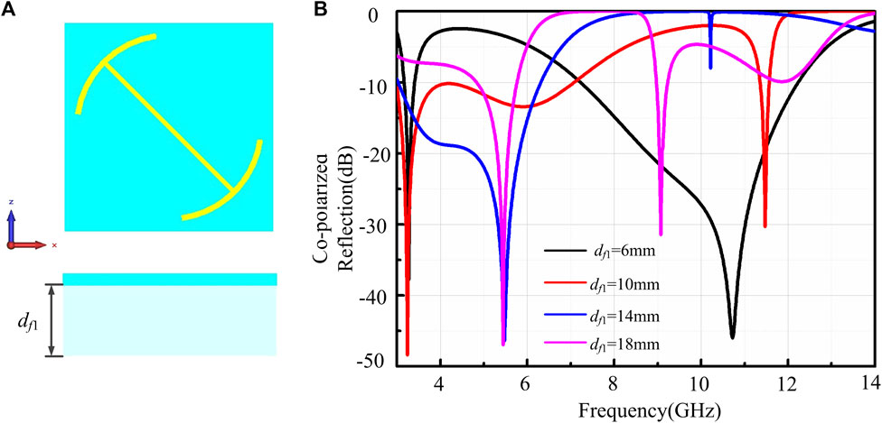
FIGURE 1. (A) Biarc meta-atom. (B) Co-polarized reflection varies with the foam thickness.
In general, the periodicity of a meta-atom determines its operating frequency band. However, as can be seen from Figure 1, when the periodicity is fixed, different substrate thicknesses will also change the working frequency band. Therefore, in addition to the element periodicity, element geometric pattern and parameters, dielectric constant of the substrate, and the thickness of several shifts are also one of the important factors affecting the metasurface performance. However, as a 2D array of sub-wavelength metallic patterns, the research on the metasurface has always focused on the design of the metal pattern structure and neglected the longitudinal thickness of the substrate. Therefore, the design freedom of the metasurface can be improved by engineering the thickness of the medium.
Inspired by the influence of substrate thickness on the operation frequency band, we can freely design the double PC band metasurface by manipulating the efficient thickness meeting the requirement of different operation bands. For such a design, the most critical step is to realize that the effective thickness varies with the frequency.
The most straightforward idea is to make the unit medium have double “catopter”, which low-frequency electromagnetic waves through the first catopter and reflected by the second, while high-frequency electromagnetic waves are directly reflected by the first reflective plate. The introduction of the antenna design has injected new life into the metasurface. The patch is a typical microstrip antenna and can radiate EMW. From another perspective, the circular patch can be regarded as an FSS structure which realizes the pass band in a low frequency while the stop band in a high frequency.
The functional schematic diagram is shown in Figure 2. The patch antenna radiator is inserted into the substrate of the biarc meta-atom and acts as a second high frequency catopter in addition to the metal back plate. Through such design, the thickness required of the PC is satisfied at both the low frequency and high frequency, and the PC dispersion of the meta-atom is customized. Outside the two PC bands, a co-polarized window is deliberately left as the radiation window. The EMWs radiated by the patch can pass directly through the element without changing the polarization state and radiation direction while ensuring the out-of-band scattering by utilizing the difference of the PB phase response to polarization. Through the above study, a bridge can be built in the design of the metasurface and antenna and makes the integrated design of radiation and scattering possible.
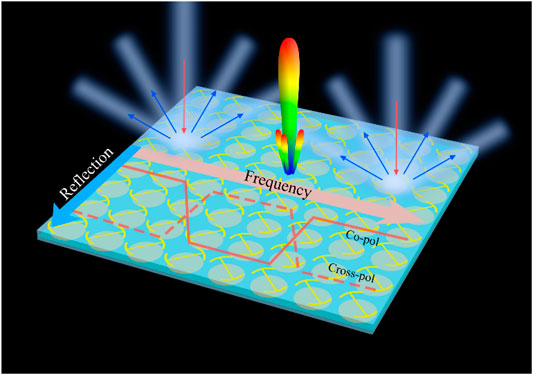
FIGURE 2. Diagram of the proposed design.
As a typical microstrip antenna, the circular patch has excellent radiation properties. Its structural schematic diagram is shown in Figure 3; the main composition includes the following: the circular patch, dielectric substrate (F4B, εr = 2.65, the loss tangent of 0.001), metal, and coaxial port. The geometric parameters of the antenna include the following: the period of the antenna element (18 mm, 0.4λ, where the is the wavelength at 7.3 GHz), the thickness of the substrate (2.7 mm), and the radius of the patch (7 mm). The S11 and radiation patterns of the patch antenna are given in Figures 3B,C by simulation. The main characteristic is that the radiation beam angle is larger, but the gain is lower. When a large gain is needed on a particular occasion, a plurality of antennas are usually required to form an antenna array to meet the requirement. Thus, the proposed antennas are arrayed to form an 8 × 8 array with the size of 144 × 144 mm. Inspired by the Wilkinson power splitter, a sixty-four port microstrip feeding network (MFN) is employed to excite the antenna array. The S11 and radiation diagrams after the array are shown in Figures 2E,F, and the gain increased to 19.7 dB at 7.3 GHz.
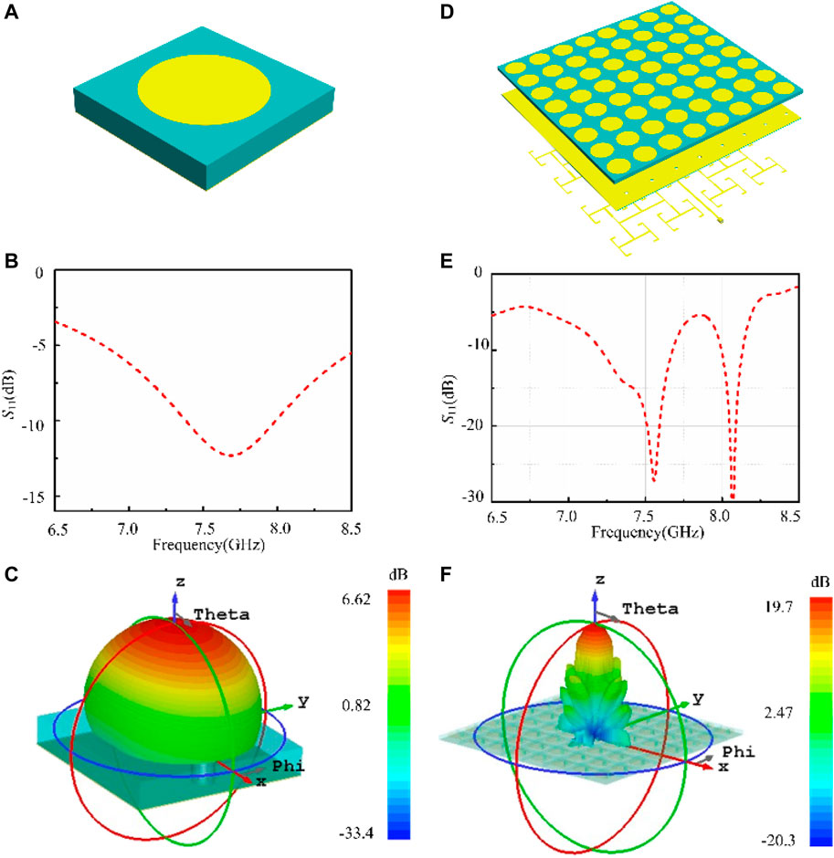
FIGURE 3. (A) Configuration of the antenna. (B) S11 of the antenna. (C) 3-D radiation patterns of the circular patch at 7.3 GHz. (D) Configuration of the antenna array. (E) S11 of the antenna array. (F) 3-D radiation patterns of the antenna array at 7.3 GHz.
The circular patch is not only a radiator but also an FSS with frequency selection characteristics (low frequency transmission and high frequency reflection). The traditional polarized conversion metasurface also has three layers, namely, the polarized rotating structure, dielectric substrate, and metal reflector plate, and the structure form is basically the same as the radiator. According to the theoretical analysis in Section 2, the performance of the polarized conversion surface is not only related to the structure pattern and period but is also closely related to the thickness of the dielectric substrate. Based on this, we can insert the circular patch into the dielectric substrate. The patch has band resistance characteristics, showing band pass characteristics at low frequencies and band resistance characteristics at high frequencies. Therefore, by inserting the patch into the substrate, it can simultaneously satisfy the condition that the thickness is small at high frequency and large at low frequency.
The electrical substrate thickness of the PC surface at different frequencies is adjusted via the band stop characteristic of the circular patch to meet the optimal thickness at different frequencies.
The combined structure is designed and shown in Figure 4. Figures 4A,B are the top and perspective view of the unit. The circular patch structure, a typical FSS structure, is inserted into the biarc unit. The metal patterns are etched on the F4B (εr = 2.65, the loss tangent of 0.001). The patterned slabs are pasted on polymethacrylimide (PMI) foams with εr = 1.1. Other geometrical parameters are as follows: a = 18.0 mm, w1 = 0.6 mm, w2 = 0.5 mm, d1 = 1.5 mm, d2 = 6 mm, d3 = 2.7 mm, α = 66, and r = 7 mm. The reflection (ryx, rxx, rxy and ryy) is shown in Figure 4C, in which ryx (rxx) represents the cross- (co-) polarization reflectivity under the x polarized wave while rxy (ryy) is the cross- (co-) polarization reflectivity under y polarized waves. Encouragingly, we can see the design can realize high PCR in two bands. One band is 2.9–6.1 GHz, and the other is 8.2–13.7 GHz. The co-polarized reflection is even lower than −10 dB. Besides, between the two cross-polarization reflection frequency bands, there is a co-polarization reflection window. In the co-polarization band, the cross-polarization reflection is even lower than −10 dB, too.
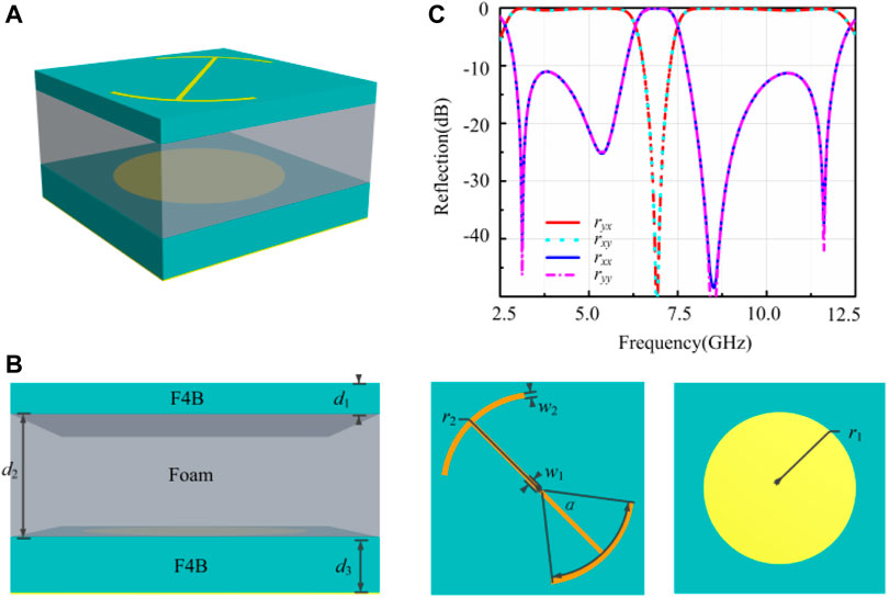
FIGURE 4. (A) Perspective view of the meta-atom. (B) Diagram of the meta-atom. (C) Co- and cross-polarized reflection of the meta-atom.
The polarization characteristics required by the theory are realized by inserting the antenna. In 2014, the researchers developed the PB phase concept and studied its relationship to the angle of rotation meta-atom. It is found that the phase of PB is only related to the orientation of the element and is independent of the frequency, that is, when the element is rotated by a, the phase changes by 2a. In addition, the PB phase only affects cross-polarized waves. According to the characteristics that the PB phase only responds to the cross-polarized wave, the phase profile of the out-of-band wave can be designed by rotating the biarc unit. Based on such an idea, the biarc structure was rotated 90 around the center. The cross-polarization reflection amplitude and the phase before and after the rotation are simulated and displayed in Figure 5A. Through rotation, the reflection phase required for the checkerboard arrangement is obtained while the amplitude is kept unchanged.
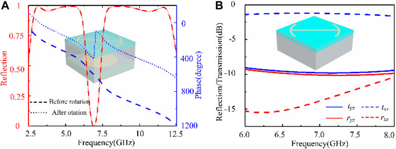
FIGURE 5. (A) Reflection amplitude and phase change before and after rotation (The different lines represent the rotation before and after). (B) Reflection and transmission of the PC surface under the x-polarized wave.
However, there is another issue need to be confirmed, that is, whether the radiation performance would be affected while increasing and arranging the PC surface into a chessboard structure. In this regard, the transmission and the reflection of the PC surface and the dielectric sheet are also simulated and depicted in Figure 5B. It is attested that the co-polarized transmission mainly occurs when the wave through the PC surface without the metal board and the phase of the co-polarized transmission wave will not change. Thus, it will not worsen the antenna array radiation performance.
The previous section demonstrated that the desired polarization characteristic can be obtained by inserting the antenna radiator into the substrate and forming a new meta-atom. The metasurface can be seen as an antenna aperture with low scatter and a great radiation performance.
First, we consider arranging the PC surface to manipulate the scattering wave. One of the most significant research methods to reduce the RCS is to propose the checkerboard structure. Its operation mechanism is based on the cancellation effect of both contributions. The RCS reduction can be approximately calculated by the following equation (Pang et al., 2018):
where A0 and A1 are the amplitudes of the different areas of the checkerboard, is the phase difference of the different area; f is the area fraction of the area 0. In other words, if the two meta-atoms have the same amplitude and the 180 ± 37 phase difference, the total scattering field will be cancelled in the normal direction and redirected toward the four principal quadrants.
In this case, the RCS and the far-field scattering pattern of the metasurface after arranging the chessboard are simulated and shown in Figure 6. Compared to the same size metal sheet, the bandwidth of RCS reduction covers 2.5–5.5 GHz and 8–12 GHz corresponding to a fractional bandwidth of 75 and 40%, respectively. From the far-field scattering pattern shown in the illustration, it is clearly seen that the EMW is scattered away from the normal incident direction.
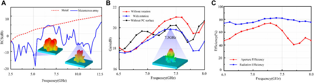
FIGURE 6. (A) Simulated RCS under the x-polarized wave and the illustrations are 3-D far-field scattering pattern at 5.0 and 10.0 GHz. (B) Simulated peak gain with and without rotating the PC unit. The illustration is radiation pattern at 7.3 GHz. (C) Radiation efficiency and aperture efficiency of the metasurface.
Then, we consider the radiation performance comparison, it is shown in Figures 6B,C. When inserting the antenna array into the PC surface substrate, we can see that the radiation gain is improved. This is mainly due to the cavity formed between the upper PC surface and the antenna surface. As can be seen in Figure 6B, when an electromagnetic wave passes through a PC surface, some is reflected rather than completely passed through the PC surface. This energy is reflected again by the antenna and re-reaches the polarized rotating surface. After multiple reflectance and transmission superposition, the gain is improved.
Compared with the metasurface of non-rotation, the gain loss is lower than 1 dB. The reason causing the gain loss is that the upper PC surface will inevitably produce a transmitted PC, even though the energy is small. This causes a small part of the radiated EMW to be scattered as cross-polarized waves when it passes through the PC surface, and the 3-D far-field scattering pattern depicted in Figure 6B also demonstrates it. Nevertheless, overall, the simulation result indicates that the proposed metasurface can realize the out-of-band RCS reduction while radiating the EMW. The radiation efficiency is simulated and shown in Figure 6C. The in-band high efficiency is realized, although the efficiency has a little loss. While for the out-of-band, the efficiency decreases rapidly because of the impedance mismatch. Additionally, the corresponding aperture efficiency of the proposed metasurface from 6.5 to 8.5 GHz is also given in Figure 5C, which is calculated by (Zhang et al., 2020):
where G and A denote the simulated gain and the physical area of the reflect array aperture. It is seen that the aperture efficiency has a maximum value of 74.1% at 7.3°GHz, which indicates a good radiation performance.
To verify the designed metasurface’s radiation property, its radiation patterns are simulated and shown in Figure 7. At the central frequency 7.3°GHz, the gain is 20.3°dB, the 3 dB angular width is 14° degrees, and the side lobe is −12.4 dB. By comparing the cross-polarized and co-polarized components, the cross-polarized level is lower than -10dB, which demonstrated that the metasurface’s radiation still has good polarization purity despite the existence of the PC metasurface in the upper layer.
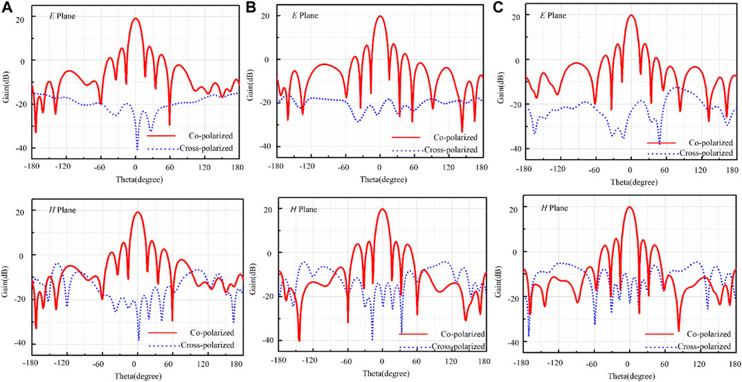
FIGURE 7. Simulated radiation pattern of the metasurface. (A) 7.1 GHz, (B) 7.3 GHz, and (C) 7.5 GHz.
In order to further confirm the design method and the metasurface performance, we fabricated a prototype with an area of 144 × 144 mm, and the structure of each layer is shown in Figure 8A. From the bottom to top are the following: the feed network, patch structure, foam, and polarized conversion structure. The radiation performances and the mono-static RCS of the metasurface are measured. Specifically, the S11 and the far-field radiation patterns of E and H plane are depicted in Figure 8C, respectively. For clarity, the simulation results are also given. It is observed that both the measured and simulated results agree well except that the measured S11 expands 250 MHz to low frequency. The main cause of frequency deviation is machining error, including coaxial port welding and microstrip line width, etc. Consistent with the simulation, the designed antenna can radiate efficiently within the 7.1–7.5 frequency band, and Figure 8C gives the measured far-field radiation patterns of E and H plane at f = 7.3 GHz (center frequency). The measured gain of the antenna array can achieve 19.6dB, which is a little bit lower than simulated (20.3°dB). The main reason why the measured result is lower than the simulated is that there are certain errors of the feed network and coaxial port compared with the simulation model. In addition, the air gap will increase the thickness when the upper metasurface is composited with the antenna array, which also affects the test result to a certain extent. However, the radiation performance of the measured gain is basically consistent with that of the simulation, which further verifies the feasibility of the design method.
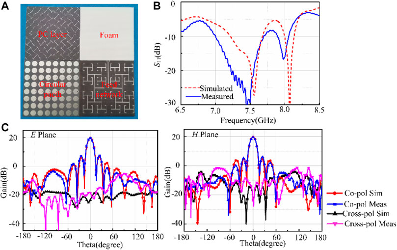
FIGURE 8. (A) Prototype photographs. (B) Simulated and measured S11. (C) Simulated and measured radiation pattern at 7.3 GHz.
Figure 9 depicts the measured mono-static RCS versus incident angle θi (−20∼20) at f = 5.0 and 10.0°GHz, respectively. And, the measured RCS of the metallic plate with the same area as the antenna array ground is also presented. By comparing with the metal plate, it can be found that the antenna array reduces RCS effectively in the normal direction, which is basically consistent with the simulation.
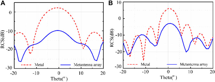
FIGURE 9. Measured mono-static RCS. (A) 5.0GHz (B) 10.0 GHz.
In summary, we proposed and verified the method of the metasurface design via incorporating antenna radiators into the substrates, which further brought new vitality to function integration and performance improvement. By inserting the antenna array into the dielectric substrate under the PC metasurface, the optimal electrical substrate thickness for PC at two separate bands is achieved simultaneously. Based on such a method, not only radiation function is added to the metasurfaces but also the original scattering-manipulation function is augmented. As a scatter, it can achieve efficient PC and then reduce out-of-band RCS. As a radiator, the patch array can efficiently radiate electromagnetic waves between the two RCS reduction bands. To verify the method and the design, we design and fabricate the metasurface prototype. Both the simulated and measured results demonstrate that the designed metasurface not only has satisfactory radiation performance but also realize the efficient RCS reduction. This work provides an alternative method of designing multi-functional metasurfaces, which may find applications in smart skins, 5/6G communications systems, and others.
The original contributions presented in the study are included in the article/supplementary material; further inquiries can be directed to the corresponding authors.
XF and YF contribute equally to this work including design, research, and simulation experiments. YH and JW contributed by coming up with design ideas and theoretical research. ZW carried out sample processing and experimental testing. MY and SQ polished and revised the manuscript.
This work was supported by the National Natural Science Foundation of China (NSFC) (Grant No. 61971435).
The authors declare that the research was conducted in the absence of any commercial or financial relationships that could be construed as a potential conflict of interest.
All claims expressed in this article are solely those of the authors and do not necessarily represent those of their affiliated organizations, or those of the publisher, the editors, and the reviewers. Any product that may be evaluated in this article, or claim that may be made by its manufacturer, is not guaranteed or endorsed by the publisher.
Chen, K., Feng, Y., Yang, Z., Cui, L., Zhao, J., Zhu, B., et al. (2016). Geometric Phase Coded Metasurface: from Polarization Dependent Directive Electromagnetic Wave Scattering to Diffusion-like Scattering. Sci. Rep. 6, 35968. doi:10.1038/srep35968
Cheng, Q., and Cui, T. J. (2006). Negative refractions in uniaxially anisotropic chiral media. Phys. Rev. B 73(11), 113104. doi:10.1103/PhysRevB.73.113104
Diaz-Rubio, A., Asadchy, V. S., Elsakka, A., and Tretyakov, S. A. (2017). Sci. Adv. 3, e1602714. doi:10.1126/sciadv.1602714
Fan, Y., Wang, J., Li, Y., Pang, Y., Zheng, L., Xiang, J., et al. (2018). Ultra-thin and -broadband Microwave Magnetic Absorber Enhanced by Phase Gradient Metasurface Incorporation. J. Phys. D: Appl. Phys. 51, 215001. doi:10.1088/1361-6463/aab8cd
Fu, X., Han, Y., Fan, Y., Wang, J., Zheng, L., Xu, Z., et al. (2021). Fss-embedded at synch: a facile method of augmenting functions of metasurfaces. Optics Express 29(26), 43531–43543. doi:10.1364/OE.439179
Han, Y., Zhu, L., Chang, Y., and Li, B. (2018). Dual-Polarized Bandpass and Band-Notched Frequency-Selective Absorbers under Multimode Resonance. IEEE Trans. Antennas Propagat. 66, 7449–7454. doi:10.1109/tap.2018.2870274
Hao, J. M., Ren, Q. J., An, Z. H., Huang, X. Q., Chen, Z. H., and Zhou, L (2009). Optical metamaterial for polarization control. Phys. Rev. A. 80(2), 023807. doi:10.1103/PhysRevA.80.023807
Huang, H., and Shen, Z. (2019). Low-RCS Reflectarray with Phase Controllable Absorptive Frequency-Selective Reflector. IEEE Trans. Antennas Propagat. 67, 190–198. doi:10.1109/tap.2018.2876708
Huang, H., Shen, Z., and Omar, A. A. (2017). 3-D Absorptive Frequency Selective Reflector for Antenna Radar Cross Section Reduction. IEEE Trans. Antennas Propagat. 65, 5908–5917. doi:10.1109/tap.2017.2751670
Iriarte Galarregui, Juan. Carlos., Amagoia Tellechea Pereda, , Luis Martínez de Falcón, José., Ederra, Iñigo., Gonzalo, Ramón., and Member, Peter. de. Maagt. (2013). Broadband Radar Cross-Section Reduction Using AMC Technology. IEEE Trans. Antennas Propagation 61, 6136–6143. doi:10.1109/tap.2013.2282915
Jiang, H., Xue, Z., Li, W., Ren, W., and Cao, M. (2016). Low-RCS High-Gain Partially Reflecting Surface Antenna with Metamaterial Ground Plane. IEEE Trans. Antennas Propagat. 64, 4127–4132. doi:10.1109/tap.2016.2589964
Li, H., Wang, G., Liang, J., Gao, X., Hou, H., and Jia, X. (2017). Single-Layer Focusing Gradient Metasurface for Ultrathin Planar Lens Antenna Application. IEEE Trans. Antennas Propagat. 65, 1452–1457. doi:10.1109/tap.2016.2642832
Liu, Y., Jia, Y., Zhang, W., Wang, Y., Gong, S., and Liao, G. (2019). An Integrated Radiation and Scattering Performance Design Method of Low-RCS Patch Antenna Array with Different Antenna Elements. IEEE Trans. Antennas Propagat. 67, 6199–6204. doi:10.1109/tap.2019.2925194
Lv, Q., Tang, Y., Zhang, B., Yin, L., Jin, C., and Mittra, R. (2020). Dual-Band Diffusive Metasurface-Based Reflector with Low Out-Of-Band Backscattering. IEEE Access 8, 217196–217203. doi:10.1109/access.2020.3042600
Modi, A. Y., Balanis, C. A., Birtcher, C. R., and Shaman, H. N. (2017). Novel Design of Ultrabroadband Radar Cross Section Reduction Surfaces Using Artificial Magnetic Conductors. IEEE Trans. Antennas Propagat. 65, 5406–5417. doi:10.1109/tap.2017.2734069
Pang, Y., Li, Y., Wang, J., Yan, M., Chen, H., Sun, L., et al. (2018). Carbon Fiber Assisted Glass Fabric Composite Materials for Broadband Radar Cross Section Reduction. Composites Sci. Tech. 158, 19–25. doi:10.1016/j.compscitech.2018.02.001
Pendry, J. B. (2000). Negative Refraction Makes a Perfect Lens. Phys. Rev. Lett. 85, 3966–3969. doi:10.1103/physrevlett.85.3966
Sihvola, A. (2007), Metamaterials in electromagnetics. Metamaterials 1, 2-11. doi:10.1016/j.metmat.2007.02.003
Smith, D. R., Pendry, J. B., and Wiltshire, M. C. K. (2004). Metamaterials and Negative Refractive Index. Science 305, 788–792. doi:10.1126/science.1096796
Sun, S., Yang, K.-Y., Wang, C.-M., Juan, T.-K., Chen, W. T., Liao, C. Y., et al. (2012). High-Efficiency Broadband Anomalous Reflection by Gradient Meta-Surfaces. Nano Lett. 12, 6223–6229. doi:10.1021/nl3032668
Wang, J. F., Qu, S. B., Xu, X., Ma, H., Xia, S., Yang, Y. M., et al. (2010), Normal-incidence left-handed metamaterials based on symmetrically connected split-ring resonators. Phys. Rev. E 81, 036601. doi:10.1103/physreve.81.036601
Wang, J., Li, Y., Jiang, Z. H., Shi, T., Tang, M.-C., Zhou, Z., et al. (2020). Metantenna: When Metasurface Meets Antenna Again. IEEE Trans. Antennas Propagat. 68, 1332–1347. doi:10.1109/tap.2020.2969246
Xie, P., Wang, G. M., Li, H. P., Liang, J. G., and Gao, X. J. (2019). Circularly Polarized Fabry-Perot Antenna Employing a Receiver‐Transmitter Polarization Conversion Metasurface. IEEE Trans. Antennas Propagation 68(4), 3213–3218. doi:10.1109/TAP.2019.2950811
Xu, H.-X., Sun, S., Tang, S., Ma, S., He, Q., Wang, G.-M., et al. (2016). Dynamical Control on Helicity of Electromagnetic Waves by Tunable Metasurfaces. Sci. Rep. 6, 27503. doi:10.1038/srep27503
Xu, H.-X., Wang, G.-M., Qi, M. Q., Cui, T. J., and Cai, T. (2013). Compact Dual-Band Circular Polarizer Using Twisted Hilbert-shaped Chiral Metamaterial. Opt. Express 21 (3), 24912–24921. doi:10.1364/oe.21.024912
Yu, Nan. Fang., Genevet, Patrice., Kats, M. A., Aieta, F., Tetienne, J-P., Capasso, F., et al. (2011). Light Propagation with Phase Discontinuities: Generalized Laws of Reflection and Refraction. Science 334 (6054), 333–337. doi:10.1126/science.1210713
Zhang, B. C, Jin, C., H Lv, Q., H Chen, J., and Tang, Y. (2020). IEEE Trans. Antennas Propag. 69, 4212–4216.
Zhang, L., Mei, S., Huang, K., and Qiu, C.-W. (2016). Advances in Full Control of Electromagnetic Waves with Metasurfaces. Adv. Opt. Mater. 4, 818–833. doi:10.1002/adom.201500690
Keywords: functional metasurface, radiation, RCS reduction, substrate engineering, antenna
Citation: Fu X, Fan Y, Han Y, Wang J, Wang Z, Yan M and Qu S (2022) Radiation-Scattering–Integrated Design of Multi-Functional Metasurfaces Based on Antenna-Embedded Substrates. Front. Mater. 8:806597. doi: 10.3389/fmats.2021.806597
Received: 01 November 2021; Accepted: 10 December 2021;
Published: 12 January 2022.
Edited by:
Ke Chen, Nanjing University, ChinaCopyright © 2022 Fu, Fan, Han, Wang, Wang, Yan and Qu. This is an open-access article distributed under the terms of the Creative Commons Attribution License (CC BY). The use, distribution or reproduction in other forums is permitted, provided the original author(s) and the copyright owner(s) are credited and that the original publication in this journal is cited, in accordance with accepted academic practice. No use, distribution or reproduction is permitted which does not comply with these terms.
*Correspondence: Yajuan Han, bXNoeWpfbWFpbEAxMjYuY29t; Jiafu Wang, d2FuZ2ppYWZ1MTk4MUAxMjYuY29t
†These authors have contributed equally to this work
Disclaimer: All claims expressed in this article are solely those of the authors and do not necessarily represent those of their affiliated organizations, or those of the publisher, the editors and the reviewers. Any product that may be evaluated in this article or claim that may be made by its manufacturer is not guaranteed or endorsed by the publisher.
Research integrity at Frontiers
Learn more about the work of our research integrity team to safeguard the quality of each article we publish.