 Dingge Yang1
 Guolin Xie
94% of researchers rate our articles as excellent or good
Learn more about the work of our research integrity team to safeguard the quality of each article we publish.
Find out more
ORIGINAL RESEARCH article
Front. Mater., 03 January 2022
Sec. Metamaterials
Volume 8 - 2021 | https://doi.org/10.3389/fmats.2021.804302
This article is part of the Research TopicAcoustic and Mechanical Metamaterials for Various ApplicationsView all 13 articles
Aiming at the noise control of the HVDC converter station, a one-dimensional two-port metamaterial muffler based on the acoustic slow-wave effect is designed and manufactured. The metamaterial muffler achieves a broadband quasi-perfect absorption of noise from 600 to 900 Hz while ensuring a certain ventilation capacity. In addition, the internal equivalent sound velocity curve and the sound pressure and velocity field of the muffler are used to reveal the mechanism of its broadband quasi-perfect sound absorption. The performance of the muffler was verified by theoretical, numerical, and experimental models. The work in this paper is of guiding significance for solving the noise problem in HVDC converter stations.
In the power grid system, the high-voltage direct current (HVDC) converter station is a kind of important power conversion equipment. Its primary function is to convert high-voltage alternating current into direct current or vice versa. The HVDC converter station mainly includes transformers, reactors, thyristors, AC and DC side filters, and cooling equipment. With the improvement of people’s living standards, the noise problem in HVDC converter stations has attracted more and more attention. According to previous research, the main noise in HVDC converter station is in the low-medium frequency band which will cause serious harm to personnel exposed to this environment (Li et al., 2016; Zhu et al., 2017; Wang et al., 2020). The commonly used noise reduction methods are mainly through changing the structure of the main equipment, traditional sound barriers, and active noise reduction technologies. The muffler is also a widely used noise reduction tool. It can allow airflow to achieve the purpose of heat dissipation and prevent the continued propagation of noise, which can better solve the noise and heat dissipation problems of HVDC.
The sound absorption performance of traditional dissipative mufflers (like porous materials) is closely related to their thickness, and their ventilation efficiency is not high. While reactive mufflers (like expansion chambers) are often larger, although they have better ventilation efficiency (Morse and Ingard, 1968; Munjal, 1987; Yang and Sheng, 2017). In recent years, the emergence of acoustic metamaterials has made it possible to better solve the noise problem of HVDC. The structure of the metamaterial mufflers is simple and light. Moreover, they can achieve quasi-perfect sound absorption of low frequency and broadband under the sub-wavelength size compared with the traditional mufflers. Also, they have better ventilation efficiency. Huang et al. proposed a drum muffler with a membrane structure that uses a tensioned diaphragm to form sound reflection by coupling a flexible wall and sound waves (Huang, 2002). Wang et al. proposed a composite elastic plate muffler by combining sound-absorbing materials and elastic plates (Wang et al., 2007; Wang and Huang, 2007). Li et al. designed a broadband double-layer micro-perforated ventilation muffler, which can achieve a sound absorption coefficient of more than 0.5 in the mid-frequency range (850–1000 Hz) on the basis of 70% ventilation efficiency (Li et al., 2018). Kumar et al. proposed a sound-absorbing muffler with a perforated neck and cavity that can be ventilated, achieving a sound absorption coefficient of 0.96 (1,000 Hz) at 45% of the opening area (Kumar et al., 2020). Kumar and Lee designed a wide-band ventilated sound-absorbing muffler using six folded channels (Kumar and Lee, 2020). Cheng et al. proposed a Mie resonator formed by eight symmetrical coiled cavities to achieve “slow sound velocity” noise reduction. (Cheng et al., 2015). Raze et al. introduced the Fano resonance concept into acoustics and proposed a spiral ventilation muffler (Raze et al., 2019).
At present, in addition to traditional mufflers, membrane-type mufflers and metamaterial mufflers are more researched. However, membrane-type mufflers face problems in terms of installation and durability. In contrast, metamaterial mufflers mostly rely on sound absorption and sound reflection to achieve narrow-band perfect absorption or broadband low-absorption coefficient goals. Furthermore, most mufflers have not studied the balance between acoustic and ventilation performance, making these structures unusable in some scenes requiring ventilation and heat dissipation. Therefore, a muffler with a wide frequency band, high absorption coefficient, and good ventilation efficiency is urgently needed to solve the noise problem of HVDC.
In this work, aiming at the noise problem of HVDC, we design a metamaterial muffler based on the acoustic slow-wave effect. The muffler is composed of multiple arrays of Fabry–Pérot (F–P) resonators, which can achieve broadband quasi-perfect absorption of sound waves in the middle and low-frequency bands and ensure a certain ventilation capacity. At the same time, compared with the traditional two-side open mufflers, the metamaterial muffler breaks the limitation of the sound absorption coefficient of less than 0.5. It can better solve the noise problem and heat dissipation problem of HVDC.
The remainder of this paper is structured as follows: Section 2 describes the metamaterial muffler design and the theory; Section 3 and Section 4 respectively verify the sound absorption performance of the muffler and analyze the mechanism of noise reduction; the study is concluded with final remarks in Section 5.
Most of the existing mufflers can be used for theoretical analysis of their acoustic response with a one-dimensional two-port acoustic waveguide model (Merkel et al., 2015). This type of system mainly relies on the acoustic wave loss structure placed on the edge of the air duct to dissipate the energy of the grazing sound wave. This model can be simplified as a point-symmetric scattering structure, and the sound absorption coefficients are all less than 0.5. According to Merkel’s research, if we can adjust the size to make the transmission coefficient and reflection coefficient at the target frequency equal to 0.5, the sound absorption coefficient can be set to 1. Considering that many dimensions affect the transmission coefficient and reflection coefficient of the Helmholtz resonator, the adjustment is more complicated, so we chose the F-P resonator as the basic structure to design the metamaterial muffler. Because the sound absorption performance of the F-P resonator is only related to the side length of the cross-section, and the resonance frequency is only related to the length of the resonator, which is more convenient to control (Xie and Wang, 2021).
Figure 1 shows the external and internal specific structures of the designed metamaterial muffler. Figure 1A shows the external dimensions of the muffler. The length
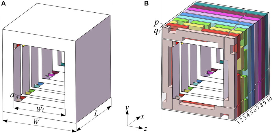
FIGURE 1. (A) The external schematic diagram of the metamaterial muffler; (B) The interior schematic diagram of the metamaterial muffler.
The size parameters of each unit are shown in Table 1.
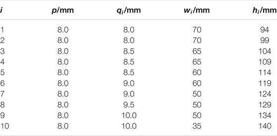
TABLE 1. Dimensions of each unit.
In order to derive the theoretical model of the muffler, we simplify Figure 1 as a 1/2 cross-sectional view of the x-y plane of the muffler in Figure 2. To facilitate the visual display of the height difference of the F-P tubes of each unit, we replace the coiled pipes with long straight tubes. It can be seen that the cross-sectional size and length of the four F-P tubes of the same unit are the same. The length
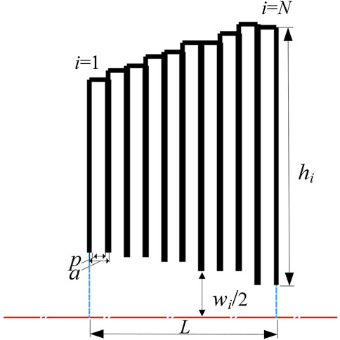
FIGURE 2. The 1/2 section view of the muffler x-y plane.
Next, we use the transfer matrix method to derive the theoretical model of the muffler. We define the sound pressure of the sound wave as
where
where
Due to the small cross-sectional area of the central through-hole and the F-P tube, we should consider the visco-thermal losses. So, we introduce the equivalent complex index. The medium is air with mass density
where
Next, we can get the transfer matrix of the central through hole of the
where
According to the existing thermal viscosity expression, the equivalent complex density
where
Similarly, the transfer matrix of the F-P tube of the
Because of the sudden area change between unit 10 and the pipe, we also need to consider the error caused by the sound wave radiating from the waveguide to the free space. The equivalent length correction term can be expressed as (Jimenez et al., 2017),
where
Due to the different cross-sectional area sizes of the central through holes between different units, there are discontinuities in the area. So it is also necessary to introduce a correction term to correct the radiation term of the sound wave. The radiation correction length from unit 1 to unit 9 can be expressed as:
Therefore, we can get the radiation correction impedance of each unit
After obtaining
where the free space air impedance
To analyze the acoustic performance of the proposed metamaterial muffler, a theoretical model, a numerical simulation model, and experiments were used for verification.
The theoretical model was established in MATLAB. The reflection coefficient and the sound energy transmission coefficient can be expressed by the system transfer matrix, and the sound absorption coefficient can then be expressed.
The numerical simulation model was established using the commercial finite element software COMSOL Multiphysics 5.4. The pressure acoustic module and the thermoacoustic module were adopted. The finite element simulation model consists of the upstream duct air domain, the metamaterial muffler air domain, and the downstream duct air domain. The pressure acoustic modules were used in the upstream duct air domain, downstream duct air domain, and the middle through-hole of the metamaterial muffler. The thermoacoustic module was used in the air domain of the coiled F-P tube. The boundaries of the air domain were considered as acoustic hard boundaries, and boundary-layer meshes with five layers were applied on the walls of the F-P tube. The incident sound wave was a plane wave with unit amplitude incident on the vertical metamaterial muffler. When the sound waves propagate to the muffler structure, part is reflected, part is absorbed and dissipated in the F-P tube, and part is transmitted from the muffler into the downstream duct. After expressing the reflection coefficient and transmission coefficient, the sound absorption coefficient of the muffler can be obtained. In addition, since the thermoacoustic simulation has more degrees of freedom and is limited by computer hardware conditions, the coiled F-P tube is equivalent to a long straight F-P tube.
In the experimental study, the metamaterial muffler was installed in a square impedance-tube system with a cross-sectional size is 100 mm × 100 mm. The upper limit frequency is 1700 Hz. We installed the muffler between the upstream and downstream standing wave tubes, and the end of the downstream standing wave tube was filled with a sponge. The sound absorption coefficient was measured by the standard transfer-function method. The experimental sample of the metamaterial muffler is shown in Figure 3. The material of the muffler is PLA resin, and its density, elastic modulus, and Poisson’s ratio are 1,160
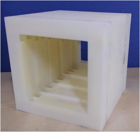
FIGURE 3. Experimental sample of the metamaterial muffler.
The sound absorption coefficient curves of the sample obtained by the theoretical, numerical, and experimental models are shown in Figure 4.
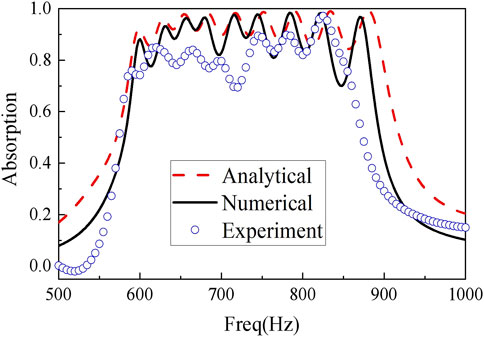
FIGURE 4. Comparison of theoretical, numerical, and experimental sound absorption coefficient curves of the sample.
The red dotted line in the figure is the result obtained from the theoretical model. The black solid line is the result obtained from the numerical simulation model. The last blue circle line is the result obtained from experimental measurements. The theoretical and simulation results show that the sound absorption coefficient is mostly maintained above 0.9 in the 600–900 Hz frequency band. Moreover, the sound absorption coefficient curve has nine sound absorption peaks. A valley value of the sound absorption coefficient appears between two adjacent sound absorption peaks. However, through a reasonable adjustment of the size between the muffler units, the valley value is also basically higher than 0.8. Combined with the experimental curves, the overall trend, amplitude, and position of the critical frequency of the three curves are basically the same, so it can be considered that the analytical solutions, simulation values, and experimental values are basically consistent. There is a certain difference between the experimental value of the sound absorption coefficient in the individual frequency bands (500–550 Hz, 700–750 Hz) and the simulated value, and the maximum error value does not exceed 0.2.
The experimental error is mainly because the accuracy of 3D printing is not high enough
After verifying the acoustic performance of the above metamaterial muffler, we can use this structure to reduce noise against the noise source of the HVDC converter station. Considering that the main transformer and high-voltage reactor are the main noise sources, we can use many designed metamaterial mufflers to form a wall to surround them to reduce noise. Of course, we can also apply it to other places where the noise is prominent.
In order to further analyze the mechanism of the muffler, first draw the internal equivalent sound velocity curve of the muffler, as shown in Figure 5. In the 500–950 Hz frequency band, the internal equivalent sound velocity of the muffler is much smaller than the free space sound velocity of 343
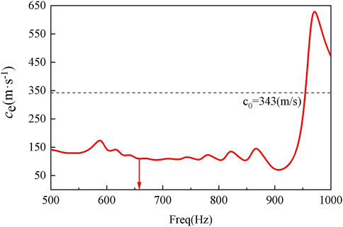
FIGURE 5. Internal equivalent sound velocity curve of the muffler.
In order to more intuitively explore the causes of slow waves, the pressure and velocity fields of the muffler are analyzed, and the results are shown in Figure 6. The figure shows the pressure velocity cloud diagram of the muffler when f = 656 Hz, that is, when unit 7 reaches resonance. It can be seen that since the sound waves of the inflow unit 7 and the outflow unit 8 are in anti-phase, the two interfere in the central through-hole and cancel each other. Most of the sound waves no longer propagate downstream, resulting in a reduction in the equivalent phase velocity of the sound waves. In the same way, at the resonance frequency of other units, the resonance unit, and adjacent units will also interfere with sound waves, resulting in a “slow-wave” phenomenon in a relatively wide frequency band.

FIGURE 6. The muffler pressure/velocity cloud graph at f = 656 Hz.
According to the currently designed structure, the unit with the smallest side length of the middle through-hole is unit 10, and its side length is 35 mm, so there is only 12.25% of the ventilation area. We sacrificed the ventilation area to obtain a wider sound absorption bandwidth and a higher sound absorption coefficient in the design. If we abandon unit 10 (sacrifice a peak at the low frequency), the minimum side length of the middle through-hole becomes 50 mm. The ventilation area becomes 25%. In addition, if the remaining space of the muffler is better utilized and the shape of the middle through-hole is optimized, the ventilation performance can be further improved. In this article, we only ensure a certain ventilation performance. The balance of acoustic performance and ventilation performance will be one of our main tasks in the future.
In short, we propose and manufacture a metamaterial muffler based on the slow-wave effect. Through ten specially designed units, the muffler breaks through the limitation that the sound absorption coefficient of the traditional two-side open muffler is less than 0.5. Moreover, we realize the broadband quasi-perfect absorption from 600 to 900 Hz while ensuring a certain ventilation capacity. We use finite element simulation and experiment to verify the noise reduction performance of the muffler, and the theoretical, simulation, and experimental results are in good agreement. In addition, through the internal sound pressure and velocity cloud diagram of the muffler, we found that the sound waves of the resonant unit and the adjacent unit are in opposite phases at the resonance frequency, causing the interference of the sound waves to cancel, achieving the purpose of noise elimination. At the same time, this also leads to a reduction in the equivalent phase velocity of the acoustic wave, resulting in a “slow-wave” phenomenon in a relatively wide frequency band.
The original contributions presented in the study are included in the article/Supplementary Material, further inquiries can be directed to the corresponding author.
DY and QJ have substantial contributions to the conception or design of the work; BD and YH worked for the acquisition, analysis or interpretation of data; BN and GX wrote the work and revised it critically for important intellectual content; JW was responsible for responding to reviewers' comments, follow-up work on paper production, and determining the final version to be published.
This work is supported by the State Grid Shaanxi Electric Power Company Technology Project (5226KY20001G).
DY, JW, YH, BD, and BN were employed by the State Grid Shaanxi Electric Power Research Institute.
The remaining authors declare that the research was conducted in the absence of any commercial or financial relationships that could be construed as a potential conflict of interest.
All claims expressed in this article are solely those of the authors and do not necessarily represent those of their affiliated organizations, or those of the publisher, the editors and the reviewers. Any product that may be evaluated in this article, or claim that may be made by its manufacturer, is not guaranteed or endorsed by the publisher.
Cheng, Y., Zhou, C., Yuan, B. G., Wu, D. J., Wei, Q., and Liu, X. J. (2015). Ultra-Sparse Metasurface for High Reflection of Low-Frequency Sound Based on Artificial Mie Resonances. Nat. Mater 14 (10), 1013–1019. doi:10.1038/Nmat4393
Huang, L. (2002). Modal Analysis of a Drumlike Silencer. J. Acoust. Soc. Am. 112 (5 Pt 1), 2014–2025. doi:10.1121/1.1508778
Jimenez, N., Romero-Garcia, V., Pagneux, V., and Groby, J. P. (2017). Quasi-Perfect Absorption by Subwavelength Acoustic Panels in Transmission Using Accumulation of Resonances Due to Slow Sound. Phys. Rev. B 95 (1), 014205. doi:10.1103/physrevb.95.014205
Kumar, S., and Lee, H. P. (2020). Labyrinthine Acoustic Metastructures Enabling Broadband Sound Absorption and Ventilation. Appl. Phys. Lett. 116 (13), 134103. doi:10.1063/5.0004520
Kumar, S., Xiang, T., and Lee, H. P. (2020). Ventilated Acoustic Metamaterial Window Panels for Simultaneous Noise Shielding and Air Circulation. Appl. Acoust. 159, 107088. doi:10.1016/j.apacoust.2019.107088
Li, J., Ji, S., Zhu, L., Wu, P., and Cao, T. (2016). Vibration Characteristics of Filter Capacitors Used in HVDC Converter Stations. IEEE Trans. Power Deliv. 31 (5), 2045–2053. doi:10.1109/TPWRD.2015.2483638
Li, L., Zheng, B., Zhong, L., Yang, J., Liang, B., and Jian, C. (2018). Broadband Compact Acoustic Absorber with High-Efficiency Ventilation Performance. Appl. Phys. Lett. 113 (10), 103501. doi:10.1063/1.5038184
Merkel, A., Theocharis, G., Richoux, O., Romero-Garcia, V., and Pagneux, V. (2015). Control of Acoustic Absorption in One-Dimensional Scattering by Resonant Scatterers. Appl. Phys. Lett. 107 (24), 244102. doi:10.1063/1.4938121
Munjal, M. L. (1987). Acoustic of Ducts and Mufflers with Application to Exhaust and Ventilation System Design. Hoboken, New Jersey: Wiley press.
Raze, G., Nikolajczyk, J., Anderson, S., and Zhang, X. (2019). Ultra-Open Acoustic Metamaterial Silencer Based on Fano-like Interference. Phys. Rev. B 99 (2), 024302. doi:10.1103/PhysRevB.99.024302
Wang, C., and Huang, L. (2007). Analysis of Absorption and Reflection Mechanisms in a Three-Dimensional Plate Silencer. J. Sound Vibration 313 (3), 510–524. doi:10.1016/j.jsv.2007.12.027
Wang, C., Han, J., and Huang, L. (2007). Optimization of a Clamped Plate Silencer. J. Acoust. Soc. Am. 121 (2), 949–960. doi:10.1121/1.2427126
Wang, L., Wu, J., Wei, J., Zhou, H., Geng, M., and Bai, X. (2020). “Study on Audible Noise Characteristics of Filter Capacitors and Reactors in HVDC Converter Stations by Using Sound Signal Processing Array Technique,” in 2020 5th Asia Conference on Power and Electrical Engineering (ACPEE), Chengdu, China, June, 2020, 1281–1285.
Xie, G., and Wang, X. (2021). Optimal Size Design of Fabry-Perot Sound Absorbers Based on the Loss Equation. J. Appl. Phys. 130 (1), 015111. doi:10.1063/5.0050502
Yang, M., and Sheng, P. (2017). Sound Absorption Structures: From Porous Media to Acoustic Metamaterials. Annu. Rev. Mater. Res. 47, 83–114. doi:10.1146/annurev-matsci-070616-124032
Keywords: metamaterial, muffler, acoustic slow-wave effect, high voltage direct current, noise control
Citation: Yang D, Jiang Q, Wu J, Han Y, Ding B, Niu B and Xie G (2022) Acoustic Slow-Wave Effect Metamaterial Muffler for Noise Control of HVDC Converter Station. Front. Mater. 8:804302. doi: 10.3389/fmats.2021.804302
Received: 29 October 2021; Accepted: 06 December 2021;
Published: 03 January 2022.
Edited by:
Han Jia, Institute of Acoustics (CAS), ChinaCopyright © 2022 Yang, Jiang, Wu, Han, Ding, Niu and Xie. This is an open-access article distributed under the terms of the Creative Commons Attribution License (CC BY). The use, distribution or reproduction in other forums is permitted, provided the original author(s) and the copyright owner(s) are credited and that the original publication in this journal is cited, in accordance with accepted academic practice. No use, distribution or reproduction is permitted which does not comply with these terms.
*Correspondence: Guolin Xie, Z3VvbGlueGllQGZveG1haWwuY29t
Disclaimer: All claims expressed in this article are solely those of the authors and do not necessarily represent those of their affiliated organizations, or those of the publisher, the editors and the reviewers. Any product that may be evaluated in this article or claim that may be made by its manufacturer is not guaranteed or endorsed by the publisher.
Research integrity at Frontiers
Learn more about the work of our research integrity team to safeguard the quality of each article we publish.