 Bence Kocsis
 Gábor Gulyás2,3
95% of researchers rate our articles as excellent or good
Learn more about the work of our research integrity team to safeguard the quality of each article we publish.
Find out more
ORIGINAL RESEARCH article
Front. Mater. , 18 January 2022
Sec. Thin Solid Films
Volume 8 - 2021 | https://doi.org/10.3389/fmats.2021.802076
In this research study, various additively fabricated coatings and bulk 3D-printed parts were prepared, using the mechanical and corrosion-resistant properties of CrMnFeCoNi (Cantor alloy) and AlCrMnFeNi high-entropy alloys (HEAs). The coatings were applied to an EN 1.0038 carbon steel substrate using direct metal laser sintering. We attempted to optimize the 3D printing parameters of HEA alloys. The effect of volumetric energy density (VED) on the microstructure was investigated by scanning electron microscopy. We also examined the change of relative concentration of alloys in the direction of 3D printing (z-axis) as well as the volumetric failures (cracks and gaps). Standard salt spray tests were performed to test the corrosion resistance of various coatings after 3D printing. The use of both raw materials applied as thick films was successful; they retained their corrosion-resistant properties even with a change in their composition. Regarding the crystal structure, no difference was found between the base material and the material applied as a coating on the basis of X-ray diffraction investigations. Bulk HEA printing experiments need further optimization concerning their structural integrity and density in the case of the Cantor alloy. Bulk 3D printing experiments of the AlCrMnFeNi alloy did not yield satisfactory results because of the formation of dendritic microstructure and brittle BCC phase, and the residual internal stress resulted in part distortion and improper printing.
Surface coatings improve some of the outstanding properties of the substrate. As a result, these parts are endowed with hybrid properties in mechanical, electric, magnetic, chemical, optical, or other fields (Li et al., 2019). The collective term used for this process is surface engineering. These properties can be formed by a special heat treatment, a chemical process, or adding a special material. Thin-film deposition typically works from several atomic layers to several micrometers, and thick-film techniques are applied from tens of microns to few millimeters (Murty et al., 2019). In this study, we prepared some thick films from two kinds of high-entropy alloys (HEAs) by powder bed fusion (PBF). Our goal was to develop HEA thick-film coating for structural applications in which we focus on the mechanical properties and corrosion resistance.
HEAs have attracted attention for over a decade (Gao and Lu, 2019). They represent a new class of alloy design; typically, a minimum of four elements are present in equal or nearly equal molar ratios. They form a simple yet chemically disordered solid solution even though they contain several components. Most of them compose face-centered cubic (fcc), body-centered cubic (bcc), or hexagonal close-packed (hcp) crystallographic structures (Huang et al., 2017). The higher cost of multicomponent HEAs may favor their applications primarily in coatings. According to Huang et al. (2004), the first coating by HEA was produced by thermal spray. The HEAs AlSiTiCrFeCoNiMo0.5 and AlSiTiCrFeNiMo0.5 preserved their FCC or FCC + BCC structure after deposition (Wang et al., 2009). At present, 3D printing (also called additive manufacturing, or AM) has been utilized. In particular, selective laser melting (SLM) has been widely used where the energy from the laser is used to melt a selected region of a layer and melting is repeated; thus, building the 3D component layer by layer (Hatos et al., 2020). The suitability of an HEA for AM is subject to the availability of micron-sized powder particles with a spherical morphology. Several elemental combinations have already been checked, such as CoxCrCuFeMnNi (Zhao et al., 2019), FeCoCrAlCuNix (Wu et al., 2017c), FeCoCrAlCu-X0.5 (Wu et al., 2017a), and FeCoCrAlNiTix (Wu et al., 2017b). They used laser surface alloying to coat CoCrFeMnNi and AlCoCrCuFeNix (x = 0.5, 1, and 1.5) HEA on steel and Cu substrates. Coated CoCrFeNi HEA exhibited noble corrosion resistance than the A36 steel substrate in 3.5wt% NaCl solution and 0.5 M sulfuric acid solution. The literature on the usage of AM methods for fabricating HEA coating is limited. Haase et al. successfully produced fully density, chemically homogeneous, bulk HEA parts from elemental powder blends by laser melting deposition. The chemical composition of the elemental powder blends and the printed part was exactly the same as the Cantor alloy (Haase et al., 2017). Ocalík et al. investigated the AlCoCrFeNi alloys by laser processing. They observed that the solidification rate has the greatest effect on the presence and distribution of phases (Ocelík et al., 2016). The reason for the increase in hardness is the rapid solidification, which increases the proportion of the BCC phase. Gao and Lu fabricated CoCrFeMnNi bulk HEA parts by the coaxial powder feeding laser 3D printing system (Gao and Lu, 2019). They observed an equiaxed-to-columnar transition structure in the melt pool. The microstructure shows a fine BCC phase which was distributed at the grain boundaries of the FCC matrix. Therefore, we aim to demonstrate the applicability of SLM in preparing coatings that confer superior properties to the workpiece. As to our knowledge, this is the first thick coating deposition by selective laser melting using CrMnFeCoNi (Cantor alloy) and its derivative AlCrMnFeNi.
During the experiments, two different raw materials were tested. The first was the classic Cantor alloy (Cr20Mn20Fe20Co20Ni20–HEA-1), which is a single-phase, face-centered cubic alloy. The other alloy was also a five-component, equiatomic HEA with the composition of AlCrMnFeNi (HEA-2). In addition to being cheaper than cobalt, the role of Al is to enhance the mechanical strength of the alloy through the formation of strong BCC (Masemola et al., 2020). The raw materials were produced by Sichuan Hermus Industry Co. Ltd. Two types of 3D printing experiments were performed. In the first case, we printed the powder on a base plate and created a thin coating. The base plate was made of the 1.0038 material, its size was 110 mm × 20 mm x 5 mm, and it was polished and degreased before the preparation. The powder was sintered into seven pieces of 5 mm × 18 mm, in each case, with a thickness of approximately 200 µm. The arrangement of the HEA-coated printing experiment is illustrated in Figure 1.
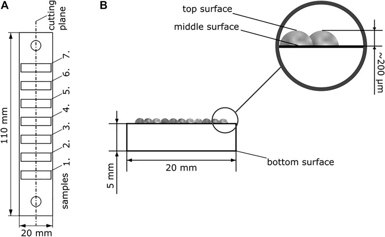
FIGURE 1. Top view (A) and front view (B) of the baseplate.
In the second printing experiment, we intended to investigate the printability of the materials in bulk form rather than the possibility of the thin-film behavior of HEA. For this purpose, we printed 25 pieces of 5 mm x 5 mm x 4 mm rectangular prisms with different parameter settings. To determine the laser sintering parameters, a simplified energy density calculation was used as follows:
where P—applied laser performance, v—laser scanning speed, h—hatch width, d—layer thickness (Ferro et al., 2020). The volume energy density (VED) applied to the steels (110–145 J/mm3) was kept porosity at a minimum based on our measurements. During printing experiments, this range of VED was targeted as the upper limit. Above this value, the material burns, and a poor-quality coating is formed. The print parameters used for the two print attempts are illustrated in Figure 2.
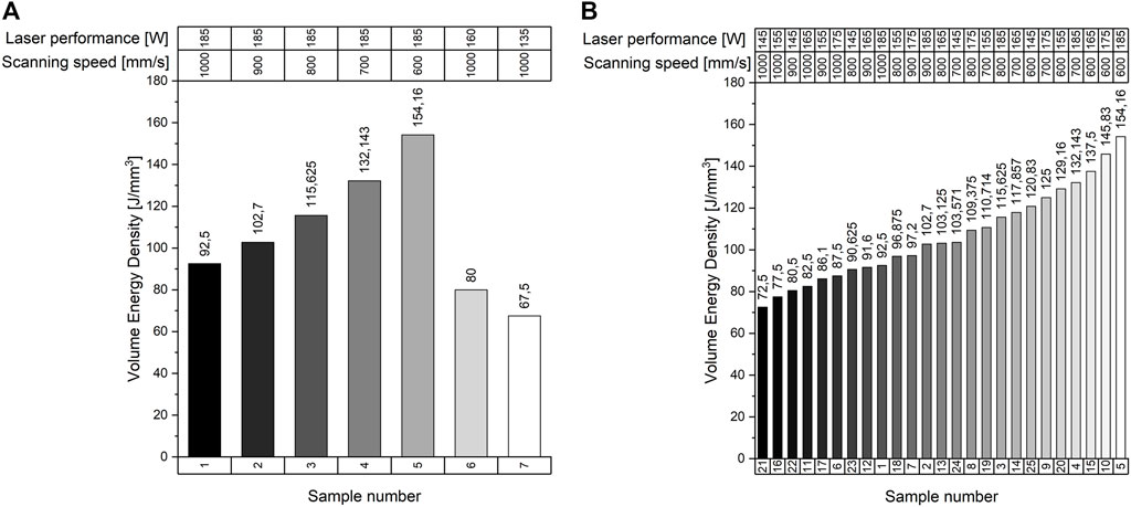
FIGURE 2. Printing parameters of the HEA coatings (A) and parameters of the rectangular prism (B).
Prior to the experimental procedure, raw material tests were performed on the two types of powder. The value of the lattice constant and the type of crystal structure were examined by X-ray diffraction. Measurements were performed with a Bruker (Germany) D8 diffractometer with Co anode (λ = 1.7890 Å), working at 40 kV and 40 mA. A stepping speed of 0.25°/min was applied for the 2Θ interval of 40–127°. Morphology investigation, particle size measurements, and chemical analyses were carried out applying a HITACHI 3400 scanning electron microscope (SEM) with a Bruker energy dispersive spectrometer (EDS). The chemical composition was also checked on the surface as well as on the cross sections of the particles. The powder was, then, fractionated using an 80 µm sieve. Also, 80µm ≥ powder particles were used for 3D printing experiments performed on an EOSINT M270 machine. This equipment utilizes powder bed fusion technology (PBF) and is capable of creating 3D parts by a direct metal laser sintering process. The machine is equipped with a Yb fiber laser with a nominal power of 200 W and a wavelength of 1070 nm. The working space was 250 mm × 250 mm × 215 mm, and the applied layer thickness was 20 µm in a nitrogen atmosphere. Samples were manufactured using a rotated scanning strategy that changed the scanning direction angle of each subsequent layer by 67°. All samples were made with a building platform temperature of 100°C.
After 3D printing, the base plate was cut into half, along its longitudinal axis. One of them was subjected to microscopic examination and the other one to corrosion investigation. SEM was used to analyze the interface between the carbon steel and HEA coating and to investigate the change of material composition after printing. Corrosion tests were carried out in an ASCOTT CC 1000ip cyclic corrosion chamber. The samples were kept in a 5% saline corrosive environment at 35°C for 48 h. The possibility of corrosion was photo-documented after 6, 24, and 48 h. After the corrosion tests, the sign of interfacial and surface corrosion was also examined visually and by scanning electron microscopy. In bulk HEA printing experiments, we investigated the behavior of the material at different volumetric energy density (VED) values. These samples were also carried out by SEM after grinding and polishing. During the microscopic examination, we studied the occurring microstructural cracks, porosities, and defects.
Figure 3 shows the X-ray diffraction patterns of the two HEAs, confirming the theoretical prediction of single-phase structures. The Cantor composition (A) in “as-received state” shows an FCC single-phase structure, with lattice constant a = 3.59147 Å and grain size D = 121 nm. The AlCrMnFeNi alloy had a BCC single phase with lattice constant a = 2.89472 Å and grain size D = 140 nm.

FIGURE 3. XRD patterns obtained on the (A) CrMnFeCoNi and (B) AlCrMnFeNi alloy, showing a single-phase FCC (A) and a single-phase BCC (B).
The SEM analyses revealed that the particle size ranged from a few microns to ∼100 microns. The morphology of most particles was spherical, according to the gas atomization manufacturing process; however, in some cases, we observed traces of droplets formation. HEA-2 powder sample shows a more uniform picture than HEA-1. Figure 4 shows the SEM images of the powder particles.
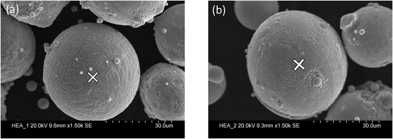
FIGURE 4. SEM images of the Cantor alloy powder (A) and AlCrMnFeNi powder raw material (B).
The surface and cross-sectional material composition were also investigated by SEM. Deviations from the theoretical five-component equiatomic HEA alloys were observed in both cases. For the Cantor alloy, the largest difference occurred on the surface in the case of manganese, which was exactly 2.07%. For the AlCrMnFeNi alloy, the maximum deviation at the surface was 1.24% for iron.
The exact measurement results are summarized in Figure 5. In light of the results, the Cantor alloy seemed to have the largest deviation of 1.84% for manganese, while AlCrMnFeNi had the largest difference in chromium (0.87%).
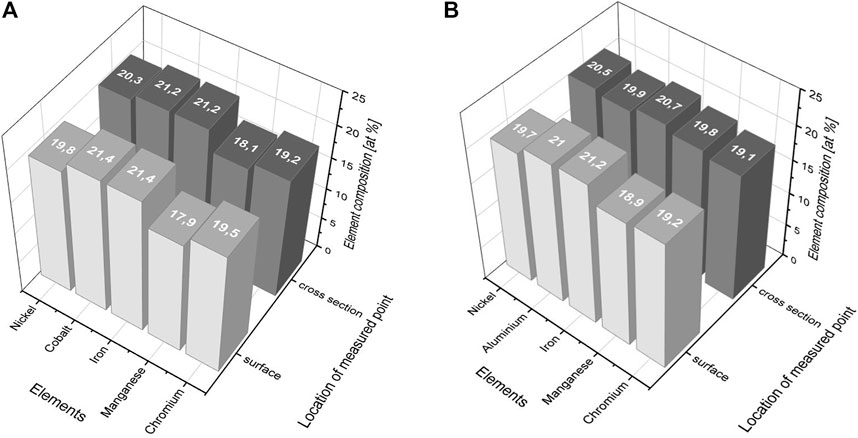
FIGURE 5. Results of material composition analyses for Cantor alloy (A) and AlCrMnFeNi (B).
After having printed the coatings, we noticed the following features: 1) the powder in a very thin layer behaved well during printing, 2) it could be spread out homogeneously, 3) the ablation rate was not significant, 4) there was no large amount of laser smog, and 5) the material did not crack during the process. The pieces were cut in a direction perpendicular to the printing plane and polished in the cutting plane. We examined the quality of adhesion along the section and looked for possible cracks and internal porosities.
Microscopic examinations confirmed that the interfacial bonds were adequate. There were no sharp transitions, and no porosities were observed along the coatings (see Figure 6 (a)). In Figure 6(a), the area between the red lines is shown the multiphase transition from the base plate (1.0038 carbon steel) and the deposited Cantor alloy. The same finding is valid for the other HEA alloy. Examining the change of the material composition along a section of 380 µm by EDX analysis, we found that the iron was enriched near the 3D-printed surface, and it presents in 38–40 at %. In the area between the blue and red lines, this value already exceeded 80%, and in the transition phase, it went up to 95%, which was close to the iron content of the base plate. Moving away from the coated surface, the highest amount of alloying element was cobalt, which was also present in the substrate material in a proportion of 2.5 at%. This was followed by nickel at 1.2 at% and followed by manganese and chromium at 0.5 at%. This was due to iron diffuses from the Fe-rich base plate into the coating layer through the technology-specific cyclic remelting. As cobalt has the highest diffusion coefficient among the HEA-1 elements when dissolved in iron, it makes sense for it to have a relatively high presence in the substrate. The blue line pattern draws the laser scan lines for the first few layers. The semicircular pattern was a trace of the formation and relatively rapid solidification of the melt pool. The yellow line is a straight line approaching the original surface of the carbon steel base plate. The element composition map shows that the element is equally distributed in the whole sample. Figure 6(c) and (d) illustrate the X-ray diffraction results after 3D printing. It can be clearly seen that the phase structure of the “as-received” and deposited HEAs is the same. In addition to the X-ray diffractograms of the HEAs, the BCC peaks of the base plate also appear. However, there was a change in grain size after printing. In the case of CrMnFeCoNi, the initial grain size of 121 nm became 50 nm, while for the AlCrMnFeNi, 140 nm became 44 nm.
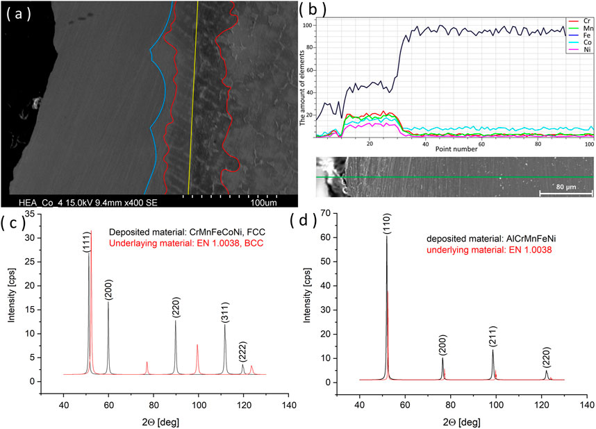
FIGURE 6. SEM image of the 3D-printed Cantor alloy on a carbon steel plate (sample #4) (A), an EDX line analysis of sample #3 after corrosion test (B) and XRD patterns of the deposited CrMnFeCoNi (C) and AlCrMnFeNi (D) coatings.
The change in the composition of coating during 3D printing was also detected by line analysis. As a result, its mechanical and chemical properties may also have changed. Compared to the raw material composition of the coatings, the proportion of manganese changed in the highest degree, presumably due to the evaporation during the cyclic remelting. Since the coatings were primarily made for corrosion resistance, the cut pieces were subjected to a corrosion test. Its advantage is that it allows for the study of the corrosion properties of the coating surface and the interface of the two materials. The carbon steel areas were masked with various adhesive tapes. The results of the tests are illustrated in Figure 7. The samples were also examined by visual inspection and microscopic examination. It can be concluded that no traces of corrosion were found visually on the coated parts. The rust flowed to the coated surface from the carbon steel base. The possible corrosion along the interfaces was also examined by SEM. In Figure 6B, the line analysis was already performed on a sample that had undergone a corrosion test. It shows that no corrosion process had emerged at the interface.
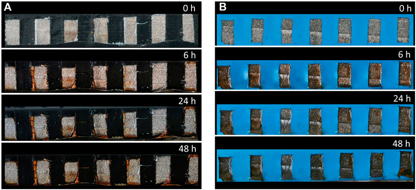
FIGURE 7. Photos of corrosion test samples after 0, 6, 24, and 48 h (A) represent the Cantor alloy coatings, while (B) represent AlCrMnFeNi.
In the following, we present the results of the bulk HEA printing experiments. The sintering experience was very different for the two materials. In the case of the Cantor alloy, the rectangular prisms were printed simultaneously with 25 different parameter settings. No difference was observed in printability for so large and simple geometries. The printed rectangular prisms are illustrated in Figure 8. It can also be seen in the enlarged images that flanging appears at the edges of the sample printed with a higher energy density (Figure 8C), which may be a long-term problem for larger and complex parts.
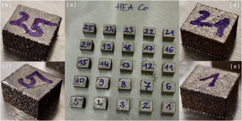
FIGURE 8. 3D-printed rectangular prisms (A). 145 [W]; 600 mm/s (B), 185 [W]; 600 mm/s (C), 145 [W]; 1,000 mm/s (D), 185 [W], 1,000 mm/s (E).
However, for the AlCrMnFeNi alloy, there was a significant difference in the quality of 3D-printed samples. During printing consisting of liner and contour scanning a concave cross section is formed with flanges which is detrimental to the multi layer deposition. Two of the samples printed with low laser power (145 W; 1,000 mm/s, 155 W; 1,000 mm/s) also broke during printing. The other samples also fell far from the quality of the printed Cantor alloy. In several cases, the sides of the prisms got detached due to the double effect of the contact with the recoater blade and the effect of high internal stress. In each case, the detachment started from the direction of the powder coating. This is because the presence of Al together with Ni results in hard interdendritic regions, which can cause such an error as a function of the stress state. Interestingly, samples made at a low scanning speed proved to be of the best quality, based on visual inspection. The image of the finished pieces is illustrated in Figure 9.
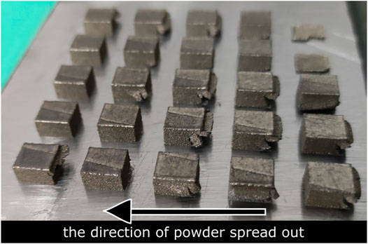
FIGURE 9. AlCrMnFeNi alloy after 3D printing.
Further investigations of bulk printing of the AlCrMnFeNi HEA alloy are not described. Additional iteration parameter settings need to be examined for proper printability and applicability.
Microscopic examination of the Cantor alloy revealed that the microstructure lags far from the ideal, quasi-porous free structure. In multiple instances, a microstructural defect could be observed at the boundary of the melt pool formation, which might later be the starting point for the formation of cracks. This was also observed when examining the top surface of sample number 1 (Figure 10); the structure almost opened at the boundary of the melt pool.
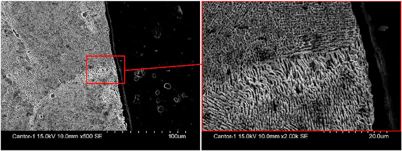
FIGURE 10. Melt pool interface defect on SEM images of the 3D-printed Cantor alloy (185 W; 1,000 mm/s).
At lower magnifications, the formation of these cracks is clearly visible in another sample (Figure 11). In terms of their orientation, the cracks typically extend in a Z direction of the print, i.e., in the direction of the layering. In the majority of cases, the crack started from such a melt pool interface defect in the + Z or – Z direction.
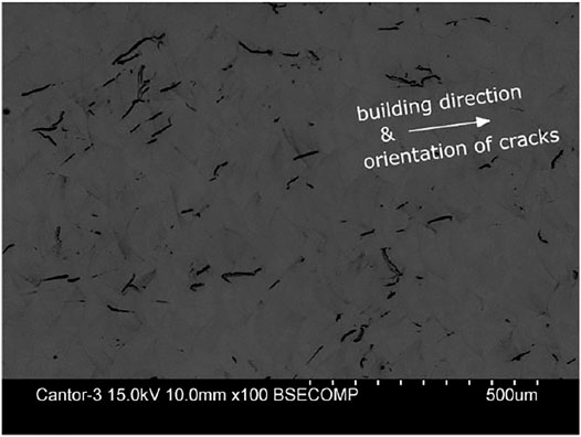
FIGURE 11. Cross-sectional SEM image of the 3D-printed #3 Cantor alloy sample.
The porosity of the samples was examined based on 10 characteristic values selected from the applied volume energy density spectrum. Based on microscopic images, a self-developed image analysis software evaluated the area-based percentage porosity of the given cross section. One important criterion for optimal 3D printing parameters was to keep porosity to a minimum. Figure 12 shows the results of the study described above.
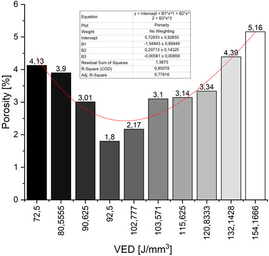
FIGURE 12. In the case of the Cantor alloy, the degree of porosity is a function of applied VED.
It can be clearly seen that the values sorted by energy density have a point resulting in a minimum porosity. This occurred at 92.5 J/mm3, which is sample number 1. It was made with 185 W and 1,000 mm/s parameters. In this particular case, porosity developed below 2%. However, it is important to note that the magnification and resolution of the inspected area of the image were limited to the amount of detected porosity.
Based on the results presented above, we can conclude that the two examined HEAs are suitable for preparing a thin, corrosion-resistant, ductile coating by PBF 3D printing technology. However, bulk HEA printing experiments have already led to more divisive results. Based on measurements and observations, the following findings can be made:
- Thin coating preparations are feasible by direct metal laser sintering technology in the case of CrMnFeCoNi and AlCrMnFeNi equiatomic HEAs.
- Due to the small Z-direction extension of the coating and the increased iron content from the base plate, there are no cracks in the material and no significant porosities; the interfacial adhesion connection is adequate.
- After deposition, no significant change in phase structure was observed, and only a particle size refinement was observed.
- Despite the enrichment of the iron content in the coating, both HEA alloys retain their corrosion resistance due to the alloy concentration being higher than 50 at%. There are no signs of surface or interfacial corrosion.
- Bulk 3D printing experiments of the AlCrMnFeNi alloy did not yield satisfactory results. Al-Ni-induced dendritic formation, brittle BCC phases, internal stresses during printing, and the appearance of flanging all resulted in part distortion and improper printing.
- In the case of the Cantor alloy, all VED values utilized led to successful printing; however, there were differences in the porosity and surface distortion of the samples. The best results were obtained in sample No. 1, which was produced with a laser power of 185 W and a scanning speed of 1,000 mm/s. Its porosity did not reach 2%.
Regarding further investigations, it is important to note that in the case of the AlCrMnFeNi material, additional experiments will be performed with parameter settings with lower energy density and low scanning speed. Computed tomography examinations will be executed to verify the real volumetric porosity. In the case of ablated powder particles, we have also examined the possible change of their composition, and we have found that the recycled powder does not behave as the new one. Concerning CrMnFeNiCo (Cantor alloy), we are planning to apply its cryogenic properties in coatings, and special devices are used in the refrigerant industry.
The original contributions presented in the study are included in the article, and further inquiries can be directed to the corresponding author.
GG performed the microscopic experiments; LKV contributed to the conception of the study; BK performed the 3D printing, X-ray diffraction experiments, and data analyses and contributed to the manuscript preparation.
The research was carried out as a part of the Ministry of Human Capacities through the project NTP-NFTÖ-21. The project was also supported by the Hungarian Scientific Research Fund (OTKA 128229).
The authors declare that the research was conducted in the absence of any commercial or financial relationships that could be construed as a potential conflict of interest.
All claims expressed in this article are solely those of the authors and do not necessarily represent those of their affiliated organizations, or those of the publisher, the editors, and the reviewers. Any product that may be evaluated in this article, or claim that may be made by its manufacturer, is not guaranteed or endorsed by the publisher.
Ferro, P., Meneghello, R., Savio, G., and Berto, F. (2020). A Modified Volumetric Energy Density-Based Approach for Porosity Assessment in Additive Manufacturing Process Design. Int. J. Adv. Manuf Technol. 110, 1911–1921. doi:10.1007/s00170-020-05949-9
Gao, X., and Lu, Y. (2019). Laser 3D Printing of CoCrFeMnNi High-Entropy alloy. Mater. Lett. 236, 77–80. doi:10.1016/j.matlet.2018.10.084
Haase, C., Tang, F., Wilms, M. B., Weisheit, A., and Hallstedt, B. (2017). Combining Thermodynamic Modeling and 3D Printing of Elemental Powder Blends for High-Throughput Investigation of High-Entropy Alloys - towards Rapid alloy Screening and Design. Mater. Sci. Eng. A 688, 180–189. doi:10.1016/j.msea.2017.01.099
Hatos, I., Fekete, I., Harangozó, D., and Hargitai, H. (2020). Influence of Local Porosity on the Mechanical Properties of Direct Metal Laser-Sintered 1.2709 Alloy. SV-JME 66, 351–357. doi:10.5545/sv-jme.2020.6573
Huang, P.-K., Yeh, J.-W., Shun, T.-T., and Chen, S.-K. (2004). Multi-Principal-Element Alloys with Improved Oxidation and Wear Resistance for Thermal Spray Coating. Adv. Eng. Mater. 6, 74–78. doi:10.1002/adem.200300507
Huang, S., Vida, Á., Heczel, A., Holmström, E., and Vitos, L. (2017). Thermal Expansion, Elastic and Magnetic Properties of FeCoNiCu-Based High-Entropy Alloys Using First-Principle Theory. JOM 69, 2107–2112. doi:10.1007/s11837-017-2565-6
Li, J., Huang, Y., Meng, X., and Xie, Y. (2019). A Review on High Entropy Alloys Coatings: Fabrication Processes and Property Assessment. Adv. Eng. Mater. 21, 1900343. doi:10.1002/adem.201900343
Masemola, K., Popoola, P., and Malatji, N. (2020). The Effect of Annealing Temperature on the Microstructure, Mechanical and Electrochemical Properties of Arc-Melted AlCrFeMnNi Equi-Atomic High Entropy alloy. J. Mater. Res. Technol. 9, 5241–5251. doi:10.1016/j.jmrt.2020.03.050
Murty, B. S., Yeh, J. W., Ranganathan, S., and Bhattacharjee, P. P. (2019). “High-entropy alloy Coatings,” in High-Entropy Alloys. Editors B. S. Murty, J. W. Yeh, S. Ranganathan, and P. P. Bhattacharjee. Second Edition (Elsevier), 177–193. doi:10.1016/B978-0-12-816067-1.00010-2
Ocelík, V., Janssen, N., Smith, S. N., and De Hosson, J. T. M. (2016). Additive Manufacturing of High-Entropy Alloys by Laser Processing. JOM 68, 1810–1818. doi:10.1007/s11837-016-1888-z
Wang, Y. P., Li, B. S., and Fu, H. Z. (2009). Solid Solution or Intermetallics in a High-Entropy Alloy. Adv. Eng. Mater. 11, 641–644. doi:10.1002/adem.200900057
Wu, C. L., Zhang, S., Zhang, C. H., Chen, J., and Dong, S. Y. (2017a). Phase Evolution Characteristics and Corrosion Behavior of FeCoCrAlCu-X 0.5 Coatings on Cp Cu by Laser High-Entropy Alloying. Opt. Laser Technol. 94, 68–71. doi:10.1016/j.optlastec.2017.03.023
Wu, C. L., Zhang, S., Zhang, C. H., Zhang, H., and Dong, S. Y. (2017b). Phase Evolution and Cavitation Erosion-Corrosion Behavior of FeCoCrAlNiTi X High Entropy alloy Coatings on 304 Stainless Steel by Laser Surface Alloying. J. Alloys Compd. 698, 761–770. doi:10.1016/j.jallcom.2016.12.196
Wu, C. L., Zhang, S., Zhang, C. H., Zhang, H., and Dong, S. Y. (2017c). Phase Evolution and Properties in Laser Surface Alloying of FeCoCrAlCuNi High-Entropy alloy on Copper Substrate. Surf. Coat. Technol. 315, 368–376. doi:10.1016/j.surfcoat.2017.02.068
Keywords: metal 3D printing, laser sintering, Cantor alloy, high-entropy alloy, additive technology
Citation: Kocsis B, Gulyás G and Varga LK (2022) Development of High-Entropy Alloy Coating by Additive Technology. Front. Mater. 8:802076. doi: 10.3389/fmats.2021.802076
Received: 26 October 2021; Accepted: 09 December 2021;
Published: 18 January 2022.
Edited by:
Tekalign Terfa Debela, Jeonju University, South KoreaReviewed by:
Ahmed Aliyu, Federal University, NigeriaCopyright © 2022 Kocsis, Gulyás and Varga. This is an open-access article distributed under the terms of the Creative Commons Attribution License (CC BY). The use, distribution or reproduction in other forums is permitted, provided the original author(s) and the copyright owner(s) are credited and that the original publication in this journal is cited, in accordance with accepted academic practice. No use, distribution or reproduction is permitted which does not comply with these terms.
*Correspondence: Bence Kocsis, a29jc2lzLmJlbmNlQGdhLnN6ZS5odQ==
Disclaimer: All claims expressed in this article are solely those of the authors and do not necessarily represent those of their affiliated organizations, or those of the publisher, the editors and the reviewers. Any product that may be evaluated in this article or claim that may be made by its manufacturer is not guaranteed or endorsed by the publisher.
Research integrity at Frontiers
Learn more about the work of our research integrity team to safeguard the quality of each article we publish.