 Hualiang Zhao1
 Boyi Li
 Xue Jiang
- 1Center for Biomedical Engineering, School of Information Science and Technology, Fudan University, Shanghai, China
- 2Academy for Engineering and Technology, Fudan University, Shanghai, China
We demonstrate the nondestructive evaluation by means of directional ultrasound emitted from a planar metasurface. The ultrasound metasurface is designed to generate the collimated and directional ultrasound efficiently in a planar configuration, which is endowed with the full-2π-range phase manipulation ability and high transmittance up to 80%. We employ the directional emission based on the ultrasound metasurface to innovate the traditional nondestructive evaluation methods, benefited from the freely controlled directivity and the superior fitness to sample surface of the planar metasurface. Merits of this innovative application are evidenced by the remarkable accuracy (higher than 98%) in the thickness evaluation, and precise detection (accuracy higher than 96%) of the special defect inside the V-shaped workpiece which is intractable to be inspected conventionally. The implementation of the metasurface-based directional ultrasound emission in the nondestructive evaluation bears the advantages of high coupling efficiency, superior fitness, high accuracy, and applicability to special defect, providing new solutions to the challenges in conventional defect detection and promotes the development in the nondestructive evaluation applications.
Introduction
Measurements based on acoustic waves have been widely explored in many applications such as nondestructive evaluation and biomedical engineering. In industrial nondestructive evaluation, the ultrasound measurements (Chatillon et al., 2000; Donskoy et al., 2001; Babich et al., 2004; Dutton et al., 2011a; Edwards et al., 2011; Edwards et al., 2012; Yassin et al., 2018; Taheri and Hassen, 2019) have been proved to be a powerful means for measuring and characterizing the workpieces. By analyzing the incident and reflected/transmitted ultrasound signals from the targeted workpiece, one can effectively characterize and obtain information about the workpiece, such as thickness (Hsu et al., 1994), density, speed of sound (Hans et al., 1996), and position of the defect inside the workpiece (Blackshire and Sathish, 2002; Yu et al., 2018). Ultrasound measurements have also been used in some fields like gas pipeline leakage detection (Liang et al., 2013) and food safety testing (Elvira et al., 2009). For the detection of targets in different scenarios, the collimated and directional ultrasound emission (Ren et al., 2010; Layman et al., 2011; Ren, 2015; Tang and Ren, 2017a; Tong et al., 2020) with varied incident angles is desired, which is conventionally realized by the combination of a planar transducer and the wedges of different angles (Bermes et al., 2008; Pruell et al., 2009). However, there are some limitations of these traditional methods for the directional ultrasound emission in the nondestructive detection (Dutton et al., 2011b). On the one hand, the employment of the wedge would introduce the impedance mismatch and influence the fitness to the sample surface, which would bring about the reduction in the transmission efficiency. On the other hand, for some special sample measurements such as the V-shaped workpiece, it might meet difficulties in placing the equipment for inspecting of the buried defect and thus affect the defection accuracy.
The emergence of acoustic metamaterial and metasurface (Chen and Chan, 2007; Chen and Chan, 2010; Zhao et al., 2013; Al Jahdali and Wu, 2016; Zhu et al., 2017; Chu et al., 2018; Zhao et al., 2019; Zhu and Assouar, 2019) could provide a new avenue to meet these challenges in nondestructive evaluation. One of the uniqueness of the metasurface lies in its ability to freely manipulate the wavefront by freely controlling the phase and amplitude of acoustic wave (Assouar et al., 2018). Benefiting from the special properties and sub-wavelength geometry of the metasurface, a variety of exotic acoustic phenomena, including acoustic cloaking (He et al., 2020), acoustic illusion (Shen et al., 2019a), super-resolution focusing (Li et al., 2015; Qian et al., 2017; Chen et al., 2018; Shen et al., 2019b), self-accelerating beams (Li and Assouar, 2015), acoustic vortex with twisted wavefront (Jiang et al., 2016; Ye et al., 2016), non-diffraction beams (Durnin et al., 1987), and asymmetric transmission (Li et al., 2017), have been successfully realized with acoustic metasurface. The efficient wave control ability of the metasurface also enables the directional and collimated emission in an ultrathin planar configuration, which could be employed to promote the applications in the traditional nondestructive evaluation and biomedical engineering. The directivity can be improved (Tang and Ren, 2017a; Tang and Ren, 2017b), and the emission direction can be controlled by adjusting the phase profile (Xia et al., 2017; Xia et al., 2018) on the metasurface based on the generalized Snell’s law (Yu et al., 2011).
In this work, we employ the acoustic metasurface as a powerful instrument to innovate the nondestructive evaluation, evidenced by the precise thickness evaluation and special defect inspection unavailable in the conventional methods. These are achieved by the collimated and directional ultrasound emission with the acoustic metasurface processing both the full-2π-range phase manipulation and the high transmittance (up to 80%). Based on the directional ultrasound emission, we numerically demonstrate the thickness evaluation and defect detection inside the special V-shaped workpiece, with remarkable accuracies higher than 98% and 96%, respectively. With the advantages of high coupling efficiency, superior fitness to sample surface, high accuracy, and applicability to special defect, the directional ultrasound emission based on the proposed planar metasurface would offer an alternative route to ultrasound measurements and boost the development in nondestructive evaluation.
Materials and methods
Multi-cavity element on the metasurface
We realize the directional ultrasound emission by designing the metasurface consisting of six identical cascaded elements. The schematic of an individual element is shown in Figure 1A, which is the combination of a rectangular cavity located in the center of the element and two symmetric inclined channels on both sides of the rectangular cavity. The structure is made of stainless steel, whose mass density, sound speed, Young’s modules, and Poisson’s ratio are

FIGURE 1. Acoustic metasurface for the collimated and directional ultrasound emission. (A) Schematic of an individual unit. (B) Phase delay and transmittance of an individual element, as functions of the parameter m. (C) Schematic of a metasurface unit consisting of six identical cascaded elements, with the periodicity of the element being
For achieving the full-2π-phase control, we connect six identical elements in series in the x-direction to construct a single unit, with the periodicity of the elements being
Design of the metasurfaces for directional ultrasound emission
The units consisting of six cascaded elements are arranged in the y-direction according to the generalized Snell’s law to design the ultrasound metasurface for directional emission. Considering the ultrasound wave normally incident from the x-direction, the transmitted ultrasound with the refraction angle
where
We numerically simulate the directional ultrasound emission based on COMSOL Multiphysics software. The distributions of the directional ultrasound fields with the refraction angles of 30° and 45° are illustrated in Figures 2A,B. The normally incident plane wave propagates along the x-direction and impinges on the metasurface, whose phase distribution is tuned by the metasurface. As a result, the transmitted ultrasound wave is endowed with the additional transverse momentum along the y-direction and passes through the metasurface with the targeted refraction angle. In Figures 2A,B, it can be observed that the incident ultrasound wave is deflected by 30° and 45° after passing through the metasurfaces, respectively, agreeing well with the targeted directions. In addition, the amplitude of the transmitted wave remains relatively high compared with the incident wave, which proves the high transmission of the metasurface and contributes to its application in nondestructive evaluation.
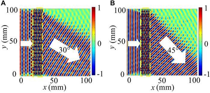
FIGURE 2. Directional ultrasound emission with the planar metasurface (indicated by the yellow dashed boxes) consisting of 80 units along the y-direction. The ultrasound at 300 kHz normally incident from the left are refracted by 30° in (A) and 45° in (B).
Results
The directional and collimated ultrasound emission based on the metasurface is employed in the thickness evaluation and defect detection inside the special V-shaped workpiece and provides an alternative route for nondestructive evaluation by taking advantage of the unique advantages of the high coupling efficiency, superior fitness, high accuracy, and applicability to special defect, which will be shown as follows.
Thickness evaluation
We first demonstrate the thickness evaluation of a plexiglass block underwater with the directional ultrasound emission of the refraction angle
Owing to the planar configuration, the designed metasurface can be directly attached to the surface of the detected workpiece which helps to reduce the mismatch caused by the wedge in conventional methods and improve the efficiency of the evaluation. A plane ultrasound at 300 kHz is normally incident from the left and transmits through the metasurface. As shown in the ultrasound intensity field in Figure 3A, ultrasound wave can almost completely penetrate the plexiglass block (indicated by the red solid box), and the transmitted beam is deflected to the direction of 45° by the metasurface (an enlarged view of it is shown in the green dashed box). The ultrasound beam transmitted from the metasurface is directionally emitted to the plexiglass block from the left surface and then further reflected by the right surface of the plexiglass block and detected on the left surface. The position of maximum ultrasound intensity on the left surface of the plexiglass block reveals the geometrical relationship between the emitted and reflected ultrasound trajectories and can be used to evaluate the thickness of the target.
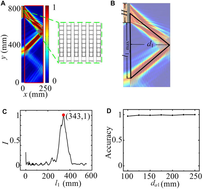
FIGURE 3. Thickness evaluation based on the collimated and directional ultrasound emission with the metasurface. (A) Spatial distribution of the ultrasound intensity in evaluating the thickness of the rectangular plexiglass block (indicated by the red solid box). The enlarged view of the planar metasurface is partially shown in the green dashed box. (B) Trajectories of the directional ultrasound beam emitted from the metasurface and reflected from the detected plexiglass block. (C) Ultrasound intensity distribution along the left surface of the plexiglass block, as a function of the distance l1 from the bottom of the metasurface. (D) The evaluation accuracy with the ultrasound metasurface for evaluating the plexiglass blocks of different thicknesses.
The trajectories of the directional ultrasound beam emitted from the metasurface and reflected from the right surface of the plexiglass block are illustrated in Figure 3B. The distance from the bottom of the metasurface on the left surface of the plexiglass block is denoted as l1. According to the geometric relationship (Figure 3B), the thickness of the block can be calculated by:
where l1_max is the position of the maximum ultrasound intensity.
An ultrasound intensity profile as a function of l1 is plotted in Figure 3C, which shows that the intensity reaches the maximum value at position
To compare the thickness evaluation performance based on ultrasound metasurface for the workpiece with different thicknesses, we conduct the evaluation of the plexiglass blocks with the thickness da1 ranging from 100 to 250 mm. The evaluation accuracy as a function of the thickness da1 is plotted in Figure 3D, where it is consistently higher than 98% over this thickness range. The consistency between the evaluated and actual thicknesses strongly proves the high accuracy and effectiveness of the implementation of the directional ultrasound emission based on metasurface in thickness evaluation, which provides broad interests on the applications in industrial engineering.
Defect detection inside the V-shaped workpiece
We further consider the defect detection inside the object with the metasurface-based directional emission. As an example, we demonstrate the testing of the defect inside a V-shaped workpiece, which is widely used in industry while quite challenging to detect for a conventional wedge-based method due to the special shape. Figure 4A shows the schematic of a V-shaped workpiece made of plexiglass with a strip of air defect inside it. We use the constructed metasurface which can emit the directional ultrasound beam to detect the strip defects inside the workpiece. Figure 4B shows the two-dimensional cross section of defect detection inside the V-shaped workpiece. The metasurface (indicated by the green dashed box) and the V-shaped workpiece (indicated by the red solid box) are immersed in water, and the planar metasurface is closely adherent to the surface of the workpiece. A plane ultrasound wave impinges on the upper surface of the metasurface and is transmitted through the metasurface with the refraction angle of 45°. The transmitted ultrasound beam is then emitted into the V-shaped workpiece and interacts with the defect inside, which leads to the reflection by the defect due to the acoustic impedance mismatch between the plexiglass and air stripe, and the reflected signal is detected on the top-right surface of the workpiece. Similarly, the position of the defect can be found by analyzing the trajectories of the emitted and reflected beams, and the geometric relationship of the V-shaped workpiece and the strip defect (Figure 4C).
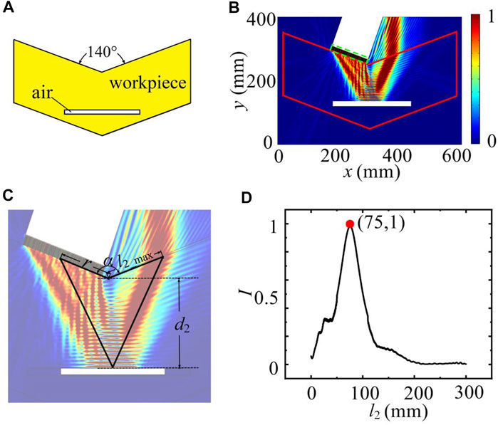
FIGURE 4. The defect detection inside the V-shaped workpiece with the planar ultrasound metasurface. (A) The schematic of the V-shaped workpiece made of plexiglass with a strip of air defect inside it. (B) Ultrasound intensity distribution in the defect detection inside the V-shaped workpiece (indicated by the red solid box) with the planer metasurface (green dashed box). (C) Trajectories of the directional emitted and reflected ultrasound beams. (D) Distributions of ultrasound intensity along the top-right surface of the workpiece, as function of the distance l2 from the corner of the workpiece.
Specifically, the position of the maximum ultrasound intensity on the top-right surface l2_max indicates the position of the defect inside the workpiece. The V-shaped workpiece tested here has the included angle of
which is calculated to be
Discussion
In conclusion, we have theoretically proposed and numerically demonstrated the nondestructive evaluation including the thickness evaluation and special defect detection by means of directional ultrasound waves emitted from a planar metasurface. The metasurface composed of parallel multi-cavity cascaded elements has been designed, which ensures a flexible 2π-range phase control while maintaining the transmittance up to 80%. The thickness evaluation with the accuracy higher than 98% has been achieved, and the comparison of the performance for evaluating different thicknesses has been discussed. Furthermore, the precise inspection of the defect located inside the V-shaped workpiece unavailable with conventional methods has been efficiently realized with the accuracy higher than 96%. The nondestructive evaluation with the metasurface-based directional ultrasound emission, with the merits of high coupling efficiency, superior fitness to sample surface, high accuracy, and applicability to special defect, would provide additional solutions to the challenges in conventional defect detection and promote the development in nondestructive evaluation applications.
Data Availability Statement
The raw data supporting the conclusion of this article will be made available by the authors, without undue reservation.
Author Contributions
HZ and XJ conceived the research. XJ and DT supervised the project. HZ performed the theoretical calculation and analysis. XJ, JH, and CZ contributed to perform the analysis with constructive discussions. All authors contributed to manuscript revision and read and approved the submitted version.
Funding
This work was supported by the National Natural Science Foundation of China (Grants Nos. 11904055, 12034005, and 11827808), the Science and Technology Innovation Plan of Shanghai Science and Technology Commission (Grant Nos. 20ZR1404200 and 21JC1400300), the Shanghai Chenguang Program (Grant No. 20CG02), and the Program of Shanghai Academic Research Leader (Grant No. 19XD1400500).
Conflict of Interest
The authors declare that the research was conducted in the absence of any commercial or financial relationships that could be construed as a potential conflict of interest.
Publisher’s Note
All claims expressed in this article are solely those of the authors and do not necessarily represent those of their affiliated organizations, or those of the publisher, the editors, and the reviewers. Any product that may be evaluated in this article, or claim that may be made by its manufacturer, is not guaranteed or endorsed by the publisher.
References
Al Jahdali, R., and Wu, Y. (2016). High Transmission Acoustic Focusing by Impedance-Matched Acoustic Meta-Surfaces. Appl. Phys. Lett. 108 (3), 031902. doi:10.1063/1.4939932
Assouar, B., Liang, B., Wu, Y., Li, Y., Cheng, J.-C., and Jing, Y. (2018). Acoustic Metasurfaces. Nat. Rev. Mater. 3 (12), 460–472. doi:10.1038/s41578-018-0061-4
Babich, V. M., Borovikov, V. A., Fradkin, L. J., Kamotski, V., and Samokish, B. A. (2004). Scatter of the Rayleigh Waves by Tilted Surface-Breaking Cracks. NDT E Int. 37 (2), 105–109. doi:10.1016/j.ndteint.2003.05.001
Bermes, C., Kim, J.-Y., Qu, J., and Jacobs, L. J. (2008). Nonlinear Lamb Waves for the Detection of Material Nonlinearity. Mech. Syst. Signal Process. 22 (3), 638–646. doi:10.1016/j.ymssp.2007.09.006
Blackshire, J. L., and Sathish, S. (2002). Near-field Ultrasonic Scattering from Surface-Breaking Cracks. Appl. Phys. Lett. 80 (18), 3442–3444. doi:10.1063/1.1476722
Chatillon, S., Cattiaux, G., Serre, M., and Roy, O. (2000). Ultrasonics 38 (1), 131–134. doi:10.1016/s0041-624x(99)00181-x
Chen, D.-C., Zhu, X.-F., Wei, Q., Wu, D.-J., and Liu, X.-J. (2018). Broadband Acoustic Focusing by Airy-like Beams Based on Acoustic Metasurfaces. J. Appl. Phys. 123 (4), 044503. doi:10.1063/1.5010705
Chen, H., and Chan, C. T. (2010). Acoustic Cloaking and Transformation Acoustics. J. Phys. D: Appl. Phys. 43 (11), 113001. doi:10.1088/0022-3727/43/11/113001
Chen, H., and Chan, C. T. (2007). Acoustic Cloaking in Three Dimensions Using Acoustic Metamaterials. Appl. Phys. Lett. 91 (18), 183518. doi:10.1063/1.2803315
Chu, H., Li, Q., Liu, B., Luo, J., Sun, S., Hang, Z. H., et al. (2018). A Hybrid Invisibility Cloak Based on Integration of Transparent Metasurfaces and Zero-index Materials. Light Sci. Appl. 7 (1), 50. doi:10.1038/s41377-018-0052-7
Donskoy, D., Sutin, A., and Ekimov, A. (2001). Nonlinear Acoustic Interaction on Contact Interfaces and its Use for Nondestructive Testing. NDT E Int. 34 (4), 231–238. doi:10.1016/s0963-8695(00)00063-3
Durnin, J., Miceli, J. J., and Eberly, J. H. (1987). Diffraction-free Beams. Phys. Rev. Lett. 58 (15), 1499–1501. doi:10.1103/physrevlett.58.1499
Dutton, B., Clough, A. R., and Edwards, R. S. (2011). Near Field Enhancements from Angled Surface Defects; A Comparison of Scanning Laser Source and Scanning Laser Detection Techniques. J. Nondestruct Eval. 30 (2), 64–70. doi:10.1007/s10921-011-0091-y
Dutton, B., Clough, A. R., Rosli, M. H., and Edwards, R. S. (2011). Non-contact Ultrasonic Detection of Angled Surface Defects. NDT E Int. 44 (4), 353–360. doi:10.1016/j.ndteint.2011.02.001
Edwards, R. S., Dutton, B., and Clough, A. R. (2012). Interaction of Laser Generated Ultrasonic Waves with Wedge-Shaped Samples. Appl. Phys. Lett. 100 (18), 184102. doi:10.1063/1.4711021
Edwards, R. S., Dutton, B., Clough, A. R., and Rosli, M. H. (2011). Enhancement of Ultrasonic Surface Waves at Wedge Tips and Angled Defects. Appl. Phys. Lett. 99 (9), 094104. doi:10.1063/1.3629772
Elvira, L., Rodríguez, J., and Lynnworth, L. C. (2009). Sound Speed and Density Characterization of Milk Adulterated with Melamine. J. Acoust. Soc. Am. 125 (5), EL177–EL182. doi:10.1121/1.3104625
Hans, D., Fuerst, T., and Uffmann, M. (1996). Curr. Opin. Rheumatol. 8 (4), 16. doi:10.1097/00002281-199607000-00016
He, J., Jiang, X., Ta, D., and Wang, W. (2020). Experimental Demonstration of Underwater Ultrasound Cloaking Based on Metagrating. Appl. Phys. Lett. 117 (9), 091901. doi:10.1063/5.0021002
Hsu, D. K., Ayres, A. M., Guangda, M., and Guangwen, M. (1994). Simultaneous Determination of Ultrasonic Velocity, Plate Thickness and Wedge Angle Using One-Sided Contact Measurements. NDT E Int. 27 (2), 75–82. doi:10.1016/0963-8695(94)90313-1
Jiang, X., Li, Y., Liang, B., Cheng, J.-c., and Zhang, L. (2016). Phys. Rev. Lett. 117 (3), 034301. doi:10.1103/physrevlett.117.034301
Layman, C. N., Martin, T. P., Moore, K. M., Calvo, D. C., and Orris, G. J. (2011). Designing Acoustic Transformation Devices Using Fluid Homogenization of an Elastic Substructure. Appl. Phys. Lett. 99 (16), 163503. doi:10.1063/1.3652914
Li, Y., and Assouar, M. B. (2015). Three-dimensional Collimated Self-Accelerating Beam through Acoustic Metascreen. Sci. Rep. 5 (1), 17612. doi:10.1038/srep17612
Li, Y., Jiang, X., Liang, B., Cheng, J.-c., and Zhang, L. (2015). Phys. Rev. Appl. 4 (2), 024003. doi:10.1103/physrevapplied.4.024003
Li, Y., Shen, C., Xie, Y., Li, J., Wang, W., Cummer, S. A., et al. (2017). Phys. Rev. Lett. 119 (3), 035501. doi:10.1103/physrevlett.119.035501
Liang, W., Zhang, L., Xu, Q., and Yan, C. (2013). Gas Pipeline Leakage Detection Based on Acoustic Technology. Eng. Fail. Anal. 31, 1–7. doi:10.1016/j.engfailanal.2012.10.020
Pruell, C., Kim, J.-Y., Qu, J., and Jacobs, L. J. (2009). A Nonlinear-Guided Wave Technique for Evaluating Plasticity-Driven Material Damage in a Metal Plate. NDT E Int. 42 (3), 199–203. doi:10.1016/j.ndteint.2008.09.009
Qian, J., Xia, J.-p., Sun, H.-x., Yuan, S.-q., Ge, Y., and Yu, X.-z. (2017). Broadband Acoustic Focusing by Cavity Structures with Phase Manipulations. J. Appl. Phys. 122 (24), 244501. doi:10.1063/1.4998223
Ren, C. (2015). Compact Acoustic Antenna Design Using Labyrinthine Metamaterials. Appl. Phys. A. 119 (2), 461–465. doi:10.1007/s00339-015-9057-8
Ren, C., Xiang, Z., and Cen, Z. (2010). Design of Acoustic Devices with Isotropic Material via Conformal Transformation. Appl. Phys. Lett. 97 (4), 044101. doi:10.1063/1.3467852
Shen, Y.-X., Peng, Y.-G., Cai, F., Huang, K., Zhao, D.-G., Qiu, C.-W., et al. (2019). Ultrasonic Super-oscillation Wave-Packets with an Acoustic Meta-Lens. Nat. Commun. 10 (1), 3411. doi:10.1038/s41467-019-11430-3
Shen, Y., Zhu, X., Cai, F., Ma, T., Li, F., Xia, X., et al. (2019). Phys. Rev. Appl. 11 (3), 034009. doi:10.1103/physrevapplied.11.034009
Tang, W., and Ren, C. (2017). Beam Aperture Modifier Design with Acoustic Metasurfaces. J. Phys. D: Appl. Phys. 50 (42), 425104. doi:10.1088/1361-6463/aa89dc
Tang, W., and Ren, C. (2017). Total Transmission of Airborne Sound by Impedance-Matched Ultra-thin Metasurfaces. J. Phys. D: Appl. Phys. 50 (10), 105102. doi:10.1088/1361-6463/aa5a86
Tong, S., Ren, C., Tao, J., and Tang, W. (2020). Anisotropic index-near-zero Metamaterials for Enhanced Directional Acoustic Emission. J. Phys. D: Appl. Phys. 53 (26), 265102. doi:10.1088/1361-6463/ab7df3
Xia, J.-p., Sun, H.-x., and Yuan, S.-q. (2017). Modulating Sound with Acoustic Metafiber Bundles. Sci. Rep. 7 (1), 8151. doi:10.1038/s41598-017-07232-6
Xia, J.-p., Zhang, X.-t., Sun, H.-x., Yuan, S.-q., Qian, J., and Ge, Y. (2018). Phys. Rev. Appl. 10 (1), 014016. doi:10.1103/physrevapplied.10.014016
Yassin, A., Rahman, M. S. U., and Abou-Khousa, M. A. (2018). Imaging of Near-Surface Defects Using Microwaves and Ultrasonic Phased Array Techniques. J. Nondestruct Eval. 37 (4), 71. doi:10.1007/s10921-018-0526-9
Ye, L., Qiu, C., Lu, J., Tang, K., Jia, H., Ke, M., et al. (2016). Making Sound Vortices by Metasurfaces. AIP Adv. 6 (8), 085007. doi:10.1063/1.4961062
Yu, N., Genevet, P., Kats, M. A., Aieta, F., Tetienne, J.-P., Capasso, F., et al. (2011). Light Propagation with Phase Discontinuities: Generalized Laws of Reflection and Refraction. Science 334 (6054), 333–337. doi:10.1126/science.1210713
Yu, Q., Obeidat, O., and Han, X. (2018). Ultrasound Wave Excitation in thermal NDE for Defect Detection. NDT E Int. 100, 153–165. doi:10.1016/j.ndteint.2018.09.009
Zhao, J., Li, B., Chen, Z., and Qiu, C.-W. (2013). Manipulating Acoustic Wavefront by Inhomogeneous Impedance and Steerable Extraordinary Reflection. Sci. Rep. 3 (1), 2537. doi:10.1038/srep02537
Zhao, W., Chu, H., Tao, Z., and Hang, Z. H. (2019). Acoustic Transmissive Cloaking Using Zero-index Materials and Metasurfaces. Appl. Phys. Express 12 (5), 054004. doi:10.7567/1882-0786/ab14ad
Zhu, Y., and Assouar, B. (2019). Multifunctional Acoustic Metasurface Based on an Array of Helmholtz Resonators. Phys. Rev. B 99 (17), 174109. doi:10.1103/physrevb.99.174109
Keywords: acoustic metasurface, ultrasound directional emission, nondestructive evaluation, thickness evaluation, special defect detection
Citation: Zhao H, Zhang C, He J, Li Y, Li B, Jiang X and Ta D (2022) Nondestructive Evaluation of Special Defects Based on Ultrasound Metasurface. Front. Mater. 8:802001. doi: 10.3389/fmats.2021.802001
Received: 26 October 2021; Accepted: 23 November 2021;
Published: 05 January 2022.
Edited by:
Yun Jing, The Pennsylvania State University (PSU), United StatesReviewed by:
Xue-Feng Zhu, Huazhong University of Science and Technology, ChinaWenkang Cao, Guizhou University, China
Copyright © 2022 Zhao, Zhang, He, Li, Li, Jiang and Ta. This is an open-access article distributed under the terms of the Creative Commons Attribution License (CC BY). The use, distribution or reproduction in other forums is permitted, provided the original author(s) and the copyright owner(s) are credited and that the original publication in this journal is cited, in accordance with accepted academic practice. No use, distribution or reproduction is permitted which does not comply with these terms.
*Correspondence: Xue Jiang, eHVlamlhbmdAZnVkYW4uZWR1LmNu; Dean Ta, dGRhQGZ1ZGFuLmVkdS5jbg==