 Yingli Gao
 Kairui Duan
 Shuncheng Xiang
 Wei Zeng2
94% of researchers rate our articles as excellent or good
Learn more about the work of our research integrity team to safeguard the quality of each article we publish.
Find out more
ORIGINAL RESEARCH article
Front. Mater. , 19 November 2021
Sec. Structural Materials
Volume 8 - 2021 | https://doi.org/10.3389/fmats.2021.751585
This article is part of the Research Topic Non-BF Slag-based Green Cementitious Materials View all 20 articles
As a kind of granular waste with complex composition and alkali corrosiveness, concrete slurry waste (CSW) has severe recycling limitations in the ordinary Portland cement (OPC). Considering this, a new type of geopolymer, prepared by granulated blast furnace slag/fly ash, concrete slurry waste, and powdered activators (sodium carbonate and different silicon sources including sodium metasilicate pentahydrate and silica fume), was adopted to conduct a comparative study with the OPC counterpart. In this study, the homogenized CSW was mixed in the OPC and geopolymer with a constant ratio of 50 wt%, respectively. Then the properties were studied in terms of the flowability, setting times, mechanical strengths, and microstructures. The results showed that better flowability (200 mm) could be achieved in the obtained geopolymer than in the OPC reference group (95 mm) by increasing the powdered activators. The setting time of the OPC was significantly shortened due to the addition of CSW. The strengths of geopolymer were supported by the produced C-A-S-H and carbonates, with less chemically bonded water than the hydration products in the reference group. The dominant size of pores in the hardened geopolymer was much smaller than that in the OPC group which was 80 nm. Silica fume could be the alternate of the sodium metasilicate pentahydrate and had an insignificant negative impact on the fresh and hardened properties and microstructures of the geopolymer when the incorporation rate was within 5%.
As an energy-intensity industry, the production of ordinary Portland cement is accompanied by a massive amount of CO2 emission and has left a large amount of hardened or unhardened waste (Ali et al., 2011; Singh et al., 2015; Miller et al., 2016; Shen et al., 2017). Among these, the reuse of the unhardened waste generated from the concrete batching plant (CBP) in China is greatly restricted, especially for concrete slurry waste (CSW). Concrete slurry waste is an unhardened residue of returned fresh concrete that has been treated by washing and aggregate recycling systems due to excess supply or unsatisfactory performance. According to the previous studies, concrete waste is produced every day in CBP (about 165–350 million tonnes), and most of it is deposited in landfills, which not only results in a detrimental effect on the ecosystem but also occupy many free lands for its storage (Vieira and Figueiredo, 2016; Xuan et al., 2016; Iizuka et al., 2017). It has been revealed that the incorporation of CSW into mortar or concrete is an efficient stabilization method in terms of the heavy metals’ leaching behavior (Audo et al., 2018). However, the activity of CSW is very low owing to the long storage period in the sediment pit with high alkalinity (pH normally ranging from 11.0 to 13.0) (Vieira and Figueiredo, 2016). Thus, it is reasonable to consider CSW as aggregate or filler substitutes in concrete productions after dewatering, drying, crushing, and sieving. The relevant studies highlighted that the substitute rate should not exceed 30% because of its poor qualities (high porosity, weak adhesion of the old mortar, and low strength), which can cause the degradations of the workability, strengths, fire resistance, and durability (Correia et al., 2009; Kou S.-c. et al., 2012, Kou et al., 2012 S.-C.; Audo et al., 2016; Rughooputh et al., 2017). A similar situation is also observed when the CSW is used for cement or fly ash substitute after drying, dry milling, or calcination. The dried CSW powder can replace about 0–6% cement with little degradation of the strengths and workability (Zervaki et al., 2013; Férriz-Papia, 2014). Generally, the CSW may not be suitable to use in new concrete productions. Thus, a new cementitious system is desired to solve the disposal problem of the CSW.
CSW is rich in calcium and silicate components and can act as an alkaline substance. Based on this, it is understandable to consider CSW as a raw material in geopolymer (Elyamany et al., 2018; Thakur et al., 2019). At present, there are two kinds of geopolymers that have been described by researchers in their studies: one is called conventional geopolymer, the other is named as “one-part” geopolymer (Luukkonen et al., 2018a; Ng et al., 2018; Askarian et al., 2019). However, considering the safety problems and the impracticalities related to handling large amounts of viscous, corrosive, and hazardous alkaline solutions, conventional geopolymer might not be suitable to combine with the original alkaline CSW. Accordingly, the “one-part” geopolymer is proposed to solve the mentioned worries.
So far, there is little study conducting experiments about the recycling of CSW in the “one-part” geopolymer, but the advantages of it are outstanding: Firstly, it only needs dry mixtures that consist of solid aluminosilicate and activator powders rather than using alkaline solutions; Secondly, the water is regarded as the initial reaction trigger in the “one-part” AAMs, which is similar to that of OPC (Duxson and Provis, 2008; Adesanya et al., 2018). The experimental idea is shown in Figure 1. Specifically, granulated blast-furnace slag/fly ash were regarded as the supplements of precursors in the geopolymer, and powdered sodium carbonate was chosen as the primary activator because its buffer capacity can moderate the corrosive of the CSW-composite and improve the handling safety for the researchers (Peng et al., 2017; Ishwarya et al., 2019). Besides, sodium metasilicate pentahydrate, as an auxiliary activator, was adopted to enhance the properties of geopolymer, and the silica fume was expected to substitute it to expand the environmental benefits (Sturm et al., 2016; Ye et al., 2016).
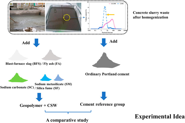
FIGURE 1. Experimental idea of this study.
This paper aimed to provide a new preparation method of cementitious materials containing CSW and the basic properties (flowability, setting times, and mechanical strengths) and microstructures (including X-ray diffraction/XRD, Fourier transform Infrared spectroscopy/FTIR, Thermal gravity analysis/TG-DTG, and Mercury intrusion porosimetry/MIP) of the geopolymer and the cement reference group were investigated. Then, the advantages and disadvantages of these two cementitious composites were discussed. The obtained geopolymer mixed with concrete slurry waste in this study provides new ideas and references for preparing a new type of cementitious material and is beneficial to recycling various wastes.
Blast-furnace slag (BFS), fly ash (FA), silica fume (SF), and P.O 42.5 ordinary Portland cement (OPC) were provided by China West Construction Hunan Group Co., Ltd., and the concrete slurry waste (CSW) with solid to water ratio of 1:1 was collected from the concrete mixing plant of the same company (CSW sedimented within 1 week). The particle size distributions of the raw materials are shown in Figure 2A), and the chemical compositions of these raw materials were determined by the X-ray fluorescence spectrometer (XRF), as shown in Table 1. As can be seen, there is high content of SiO2 and LOI value in the CSW, which implies that CSW contains much sand and some carbon particles/organic components (He et al., 2020). This is in line with the results of X-ray diffraction (XRD) and Fourier transform infrared spectroscopy (FTIR), as shown by Figure 2B). CSW is a well-crystallized substance with complex components, and there are complex bands ranging from 469 to 875 cm−1. It is worth noticing that the bands at approximately 1,089, 1,092, and 967 cm−1 in the CSW, FA, and BFS, respectively, represent the asymmetric stretching vibration of Si-O-T (T = Al or Si) and are closely related to the alkaline activation process (Hajimohammadi and van Deventer, 2017; Kaja et al., 2018). The commercial powdered activators used in this study were sodium carbonate anhydrous (Na2CO3/SC, AR, Purity≥99.8%) and sodium metasilicate pentahydrate (Na2SiO3•5H2O/SM, AR, modulus of 0.93). Silica fume (SF) with ultra-fine particle size, as depicted in Figure 2A), was expected to substitute the commercial silicon source (SM).
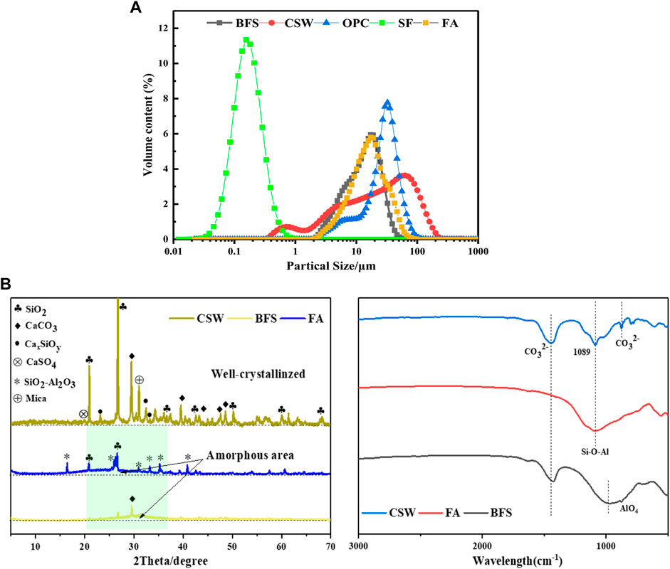
FIGURE 2. Basic characteristics of raw materials.
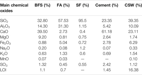
TABLE 1. Chemical compositions of raw materials by XRF.
To develop the filling effect of CSW, as reported by He et al. (He et al., 2020), and obtain a CSW-composite with dense microstructures, CSW was treated by wet-grinding before being added into the geopolymer and OPC(Tan et al., 2018). The grinding balls were made of zirconium silicate, and the mass ratio of the balls with different diameters (3 mm:2.5 mm:0.7 mm) equaled to 2:5:3. Moreover, the mass ratio of the balls and CSW (weight of the solids content) was 2.5:1. Then the grinding balls and CSW were poured into the machine for grinding (45 min). The parameters of the control cabinet were as follows: electric current for 7–10 A, voltage for 380 V, and frequency for 35–45 Hz. The wet-grinding CSW (pH = 11.0) with uniform particle size distribution was obtained when the separation of the balls and slurry was completed. The target size of homogenized CSW was consistent with the previous studies, D50 ≈ 3–5 μm (Tan et al., 2018; He et al., 2020).
Figure 3 shows the particle size distribution and SEM morphology of the homogenized CSW. It can be seen that the uniform particle size was obtained in the CSW, with a D50 of 3.757 μm. The SEM morphology shows that many fine particles with an angular shape and clusters scatter randomly, and there are many pores on the surface of those clusters. Besides, many smooth flake particles, identified as SiO2, embedded in those observed clusters.
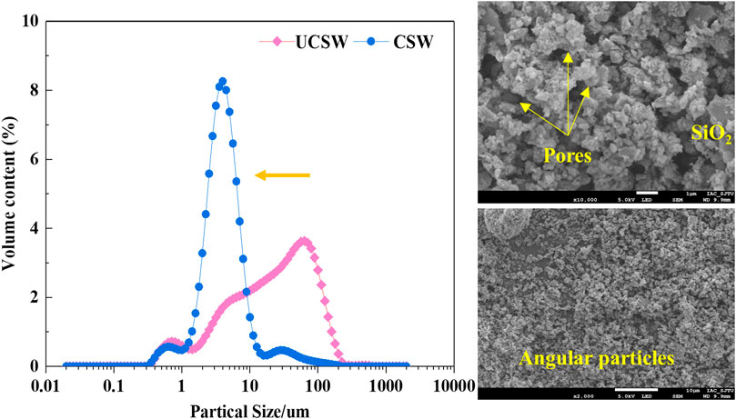
FIGURE 3. Particle size distribution and SEM morphology of the homogenized CSW.
Mix proportions of one reference group (cement + CSW, CCSW) and 11 geopolymer groups (geopolymer + CSW, GCSW) are shown in Table 2. The water to binder ratio (W/B) was kept at 0.5 in all specimens. The mass ratio of binders and CSW was 1:1, and the ratio of sodium carbonate and silicon sources (sodium metasilicate pentahydrate + silica fume) was kept at 1.5:1 (Ishwarya et al., 2019). Specifically, in the GCSW groups of No.1 to No.4, 9% sodium carbonate and 6% sodium metasilicate (total 15%, mass ratio of the binders) were utilized as the activators, and the effect of different binder proportions (fly ash and slag) was evaluated. The effect of activator dosages (10–25%) was investigated in GCSW groups of No.5 to No.8, and the influence of silica fume substitution for sodium metasilicate was explored in GCSW groups of No.8 to No.11.
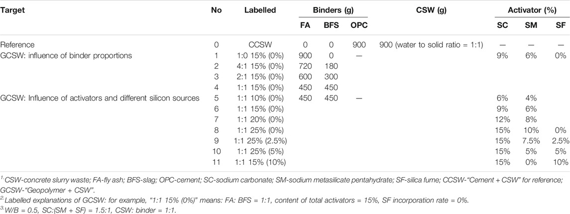
TABLE 2. Mix proportions of the 12 groups.
A cement mixer was used to prepare all the specimens. Firstly, the homogenized CSW was poured into the container and then mixed for 1 min at a rotation speed of 140 ± 5 r/min and revolution speed of 62 ± 5 r/min. Afterward, fly ash and slag were added into the CSW and mixed for another 2 min at a rotation speed of 280 ± 10 r/min and revolution speed of 125 ± 10 r/min. Secondly, the activators were wet mixed with the matrix obtained from above for 2 min. Finally, the homogenized matrix was completed and cast into 40 × 40 × 160 mm detachable steel prism molds immediately. Each specimen was prepared in triplicate. A vibrating table (1 × 60 shocks, one shock/s) was used to improve compactness and eliminate the air bubbles in the matrix. All the specimens were de-molded after 24 h and cured at 20 ± 1°C and 90% relative humidity for 3, 7, and 28-days tests.
Flowability of mixtures was tested by a conical mold (36 mm, 60 mm, and 36 mm) and a smooth glass plate. Before the homogenized matrix that got from the mixer was cast, it would be poured into the conical mold. When the conical mold was full of the matrix, the top surface of it would be scraped flat, and then the conical mold was lifted so that the matrix could flow freely on the surface of the plate. The flow diameter was defined as the mean values of two perpendicular directions. Setting times of the CCSW and GCSW were measured by a Vicat apparatus according to the standard ASTM C191. Compressive and flexural strengths were tested according to the standard ASTM C349. The flexural strength was measured on three specimens for each group, and the compressive strength was further measured on the rest of the six broken half-specimens. After completing the tests of 28-days, the pieces within dimensions of 15 mm × 15 mm × 15 mm were collected and immersed into the anhydrous ethanol for 3 days to stop the reactions. Then the pieces were dried at 40°C in a vacuum environment for 24 h. Thereafter, some of the pieces were ground and passed the 0.75 mm sieve for XRD, FTIR, and TG-DTG analysis.
FTIR was taken using Nicolet Nexus 410 FTIR Spectrometer Spectrum, and the data was collected in transmittance mode from 4,000 cm−1 to 500 cm−1 with an accuracy of 0.01 cm−1. The mineral phase analysis was launched with X-ray diffraction with Cu(Kα) source (XRD, German BRUKERD8 ADVANCE Diffractometer) at a scanning rate of 2°/min with the 2θ ranging from 5° to 80°. Thermal gravity analysis experiments (TGA, TGA5500) were conducted with 20 ± 2 mg powder under the nitrogen atmosphere and heated at 10°C/min from ambient temperature to 1,000°C. Besides, pore size characteristics of the CCSW and GCSW were tested by Mercury intrusion porosimetry (MIP, AutoPore IV 9500, America). The surface tension of Mercury was 485 mN/m, and the contact angle was 140°.
Figure 4 shows the flow diameters of CSW-composites. As can be seen, the flow diameter of CCSW is only 95 mm, which is significantly lower than that of the GCSW groups. This may be related to the morphology of CSW and the reaction characteristics between the two kinds of cementitious materials. In other words, CSW is mainly composed of many extremely porous, absorbent, and coarse clusters, as shown in Preparation of homogenized CSW. These clusters in the CSW can increase the friction between particles and reduce the local water-binder ratio by absorbing part of free water, thus weakening the flow performance of CCSW (He et al., 2020). Besides, due to the cement hydration, the free water was consumed, and the flow diameter of CCSW decreased furtherly. The flow diameters of GCSW groups fluctuate between 93 and 200 mm. When the level of activators is fixed at 15%, and the SF incorporation rate kept at 0%, the flow diameters of GCSW gradually decrease from 192 to 165 mm with the increase of BFS, which can be attributed to the existence of CaO and rough morphology of BFS (Ismail and El-Hassan, 2018). On the contrary, the flow diameters of GCSW are proportional to the dosages of activators. With the activators increase from 10 to 25%, the flow diameters of GCSW increase from 130 to 200 mm. As reported, with the increase of activators, more BFS and FA particles could be dissolved, and the particle concentration in the GCSW decreased accordingly. Thus the flow diameters of GCSW were improved (Ishwarya et al., 2019). Besides, when the SF incorporation rate keeps within 2.5%, the flowability of GCSW has an insignificant decrease. However, when the incorporation rate of SF reaches over 5%, a significant decrease in the flow diameter of GCSW could be observed. In particular, when SF completely replaces the SM (10% SF incorporation rate), the flow diameter of GCSW is almost equal to that of the CCSW. Ultra-fine SF particles have a large specific surface area, and the increase of SF content would increase the water requirement for the GCSW to reach the same flow diameter. Therefore, when the SF substitution rate exceeds a certain range, the flow performance of GCSW would suffer a significant loss. This result is consistent with the experimental conclusions obtained by Liu et al., 2020.

FIGURE 4. Flowability of the CCSW and GCSW (A: influence of slag; B: influence of activator and silica fume).
The results of the setting time are presented in Figure 5. After adding CSW to the OPC, the initial and final setting times of CCSW are reduced to about 80 and 145 min, respectively. As reported by Liu et al. (2019), He et al. (2020), the setting time of the cementitious system was greatly influenced by the filling effect and nucleation effect of CSW. On the one hand, CSW would replace the unhydrated substances in the CCSW to fill the pores inside the structure at an early stage, densifying the internal structure and facilitating the skeleton formation. On the other hand, CSW could also act as a nucleation site to provide contact sites for the connection of hydration products, while some of the hydration products contained in the CSW could induce and accelerate the reaction process of the OPC, thus accelerating the initial and final setting times (Soliman and Nehdi, 2011). Compared to CCSW, the initial and final setting times of GCSW fluctuate between 70-255 min and 115–300 min, respectively. For example, when the activator’s dosage is fixed at 15%, and the SF incorporation rate keeps at 0%, the setting times of GCSW are gradually shortened with the increase of BFS. This is due to the higher activity of BFS than FA, and the addition of BFS provides more CaO to GCSW, which can accelerate the reaction rate (Figure 5A). A similar situation can also be observed when the dosage of activators is increased. It can be seen from Figure 5B), when the dosage of activators is increased from 10 to 25%, the initial and final setting times of GCSW are shortened by about 63.16 and 53.06%, respectively. Increasing the dosage of the activators is equivalent to providing more Na2O to GCSW, which results in a higher pH value of pore solution in the GCSW groups, thereby increasing the dissolution and reaction rate of the raw materials (Yousefi Oderji et al., 2019). However, it is worth noticing that the setting times of GCSW can be gradually prolonged as the SF incorporation rate increases (0–10%), especially when the rate of SF exceeds 5%. The initial and final setting times of GCSW are almost equal to that of the pure OPC, reaching 180 and 215 min, respectively. On the one hand, it is speculated that, compared to SM, SF cannot provide additional Na2O, resulting in lower alkalinity of pore solutions. On the other hand, SF may have weaker solubility than SM under alkaline conditions, leading to more undissolved SF particles and hindering the connection of the generated alkali-activated products (Luukkonen et al., 2018a). Moreover, this phenomenon also explains the decrease of flow diameters of GCSW with high SF incorporation rates.
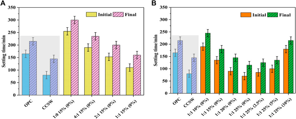
FIGURE 5. Setting times of the CCSW and GCSW (A: influence of slag; B: influence of activator and silica fume).
Figure 6 shows the compressive and flexural strengths of the hardened CSW-composites at 3, 7, and 28 days, respectively. For CCSW, the 3-days strength reaches 32.5 MPa with the addition of CSW to the cement, and increases to 40.2 and 43.6 MPa at 7 and 28 days, respectively. Moreover, the compressive strength of CCSW only increases by 8.46% during the curing period from 7 to 28 days. In the case of GCSW, the compressive strength increases with the increase of BFS. The 3, 7 and 28 days compressive strengths of GCSW without adding BFS are only 0.9, 3.4, and 4.9 MPa, respectively, whereas, when the mass ratio of FA to BFS reaches 1:1, the corresponding compressive strengths of GCSW increases to 19.4, 28.9, and 38.7 MPa, respectively, and its 28 days strength is almost the same as that of the CCSW. This indicates that the sodium carbonate type activator cannot effectively activate the precursors consisting of only FA and CSW particles under ambient temperatures, while the incorporation of BFS greatly enhances the reactivity of GCSW. According to the previous studies, the mechanical properties of geopolymer usually reach a more satisfactory level when FA: BFS is equal to 1:1 (Chen et al., 2015; Abdalqader et al., 2016). Besides, when the FA: BFS keeps at 1:1, and the SF incorporation rate is 0%, the variation of the activators also significantly affects the compressive strengths of GCSW groups. For instance, when the activators are reduced from 15 to 10%, the 3, 7, and 28 days strengths of GCSW decrease by 26.29, 29.41, and 24.40%, respectively. They reach 29, 41.1, and 60 MPa when the activators are increased from 15 to 25%, and the corresponding improvement rate reaches nearly 55.04%. The change in the strengths of GCSW is mainly attributed to the alkaline equivalent provided by the activators. With the increase of pH values, the dissolution of reactive species in FA and BFS increases, thus generating more products to improve specimens’ early and late strengths (Jeong et al., 2019). In addition, the type of additional silica source (activator) is also one of the most important parameters affecting the strength development of GCSW (Luukkonen et al., 2018b). It is worth noting that there is almost no adverse effect on the early strength of the GCSW group (3 and 7 days) with FA: BFS of 1:1 and activator dosage of 25%, when the SF incorporation rate reaches 2.5%. However, when the SF incorporation rate exceeds 5%, a significant reduction in the compressive strengths of GCSW is observed at all ages. This phenomenon is not difficult to be understood by combining the results of flow diameters and setting times of the corresponding specimens. Compared to commercial SM, the ability of SF to provide a soluble silicon source in an alkaline environment is limited, and its substitution rate should be kept within 5% (Luukkonen et al., 2018a).
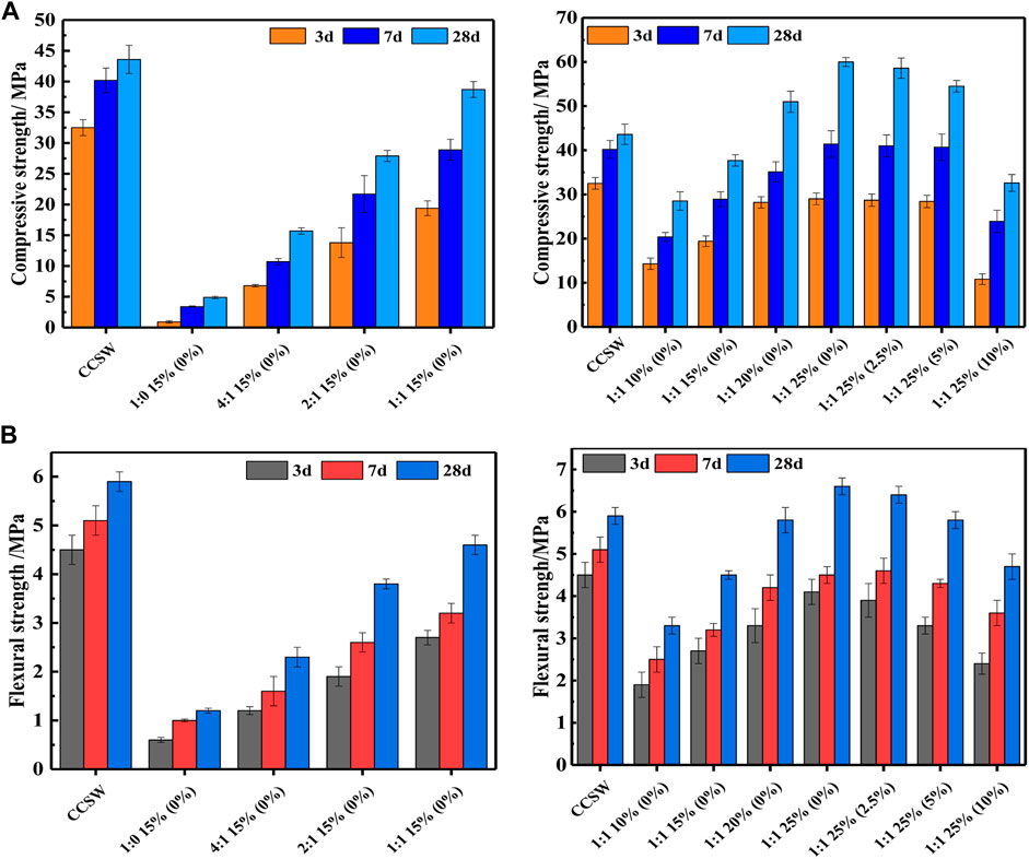
FIGURE 6. Mechanical performances of CCSW and GCSW composites.
The development of flexural strength is similar to that of compressive strength. The flexural strength could be effectively improved by increasing the content of BFS and activators. The 28 days flexural strength of GCSW increases to approximately 7 MPa when the FA: BFS is 1:1, and the dosage of activators is 25%. In this study, the set ratio of FA and BFS is scientific and reasonable because it was reported that the high-level content of BFS may cause severe shrinkage, which could leave many microcracks inside the specimen and have a negative effect on the flexural strength (Yousefi Oderji et al., 2019). Besides, the 28 days flexural strength of GCSW reaches the same level as CCSW when the FA: BFS is 1:1, and the activator’s dosage reaches 20%.
Figure 7 presents the XRD patterns of CCSW and typical GCSW, in which the main crystalline products of the CSW-composites can be observed when the 2θ ranged from 5 to 70° (Pan et al., 2018). Although the peak intensities of the minerals can reflect the relative content of particular phases, the XRD results were mainly used for qualitative analysis rather than quantitative analysis. Firstly, it needs to be noted that the peaks of quartz, calcium carbonate, and calcium-silica with different Ca/Si ratios in the CSW are still detectable in the CCSW and GCSW, which is consistent with the high crystallinity of CSW. For the CCSW, no new crystalline phases are observed, except for the cement hydration products (e.g., ettringite, gypsum, calcium silicate hydrate, and calcium hydroxide). In the GCSW, the XRD patterns show slight differences under the influence of BFS and activators. As for the GCSW with 15% activator, 0% BFS and 0% SF incorporation rate, a broad diffuse hump, and crystalline peaks of mullite and quartz are observed in the range of 20–40°2θ, which are mainly attributed to the nature of BFS and FA in the raw materials. Referring to the lowest mechanical strengths of the GCSW specimen, “1:0 15% (0%) ”, it can be inferred that the reaction degree of this specimen is still low at 28 days. Also, a high-intensity peak is detected at 28.8°2θ, which is identified as gaylussite (Na2Ca(CO3)25H2O) (Bernal et al., 2014). The formation of this phase indicates that a precipitate is preferentially formed due to the reaction between the carbonate and sodium ions released from the activators and the calcium ions dissolved from the precursors (FA, BFS, and CSW). However, such phases do not effectively enhance the strength of the GCSW, as shown by the mechanical strength of “1:1 15%, 0%” (Abdalqader et al., 2016). It is worth noticing that the peak intensities of both the mullite and gaylussite in the range of 25.0–30.0°2θ decrease as the content of BFS and activators increases, while the peak at 29.5°2θ increases significantly, suggesting a change in the composition of the main products in the GCSW groups. In particular, the peak at 29.5°2θ is identified as the calcium silicate hydrate (C-S-H) and calcium carbonate phases. The gaylussite’s intensity decrease may suggest the involvement of sodium and calcium ions in the formation of C-S-H (Samantasinghar and Singh, 2018). According to the previous studies, the formation of the C-(A)-S-H phase plays a key role in the early and final strength development of the geopolymer with FA-BFS as the main precursors (Ben Haha et al., 2011a). For instance, when the dosage of activators reaches 25%, and the SF incorporation rate is within 5%, the intensity of the peak located at 29.5°2θ is even more than that of the quartz peak located at 26.7°2θ, which is also in good agreement with the excellent mechanical strengths exhibited by the corresponding GCSW groups. When the SM is completely substituted by SF, the intensity of the C-S-H peak decreases and it is generally consistent with the reduction in the 28 days compressive and flexural strengths for the “1:1 25% (10%)” GCSW specimen. Furthermore, the hydrotalcite phase is usually detected in sodium carbonate-activated slag or slag/fly ash mixtures with a 2θ of 11.7°, however, it is difficult to be observed here, considering that the peak intensity of the hydrotalcite phase is too weak to determine its presence (Ben Haha et al., 2011b).
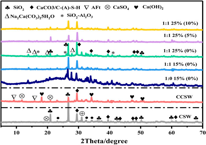
FIGURE 7. XRD for CCSW and GCSW composite.
Figure 8 illustrates the FT IR spectra of CCSW and typical GCSW groups. All specimens exhibit similar band characteristics, indicating a similar product composition. Major bands are detected at approximately 3,450, 1,650, 1,450, 1,080, 995, and 875 cm−1. The structure of interlayer water in GCSW and CCSW is characterized by the O-H stretching band located at around 3,450 cm−1, whereas the bending of the chemically bonded H-O-H is located at approximately 1,650 cm−1 owing to the water capture effect and surface absorption of the gel cavities (Ishwarya et al., 2019). Compared to CCSW, the absorption band due to chemically bonded water is barely visible in the GCSW specimen of “1:0 15% (0%)", suggesting that less alkali-activated products are produced, and the corresponding mechanical strengths of the specimen are the lowest. With the increase of BFS and activators, the absorption band of GCSW at 1,650 cm−1 is enhanced but still generally lower than that of the CCSW. The absorption bands at 1,450 cm−1 and 875 cm−1 are mainly caused by carbonates: In CCSW, it is mainly due to the existed calcium carbonate in the CSW and a small proportion of carbonized hydration products. As for the GCSW, these bands could be attributed to the presence of calcium carbonate and gaylussite detected in the XRD, and the excessive carbonate ions from the activators. It is worth noticing that the GCSW specimen of “1:0 15% (0%)" has a stronger absorption band at 875 cm−1 than that of the other GCSW specimens, and the intensity of this band gradually decreases with the increase of BFS and activators. Combined with the XRD results, it seems that the absorption band at such wavenumbers may be related to the formation and transformation of gaylussite. It is well known that the bands located at 950 cm−1 - 995 cm−1 are assigned to the Si-O vibration in C-S-H and also imply the formation of C-A-S-H (Puertas and Fernández-Jiménez, 2003). As can be seen from GCSW: On the one hand, the absorption band of C-A-S-H gradually shifts towards lower wavenumbers with the increase of BFS and activators, which is possibly affected by calcium ions and tetrahedral aluminum in the BFS or the more formation of C-A-S-H with short chains that could decease the network connectivity of alkali-activated products (Yang et al., 2012). On the other hand, the gradual enhancement of the C-A-S-H absorption band directly leads to a significant improvement in the mechanical properties of the GCSW specimens. Furthermore, it is interesting to notice that the characteristic absorption band of CSW at 1,080 cm−1, which could still be observed in CCSW, gradually disappears in GCSW with the continuous generation of C-A-S-H, as shown in the corresponding band of “1:1 25% (0%)”. It is speculated that some minerals in the CSW are also involved in the formation of alkali-activated products, such as mica-like minerals (Bassani et al., 2019). However, further investigation is still needed to be conducted.
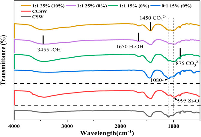
FIGURE 8. FTIR analysis for CCSW and GCSW composites.
Figure 9 shows four typical TG and DTG curves of CCSW and GCSW. There are mainly two mass losses in the DTG curves of GCSW composites, while three losses in CCSW, suggesting the difference in the production components of these two cementitious systems. As shown by the specimens of GCSW, two kinds of productions match well with two weight losses. The first mass loss is mainly at 110°C and ascribed to the evaporation of water existing in the pores of C-(A)-S-H gel (Ismail et al., 2013). The mass loss between 690°C and 727°C is owing to the decomposition of the bonded water in the stable carbonates, which come from the CSW and alkali-activated products, such as calcium carbonate and gaylussite detected by XRD and FTIR (Jin et al., 2014). Meanwhile, it should be noticed that the mass losses appearing in the CCSW are quite different from the GCSW. Firstly, the decomposition temperature of C-(A)-S-H gel in the CCSW (approximately 100°C) was lower than that of the GCSW (111°C–118°C). The evaporation of the bonded water in the AFm often occurs at around 160°C–200°C in the CCSW, whereas there is no mass loss in the same temperature range of GCSW. Secondly, the mass loss at 350–500°C is the typical sign belong to OPC, resulting from the decomposition of Ca(OH)2 (Suraneni et al., 2019). The mass loss at around 700°C in CCSW is primarily due to the decomposition of the carbonates from CSW, and a small part is attributed to the carbonized hydration products. It should be mentioned that, according to the TG curves, the mass loss of GCSW is basically less than that of CCSW, suggesting that the amount of chemically bonded water in GCSW is less than that of the CCSW, and it is in line with the corresponding analysis of FTIR section.
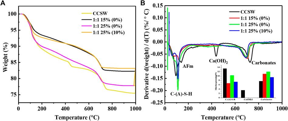
FIGURE 9. TG-DTG results of CCSW and GCSW composites (A: TG curves, B: DTG curves).
It is worth noticing that the mass-loss rate associated with C-(A)-S-H gel becomes sharper in “1:1 25% (0%)” than that of the “1:1 15% (0%)”. The mass loss percentage of the main production gel increases from 6.72% in “1:1 15% (0%)” to 10.27% in “1:1 25% (0%)” as shown by the small graph in Figure 9B, indicating a great number of C-(A)-S-H gel is produced, which is well in line with the best mechanical properties of the “1:1 25% (0%)” GCSW group. Besides, the outstanding mechanical performance is not only due to the increase of C-(A)-S-H gel, but also the increase of carbonates with high crystallinity and stability, as shown in the increase mass loss from the decomposition of the carbonates, which is from 10.99% in “1:1 15% (0%)” to 11.93% in “1:1 25% (0%)”. Moreover, a significant reduction of the mechanical properties in “1:1 25% (10%)” can also be explained by its DTG curve. The complete substitution of SF leads to a decrease of C-(A)-S-H gel dehydration, which is from 10.27% in “1:1 25% (0%)” to 7.35% in “1:1 25% (10%)”, as well as the decomposition of the carbonates, which is from 11.93 to 9.49%. The nearly overlapping TG curves and the similar C-A-S-H mass loss percentage of “1:1 15% (0%)” and “1:1 25% (10%) “also suggest that these two groups have similar mechanical properties. The weight loss may be closely related to the mechanical properties of GCSW.
The pore structure has been reported to be closely related to some basic properties of cementitious materials, such as mechanical properties and durability (Ahmad and Chen, 2018). Therefore, the pore structure distribution characteristics of CCSW and GCSW were tested, and the results are shown in Figure 10. It can be seen that the most probable aperture of CCSW and GCSW is significantly different from each other. GCSW specimens present the most probable apertures around 10 nm, while CCSW is mainly around 80 nm. This suggests that a denser pore structure is more likely to be obtained by combining CSW with the geopolymer prepared in this study. Although this result cannot imply that the GCSW always achieves higher mechanical strengths than that of the CCSW, it is still an essential reference for the later durability investigation of CSW-composites (Tan et al., 2019; He et al., 2020). The pore sizes of CSW-composites can be classified into the following four types: harmless pores less than 20 nm, less harmful pores of 20–50 nm, harmful pores of 50–200 nm, and much harmful pores of more than 200 nm (Tan et al., 2018). As can be seen from the percentages of the pore size distribution, 44.84% of the pores in CCSW belong to the harmful pores, and the percentage of the much harmful pores is also high, reaching 31.46%, which may explain the limitations of CSW recycling in the OPC system. On the contrary, most of the pore sizes in GCSW belong to the less harmful pores with the fluctuating percentage between 25.81 and 49.68%, which depends on the geopolymer’s design parameters. When the dosage of the activators is increased, the proportion of pores less than 20 nm in GCSW rises accordingly, and these pores mainly belong to the gel pores in C-A-S-H and play a major role in supporting the strengths of GCSW. The increase of the SF incorporation rate makes the pore structure of GCSW more complex. When the SF incorporation rate reaches 5%, the most probable aperture of GCSW becomes finer. However, as the rate reaches 10%, the most probable aperture develops towards coarse pores (40.36 nm). Overall, with the increase of SF, the proportion of gel pores appears to decrease, while the proportion of harmful pores tends to increase. And its corresponding decrease in the mechanical strengths of GCSW specimens can also be explained by the pore changes.
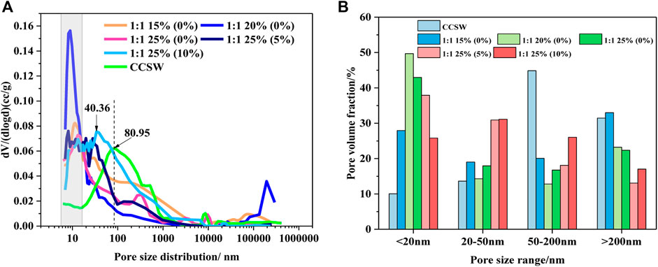
FIGURE 10. Pore characteristics of CCSW and GCSW composites (A: pore distribution, B: pore volume fraction).
Combined with the results of macroscopic and microscopic tests, this study clarified the reaction characteristics of CSW-based geopolymer. The properties of the prepared geopolymer were mainly related to the ratio of fly ash/slag, the amount of activator, and the type of silicon sources. The combined activator composed of sodium carbonate and sodium metasilicate is much moderate than the sodium hydroxide type. It is because when sodium carbonate touches the water-containing slurry, the carbonate ion is first released. At this time, the alkalinity of the reaction system is low, and the alkaline environment required for the early reaction is supported only by sodium metasilicate. Therefore, fly ash, as the dominant active raw material, is difficult to be stimulated. And the role of CSW particles is only to provide nucleation sites and fill the pores, which cannot facilitate strength development substantially. However, when the slag content and activator content increase, the activity of the raw material and the alkali equivalent of the system is improved, thus the reaction degree is intensified. The hydration of slag is accelerated, and the reaction rate of fly ash is improved. On the other hand, when silica fume is used in place of sodium metasilicate pentahydrate, the ultra-fine silica fume provides a soluble silicon source with the system in an alkaline environment forming C-A-S-H with calcium ions. But unlike the sodium silicate, silica fume does not provide additional sodium oxide, and its dissolution rate in the alkaline environment is much slower than that of commercial sodium silicate. Accordingly, the excessive replacement of silica fume will result in a lower alkali equivalent and higher particle concentration of the system, which leads to a decrease in the strength and flow diameter, and a prolonged setting time.
This paper showed an innovative way to recycle CSW, and a comparative study was made between the GCSW and CCSW in terms of the flowability, setting times, mechanical strengths, and microstructures (XRD, FTIR, TG-DTG, and MIP). The main conclusions are as follows:
1. With the addition of homogenized CSW into OPC and geopolymer, the flow diameter of CCSW is only 95 mm, while the GCSW could achieve higher flow diameters by adjusting the dosage of BFS and powdered activators (∼200 mm), and the flow diameter increases with the increase of the powdered activators. The negative effect on the flowability of the cementitious materials caused by CSW could be mitigated in the GCSW.
2. The setting time of the OPC is greatly shortened by the incorporation of CSW, with the initial setting time reduced from 165 to 80 min and the final setting time reduced from 215 min to 145 min. This is mainly due to the filling and nucleation effects of CSW. The setting time of GCSW is mainly affected by the content of BFS and activators. The initial and final setting times fluctuate between 70-255 min and 115–300 min, respectively, and the increase in both BFS and activators shortens the setting times of GCSW.
3. When BFS: FA keeps at 1:1, and the activator content reaches 15–20%, GCSW could achieve comparable mechanical strengths as the CCSW did at 28 days. The gained strengths of CCSW mainly come from the cement hydration products, while the GCSW is mainly supported by C-A-S-H and carbonates (calcium carbonate and gaylussite). The amount of chemically bonded water in the products of GCSW is lower than that of the CCSW.
4. Compared to CCSW, it is easier to obtain a dense microstructure by mixing the homogenized CSW with geopolymers prepared in this study. Increasing the dosage of BFS and activators could effectively increase the proportion of gel pores (< 20 nm) in the GCSW (25.81–49.68%). SF has a certain ability to replace SM, but the recommended incorporation rate for SF should be less than 5% without significantly affecting the fresh and hardened properties of GCSW.
5. In this study, the slag content is limited. Further increasing the slag content will greatly improve the mechanics and shorten the setting time. For satisfactory properties, the dosage of the activator should be 10–20% of the total amount of slag and fly ash, because excessive activator may cause the problems such as efflorescence and worried durability. If the silica fume substitution (0–10%) is considered, the activator content should not exceed 25%. It is an innovative attempt to recycle CSW into alkali-activated materials, which shows advantages compared with traditional cement materials.
The original contributions presented in the study are included in the article/Supplementary Material, further inquiries can be directed to the corresponding author.
YG: Conceptualization, Methodology, Funding acquisition, review and editing. KD: Methodology, Data curation, Writing-original draft, Funding acquisition, review and editing. SX: Funding acquisition, Conceptualization, Data curation. WZ: Resources, Methodology, review and editing.
The Authors gratefully acknowledge the financial support from the National Natural Science Foundation of China (51978080), Joint Fund of the National Natural Science Foundation of China and the China Civil Aviation Administration (U1833127), Hunan Province Innovation Foundation for Postgraduate (CX20190668), Natural Science Foundation of Hunan Province (2021JJ40602) and Scientific Research Project of Hunan Provincial Department of Education (20B014).
WZ was employed by the China West Construction Hunan Group Co., Ltd.
The remaining authors declare that the research was conducted in the absence of any commercial or financial relationships that could be construed as a potential conflict of interest.
All claims expressed in this article are solely those of the authors and do not necessarily represent those of their affiliated organizations, or those of the publisher, the editors, and the reviewers. Any product that may be evaluated in this article, or claim that may be made by its manufacturer, is not guaranteed or endorsed by the publisher.
Abdalqader, A. F., Jin, F., and Al-Tabbaa, A. (2016). Development of Greener Alkali-Activated Cement: Utilisation of Sodium Carbonate for Activating Slag and Fly Ash Mixtures. J. Clean. Prod. 113, 66–75. doi:10.1016/j.jclepro.2015.12.010
Adesanya, E., Ohenoja, K., Luukkonen, T., Kinnunen, P., and Illikainen, M. (2018). One-Part Geopolymer Cement from Slag and Pretreated Paper Sludge. J. Clean. Prod. 185, 168–175. doi:10.1016/j.jclepro.2018.03.007
Ahmad, M. R., and Chen, B. (2018). Effect of Silica Fume and basalt Fiber on the Mechanical Properties and Microstructure of Magnesium Phosphate Cement (MPC) Mortar. Constr. Build. Mater. 190, 466–478. doi:10.1016/j.conbuildmat.2018.09.143
Ali, M. B., Saidur, R., and Hossain, M. S. (2011). A Review on Emission Analysis in Cement Industries. Renew. Sustain. Energ. Rev. 15, 2252–2261. doi:10.1016/j.rser.2011.02.014
Askarian, M., Tao, Z., Samali, B., Adam, G., and Shuaibu, R. (2019). Mix Composition and Characterisation of One-Part Geopolymers with Different Activators. Constr. Build. Mater. 225, 526–537. doi:10.1016/j.conbuildmat.2019.07.083
Audo, M., Mahieux, P.-Y., and Turcry, P. (2016). Utilization of Sludge from Ready-Mixed concrete Plants as a Substitute for limestone Fillers. Constr. Build. Mater. 112, 790–799. doi:10.1016/j.conbuildmat.2016.02.044
Audo, M., Mahieux, P.-Y., Turcry, P., Chateau, L., and Churlaud, C. (2018). Characterization of Ready-Mixed concrete Plants Sludge and Incorporation into Mortars: Origin of Pollutants, Environmental Characterization and Impacts on Mortars Characteristics. J. Clean. Prod. 183, 153–161. doi:10.1016/j.jclepro.2018.02.155
Bassani, M., Tefa, L., Coppola, B., and Palmero, P. (2019). Alkali-activation of Aggregate Fines from Construction and Demolition Waste: Valorisation in View of Road Pavement Subbase Applications. J. Clean. Prod. 234, 71–84. doi:10.1016/j.jclepro.2019.06.207
Ben Haha, M., Le Saout, G., Winnefeld, F., and Lothenbach, B. (2011a). Influence of Activator Type on Hydration Kinetics, Hydrate Assemblage and Microstructural Development of Alkali Activated Blast-Furnace Slags. Cem. Concr. Res. 41, 301–310. doi:10.1016/j.cemconres.2010.11.016
Ben Haha, M., Lothenbach, B., Le Saout, G., and Winnefeld, F. (2011b). Influence of Slag Chemistry on the Hydration of Alkali-Activated Blast-Furnace Slag - Part I: Effect of MgO. Cem. Concr. Res. 41, 955–963. doi:10.1016/j.cemconres.2011.05.002
Bernal, S. A., Provis, J. L., Myers, R. J., San Nicolas, R., and van Deventer, J. S. J. (2014). Role of Carbonates in the Chemical Evolution of Sodium Carbonate-Activated Slag Binders. Mater. Struct. 48, 517–529. doi:10.1617/s11527-014-0412-6
Chen, C.-T., Nguyen, H.-A., Chang, T.-P., Yang, T.-R., and Nguyen, T.-D. (2015). Performance and Microstructural Examination on Composition of Hardened Paste with No-Cement SFC Binder. Constr. Build. Mater. 76, 264–272. doi:10.1016/j.conbuildmat.2014.11.032
Correia, S. L., Souza, F. L., Dienstmann, G., and Segadães, A. M. (2009). Assessment of the Recycling Potential of Fresh concrete Waste Using a Factorial Design of Experiments. Waste Manage. 29, 2886–2891. doi:10.1016/j.wasman.2009.06.014
Duxson, P., and Provis, J. L. (2008). Designing Precursors for Geopolymer Cements. J. Am. Ceram. Soc. 91, 3864–3869. doi:10.1111/j.1551-2916.2008.02787.x
Elyamany, H. E., Abd Elmoaty, A. E. M., and Elshaboury, A. M. (2018). Setting Time and 7-day Strength of Geopolymer Mortar with Various Binders. Constr. Build. Mater. 187, 974–983. doi:10.1016/j.conbuildmat.2018.08.025
Férriz Papí, J. A. (2014). Recycling of Fresh concrete Exceeding and Wash Water in concrete Mixing Plants. Mater. Construcc. 64, e004. doi:10.3989/mc.2013.00113
Hajimohammadi, A., and van Deventer, J. S. J. (2017). Characterisation of One-Part Geopolymer Binders Made from Fly Ash. Waste Biomass Valor. 8, 225–233. doi:10.1007/s12649-016-9582-5
He, X., Zheng, Z., Ma, M., Su, Y., Yang, J., Tan, H., et al. (2020). New Treatment Technology: The Use of Wet-Milling concrete Slurry Waste to Substitute Cement. J. Clean. Prod. 242, 118347. doi:10.1016/j.jclepro.2019.118347
Iizuka, A., Sasaki, T., Honma, M., Yoshida, H., Hayakawa, Y., Yanagisawa, Y., et al. (2017). Pilot-Scale Operation of a Concrete Sludge Recycling Plant and Simultaneous Production of Calcium Carbonate. Chem. Eng. Commun. 204, 79–85. doi:10.1080/00986445.2016.1235564
Ishwarya, G., Singh, B., Deshwal, S., and Bhattacharyya, S. K. (2019). Effect of Sodium Carbonate/Sodium Silicate Activator on the Rheology, Geopolymerization and Strength of Fly Ash/slag Geopolymer Pastes. Cem. Concr. Compos. 97, 226–238. doi:10.1016/j.cemconcomp.2018.12.007
Ismail, N., and El-Hassan, H. (2018). Development and Characterization of Fly Ash–Slag Blended Geopolymer Mortar and Lightweight Concrete. J. Mater. Civ. Eng. 30, 04018029. doi:10.1061/(asce)mt.1943-5533.0002209
Ismail, I., Bernal, S. A., Provis, J. L., Hamdan, S., and Van Deventer, J. S. J. (2013). Microstructural Changes in Alkali Activated Fly Ash/slag Geopolymers with Sulfate Exposure. Mater. Struct. 46, 361–373. doi:10.1617/s11527-012-9906-2
Jeong, Y., Kang, S.-H., Du, Y., and Moon, J. (2019). Local Ca-Structure Variation and Microstructural Characteristics on One-Part Activated Slag System with Various Activators. Cem. Concr. Compos. 102, 1–13. doi:10.1016/j.cemconcomp.2019.04.009
Jin, F., Gu, K., and Al-Tabbaa, A. (2014). Strength and Drying Shrinkage of Reactive MgO Modified Alkali-Activated Slag Paste. Constr. Build. Mater. 51, 395–404. doi:10.1016/j.conbuildmat.2013.10.081
Kaja, A. M., Lazaro, A., and Yu, Q. L. (2018). Effects of Portland Cement on Activation Mechanism of Class F Fly Ash Geopolymer Cured under Ambient Conditions. Constr. Build. Mater. 189, 1113–1123. doi:10.1016/j.conbuildmat.2018.09.065
Kou, S.-c., Zhan, B.-j., and Poon, C.-s. (2012a). Feasibility Study of Using Recycled Fresh concrete Waste as Coarse Aggregates in concrete. Constr. Build. Mater. 28, 549–556. doi:10.1016/j.conbuildmat.2011.08.027
Kou, S.-C., Zhan, B.-J., and Poon, C.-S. (2012b). Properties of Partition wall Blocks Prepared with Fresh concrete Wastes. Constr. Build. Mater. 36, 566–571. doi:10.1016/j.conbuildmat.2011.08.063
Liu, M., Tan, H., and He, X. (2019). Effects of Nano-SiO2 on Early Strength and Microstructure of Steam-Cured High Volume Fly Ash Cement System. Constr. Build. Mater. 194, 350–359. doi:10.1016/j.conbuildmat.2018.10.214
Liu, Y., Zhang, Z., Shi, C., Li, N., and Lei, L. (2020). Influence of Silica Fume on Performance of High-Strength Geopolymer. J. Chin. Ceram. Soc. 48 (11), 1689–1699. doi:10.14062/j.issn.0454-5648.20200234
Luukkonen, T., Abdollahnejad, Z., Yliniemi, J., Kinnunen, P., and Illikainen, M. (2018a). Comparison of Alkali and Silica Sources in One-Part Alkali-Activated Blast Furnace Slag Mortar. J. Clean. Prod. 187, 171–179. doi:10.1016/j.jclepro.2018.03.202
Luukkonen, T., Abdollahnejad, Z., Yliniemi, J., Kinnunen, P., and Illikainen, M. (2018b). One-part Alkali-Activated Materials: A Review. Cem. Concr. Res. 103, 21–34. doi:10.1016/j.cemconres.2017.10.001
Miller, S. A., Horvath, A., and Monteiro, P. J. M. (2016). Readily Implementable Techniques Can Cut Annual CO2 Emissions from the Production of concrete by over 20. Environ. Res. Lett. 11, 1–7. doi:10.1088/1748-9326/11/7/074029
Ng, C., Alengaram, U. J., Wong, L. S., Mo, K. H., Jumaat, M. Z., and Ramesh, S. (2018). A Review on Microstructural Study and Compressive Strength of Geopolymer Mortar, Paste and concrete. Constr. Build. Mater. 186, 550–576. doi:10.1016/j.conbuildmat.2018.07.075
Pan, Z., Tao, Z., Cao, Y. F., Wuhrer, R., and Murphy, T. (2018). Compressive Strength and Microstructure of Alkali-Activated Fly Ash/slag Binders at High Temperature. Cem. Concr. Compos. 86, 9–18. doi:10.1016/j.cemconcomp.2017.09.011
Peng, M. X., Wang, Z. H., Shen, S. H., Xiao, Q. G., Li, L. J., Tang, Y. C., et al. (2017). Alkali Fusion of Bentonite to Synthesize One-Part Geopolymeric Cements Cured at Elevated Temperature by Comparison with Two-Part Ones. Constr. Build. Mater. 130, 103–112. doi:10.1016/j.conbuildmat.2016.11.010
Puertas, F., and Fernández-Jiménez, A. (2003). Mineralogical and Microstructural Characterisation of Alkali-Activated Fly Ash/slag Pastes. Cem. Concr. Compos. 25, 287–292. doi:10.1016/S0958-9465(02)00059-8
Rughooputh, R., Rana, J. O., and Joorawon, K. (2017). Possibility of Using Fresh concrete Waste in concrete for Non Structural Civil Engineering Works as a Waste Management Strategy. KSCE J. Civ. Eng. 21, 94–99. doi:10.1007/s12205-016-0052-1
Samantasinghar, S., and Singh, S. P. (2018). Effect of Synthesis Parameters on Compressive Strength of Fly Ash-Slag Blended Geopolymer. Constr. Build. Mater. 170, 225–234. doi:10.1016/j.conbuildmat.2018.03.026
Shen, W., Liu, Y., Yan, B., Wang, J., He, P., Zhou, C., et al. (2017). Cement Industry of China: Driving Force, Environment Impact and Sustainable Development. Renew. Sustain. Energ. Rev. 75, 618–628. doi:10.1016/j.rser.2016.11.033
Singh, B., Ishwarya, G., Gupta, M., and Bhattacharyya, S. K. (2015). Geopolymer concrete: A Review of Some Recent Developments. Constr. Build. Mater. 85, 78–90. doi:10.1016/j.conbuildmat.2015.03.036
Soliman, A. M., and Nehdi, M. L. (2011). Self-accelerated Reactive Powder concrete Using Partially Hydrated Cementitious Materials. Mater. j. 108, 1–7. doi:10.14359/51683462
Sturm, P., Gluth, G. J. G., Simon, S., Brouwers, H. J. H., and Kühne, H.-C. (2016). The Effect of Heat Treatment on the Mechanical and Structural Properties of One-Part Geopolymer-Zeolite Composites. Thermochim. Acta 635, 41–58. doi:10.1016/j.tca.2016.04.015
Suraneni, P., Hajibabaee, A., Ramanathan, S., Wang, Y., and Weiss, J. (2019). New Insights from Reactivity Testing of Supplementary Cementitious Materials. Cem. Concr. Compos. 103, 331–338. doi:10.1016/j.cemconcomp.2019.05.017
Tan, H., Zhang, X., He, X., Guo, Y., Deng, X., Su, Y., et al. (2018). Utilization of Lithium Slag by Wet-Grinding Process to Improve the Early Strength of Sulphoaluminate Cement Paste. J. Clean. Prod. 205, 536–551. doi:10.1016/j.jclepro.2018.09.027
Tan, H., Nie, K., He, X., Guo, Y., Zhang, X., Deng, X., et al. (2019). Effect of Organic Alkali on Compressive Strength and Hydration of Wet-Grinded Granulated Blast-Furnace Slag Containing Portland Cement. Constr. Build. Mater. 206, 10–18. doi:10.1016/j.conbuildmat.2019.02.028
Thakur, A. K., Pappu, A., and Thakur, V. K. (2019). Synthesis and Characterization of New Class of Geopolymer Hybrid Composite Materials from Industrial Wastes. J. Clean. Prod. 230, 11–20. doi:10.1016/j.jclepro.2019.05.081
Vieira, L. d. B. P., and Figueiredo, A. D. d. (2016). Evaluation of concrete Recycling System Efficiency for Ready-Mix concrete Plants. Waste Manage. 56, 337–351. doi:10.1016/j.wasman.2016.07.015
Xuan, D., Zhan, B., Poon, C. S., and Zheng, W. (2016). Innovative Reuse of concrete Slurry Waste from Ready-Mixed concrete Plants in Construction Products. J. Hazard. Mater. 312, 65–72. doi:10.1016/j.jhazmat.2016.03.036
Yang, T., Yao, X., Zhang, Z., and Wang, H. (2012). Mechanical Property and Structure of Alkali-Activated Fly Ash and Slag Blends. J. Sustain. Cem. Based Mater. 1, 167–178. doi:10.1080/21650373.2012.752621
Ye, N., Yang, J., Liang, S., Hu, Y., Hu, J., Xiao, B., et al. (2016). Synthesis and Strength Optimization of One-Part Geopolymer Based on Red Mud. Constr. Build. Mater. 111, 317–325. doi:10.1016/j.conbuildmat.2016.02.099
Yousefi Oderji, S., Chen, B., Ahmad, M. R., and Shah, S. F. A. (2019). Fresh and Hardened Properties of One-Part Fly Ash-Based Geopolymer Binders Cured at Room Temperature: Effect of Slag and Alkali Activators. J. Clean. Prod. 225, 1–10. doi:10.1016/j.jclepro.2019.03.290
Keywords: concrete slurry waste, fly ash, slag, geopolymer, properties
Citation: Gao Y, Duan K, Xiang S and Zeng W (2021) Basic Properties of fly Ash/Slag -Concrete Slurry Waste Geopolymer Activated by Sodium Carbonate and Different Silicon Sources. Front. Mater. 8:751585. doi: 10.3389/fmats.2021.751585
Received: 01 August 2021; Accepted: 12 October 2021;
Published: 19 November 2021.
Edited by:
Tingting Zhang, Dalian University of Technology, ChinaReviewed by:
Ping Duan, China University of Geosciences Wuhan, ChinaCopyright © 2021 Gao, Duan, Xiang and Zeng. This is an open-access article distributed under the terms of the Creative Commons Attribution License (CC BY). The use, distribution or reproduction in other forums is permitted, provided the original author(s) and the copyright owner(s) are credited and that the original publication in this journal is cited, in accordance with accepted academic practice. No use, distribution or reproduction is permitted which does not comply with these terms.
*Correspondence: Yingli Gao, eWluZ2xpZ2FvNTA5QDEyNi5jb20=
Disclaimer: All claims expressed in this article are solely those of the authors and do not necessarily represent those of their affiliated organizations, or those of the publisher, the editors and the reviewers. Any product that may be evaluated in this article or claim that may be made by its manufacturer is not guaranteed or endorsed by the publisher.
Research integrity at Frontiers
Learn more about the work of our research integrity team to safeguard the quality of each article we publish.