
94% of researchers rate our articles as excellent or good
Learn more about the work of our research integrity team to safeguard the quality of each article we publish.
Find out more
ORIGINAL RESEARCH article
Front. Mater., 30 August 2021
Sec. Structural Materials
Volume 8 - 2021 | https://doi.org/10.3389/fmats.2021.739542
This article is part of the Research TopicSpotlight on China - Materials ScienceView all 14 articles
 Rongcheng Wang1,2
 Yang Zhao2Qing Chang2Fengshi Yin1*Xiaoming Wang2*Wenyu Wang2Zhiqiang Ren2Guofeng Han2
In this paper, the microstructure and mechanical properties of the SG-CuAl8Ni6 Ni-Al bronze straight wall were studied, which was fabricated by the cold metal transfer (CMT) arc additive manufacturing technology. This Ni-Al bronze cladding layer of SG-CuAl8Ni6 is composed mainly of α-Cu, residual β phase, rich Pb phase and κ phase. The microstructure of this multilayer single-channel Ni-Al bronze straight wall circulating presents the overall periodic law, which changes from fine cellular crystals, columnar crystals to dendritic crystals with the increase of the distance from the substrate. The Vickers hardness value of the Ni-Al bronze straight wall decreases with the distance of substrate are between 155 and 185 HV0.5. The microhardness and elastic modulus of the Ni-Al bronze specimen are 1.57 times and 1.99 times higher than these of the brass matrix, respectively. The ultimate tensile strength (UTS) of the straight wall in the welding direction and 45° downward-sloping is greater than that of about 550 MPa in the stacking direction, and the elongation value in the welding direction is the highest. With the increase in interlayer temperature, the grain size increased gradually, and the tensile strength decreases slightly.
Copper alloys, with its excellent thermal and electric conductivity as well as mechanical properties, are widely used in the electrical, lighting and machinery fields. They also have good corrosion resistance to seawater and marine organisms, and thus are suitable to manufacture parts in the shipbuilding industry (Wang et al., 2020a). And traditional manufacturing technology is difficult to realize the complex shape of copper alloy parts forming, resulting in high processing cost, low material utilization rate.
Additive manufacturing is a process of designing and fabricating layer by layer (Lamichhane et al., 2020; Mosallanejad et al., 2021), with a “bottom-up” characteristic and without restricting the production process of traditional process and complex shape structure (Tofail et al., 2017; Tang et al., 2021; Wang et al., 2016; Attar et al., 2020), which greatly improves the utilization of resources, reduces the costs of research and development (Aziz et al., 2021; Thompson et al., 2015; Ostovari Moghaddam et al., 2021), and is thus one of the key drivers for sustainable manufacturing, and a key strategy for circulation economy. Wang et al. (2021) used Laser Engineered Net Shaping technology, have prepared Ti-Ni-C gradient composites with high hardness and wear resistance, which can be used for equipment, size and cutting tools, Hunter Martin et al. (2020) achieved grain refinement when using the laser additive manufacturing process by adding Al3Ta and Al3Zr to aluminum alloy powder materials, and believed that the method could also be extended to other alloys such as iron, nickel and titanium alloys. It has been shown that Laser additive manufacturing technology can improve production efficiency, have high material utilization rate, small shrinkage, and can obtain parts with excellent performance (Zhang and Chen, 2019; Chen et al., 2021). This point of view is also proven by Wang et al. (2020), who used SLM technology to prepare Cu-15Ni-8Sn alloy forming parts that showed good strength and toughness. Electronic beam additive manufacturing technology can achieve the rapid forming of complex parts with a minimum of steps, and the resulting density of components is high (Zhang and Chen, 2019). Roman Laptev et al. (2019) used electron beam additive manufacturing technology to obtain a Ti-6Al-4V alloy with a higher dislocation density and microhardness than that achieved by casting method with the same material. Focused electron beam deposition technology has also been shown to achieve high precision and complex profile manufacturing (Mutunga et al., 2019). However, additive manufacturing process has drawbacks such as large residual stress and an uneven microstructure (Sanaei and Fatemi, 2021), and the higher heat input needed creating further problems. For example, in the comparative study of Surinder Singh (Singh et al., 2019) on 316 L stainless steel laser cladding layer on the surface of a pure copper, it was found that the cladding layer was produced with a large number of holes, porosity and other defects, meaning that the strength, density and thermal conductivity of the pure copper cladding layer was lower than those of the cold spaying pure copper coating, because the high heat input leads to particle melting, high local temperature, high cooling rate and diffusion of carbon element in the cross-section.
Cold metal transfer (CMT) technology optimizes the connection between the additive process and wire feeding. The control system receives the short circuit signal of the welding wire for feedback, and controls the contact between the welding wire and the matrix, thereby forming a cyclic additive process (Cadiou et al., 2020). In addition to the advantages of high deposition efficiency and having a wide range of applied materials (Tanvir et al., 2021), compared to the other two additive manufacturing technologies, this technology also has the advantages of arc stability, less heat input and fewer spatters. Compared with pulsed metal inert gas (pulsed-MIG) technology, CMT additive ER5183 was confirmed by Derekar et al. (2020) to have lower porosity. Kim et al. (2020) have studied on nickel-aluminum bronze made of CMT and proved that CMT arc additive manufacturing technology can obtain better performance than casting forming workpiece. Pranav et al. (Nikam et al., 2020) used CMT to fabricated an ER2594 alloy straight wall and found that the tensile strength was better along the welding direction than in the stacking direction, but the percentage elongation of the samples was opposite due to having more slip systems in γ-FCC austenite. Wang et al. (2020) used CMT technology to deposit a 316 L part onto a stainless-steel plate, and found that the multi-layer structure had a periodic structure in the stacking direction, in transverse stacking direction has two alternating structure which the one is the areas materials remelted with dispersed grain orientation, and the other one is the areas located at the overlapping areas of adjacent with concentrated grain orientations. The yield and tensile strengths of covering the remelting zone were higher than those in the overlapping zone, and both of them were superior to those in the stacking direction. The optimization of CMT technology is mainly achieved by applying pulses. Wu et al. (2019) used the double-wire CMT + P process to obtain the 316 L stainless steel multilayer, and found that asynchronous arc striking and extinguishing can improve the forming. Increasing the wire feeding and decreasing the welding speed can increase the deposition rate, but it will cause the crystalline grains coarser due to the heat accumulation and reduction in the mechanical properties. Xie et al. (2020) proved that a fine-sized straight wall of 316 L stainless can be obtained by applying a pulsed CMT + P process, and that the microhardness changes parabolic along the stacking direction.
At present, research on CMT additive manufacturing mainly focuses on the section structure and the properties of steel and aluminum alloy by optimizing process parameters. There are few research papers on the properties of the copper alloy cladding layer manufactured by CMT arc additive manufacturing. In this paper, the microstructure, microhardness, tensile properties and corrosion resistance of Ni-Al Bronze forming parts manufactured by CMT arc additive are studied.
The substrate used in this research is brass alloy with the dimensions of 200 × 100 × 10 mm, containing 0.15 Fe, 1.5–2.5 Pb, 34.3–38.3 Zn and Cu in balance (in wt%), which is produced by Shanghai Meipin Industrial Co., Ltd. The SG-CuAl8Ni6 nickel-aluminum bronze welding wire with a diameter of Φ = 1.2 mm (Beijing Yida Kuntai Technology Co., Ltd.) was used for the CMT arc additive manufacturing. The welding wire has the following composition: 8.5–9.5 Al, 3.0–4.0 Fe, 1.0–2.0 Mn, 4.0–6.0 Ni, ≤0.02 Pb, ≤ 0.2 Si, ≤ 0.1 Zn, and Cu in balance (all in wt%).
The CMT arc additive manufacturing system used in this research is the ArcMan600 arc additive manufacturing system from Nanjing Enigma Automation CO., Ltd. as shown in Figure 1A. Prior to CMT arc additive manufacturing, the oxide film on the substrate surface was removed by mechanical grinding and ultrasonic cleaning. The CMT arc additive process parameters used are listed in Table 1. Before the experiment, the mathematical model of the multilayer single-channel was established. The model was imported and automatically sliced according to the printing parameters to generate the printing path. Through the layout simulation and dynamic path simulation with an extremely high degree, the printing process is shown intuitively and visually. Based on the simulation of the printing process, a reciprocating additive method and five interlayer temperatures were selected to form up multilayer single-channel forming experimental specimens, 100, 150, 200, 250, and 300°C, respectively, with the dimensions of 150 × 10 × 90 mm, where, the interlayer temperature is controlled by the cooling time after the formation of the cladding layer, and the macro-morphology of the multilayer single-channel wall is shown in Figure 1B. The nickel-aluminum bronze straight wall line with five parameters was cut to obtain samples for metallographic, hardness, tensile and corrosion resistance experiments.
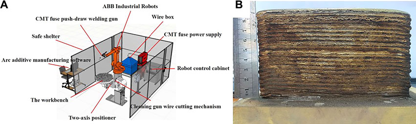
FIGURE 1. CMT arc additive manufacturing equipment (A) and macro morphology of the parts (B).
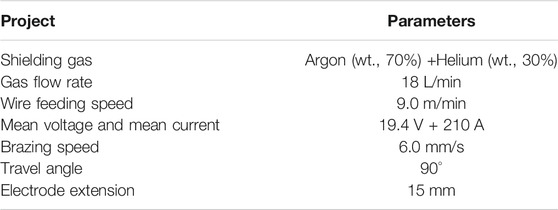
TABLE 1. The CMT brazing process parameters in the additive manufacturing process.
The SG-CuAl8Ni6 nickel-aluminum-bronze multilayer single-channel formation was cut using wire electro-discharge machine for a regional equidistant cutting, and a sample with a size of 5 × 5 × 3 mm was obtained, which was then polished. The microstructure of the polished section with and without corrosion by corrosive solution were observed using a quanta 250 field emission environmental scanning electron microscope (SEM, quanta 250, FEI, America). The corrosive solution was obtained by mixing 3 g FeCl3, 10 ml concentrated hydrochloric acid and 100 ml absolute ethanol solution.
Process parameters in Table 1 were used to obtain single-channel single cladding. X-ray diffraction (XRD, AXS D8 Advance, Bruker, Germany) was used to obtain XRD patterns of the cladding using Cu-K α radiation at a 2θ range of 10°–80° with a scan speed of 2 /min, and electron backscatter diffraction (EBSD, C-nano, Oxford Instruments, England) microstructural characterization was conducted using a JEOL 7001 F FE-SEM system equipped with a TSL/EDAX EBSD system containing a DigiView camera. These EBSD experiments were performed under a working distance of 15 mm at an acceleration voltage of 30 kV with a 70° tilt. After a process of argon ions polishing, the EBSD morphology of the bonding area between cladding layer and substrate, the inside of cladding layer and the top of cladding layer, were observed.
To evaluate the formation quality, some mechanical property tests were used for the CMT arc additive manufactured SG-CuAl8Ni6 nickel-aluminum-bronze multilayer single-channel wall.
The hardness of the SG-CuAl8Ni6 nickel-aluminum-bronze cladding specimen was measured using micro-hardness (MH-VK, China) at a load of 500 g with a dwell period of 15 s. Indentations were performed every 3 mm in the cladding layer area along the stacking direction. The inner area of the multi-layer single-channel formation was cut using wire electro-discharge machine cutting to obtain a sample of a size of 10 × 10 × 3 mm, and then polished. The nanoindentation test was conducted using a Nano Indenter (Agilent, G200, America) to measure the continuous load and displacement of each sample at five points by setting the maximum depth to 2,000 nm and holding the load time to 20 s, and thus the pressure depth-load curve was obtained.
Tensile tests were carried out on the sample at room temperature using a universal testing machine with a maximum 100 kN and a tensile rate ranging from 0.005 mm/min to 1,000 mm/min to determine the material’s characteristic value and the deformation capacity of the sample. In this experiment, three samples were tested by being subjected to a low strain rate of 1 mm/min to fracture the specimens. The size of the plate-like tensile specimen used in this test was obtained in accordance with the Chinese national standard GB/T 34505-2017 copper and copper alloys materials-tensile testing at room temperature. The elongation, tensile strength and yield of the sample were mainly tested, and after tensile testing, fracture morphology was observed by a quanta 250 field emission environmental scanning electron microscope (SEM).
The electrochemical test was performed on the brass alloy substrate and nickel-aluminum-bronze cladding. The size of the sample was 10 × 10 × 1 mm, and then AB glue was used to encapsulate the sample with a reserved working area of 1 cm2, after which absolute ethanol was used for cleaning. The electrochemical workstation (CHI-660E, CH Instruments Ins, America) was used to test the Tafel curve of the cladding layer and the substrate in 3.5% (mass fraction) NaCl solution (pH = 7). The electrochemical workstation adopts a standard three-electrode system, the working electrode is a copper alloy test sample, the auxiliary electrode is a platinum electrode, and the reference electrode is a saturated potassium chloride electrode. The polarization curve potential scan range is −1–1 V, and the scan rate is 0.5 mV/s.
Figure 2 shows the section morphology of the single-channel nickel-aluminum-bronze samples observed by Metallographic microscope. As shown in Figure 2A, there is a black arc between the CMT arc additive manufactured nickel-aluminum-bronze cladding layer and the substrate, which shows good metallurgical bonding between the two. The cladding layer’s internal microstructure presents an obvious gradient structure: the cladding layer and substrate combination area near the fusion line area of the microstructure are mainly for the tiny cell, in the region far away from the fusion line, columnar crystals grow perpendicular to the direction of welding (Figure 2A) and then gradually it turns to dendrites (Figure 2B). In the initial solidification stage, due to the low temperature of the base, the large temperature gradient of the melting pool in the binding region and small solidification speed are mainly small in the area near the melting line. With the solidification process, affected by the thermal diffusion, the base temperature gradually increases, the solidification temperature gradient at the solidification front decreases, and the microtissue is mainly presented as columnar crystals and branch crystal tissue growing in the reverse thermal dispersion direction. In Figure 2C, for the structure of the top of cladding, the direction of the temperature gradient is changed during the solidification process, the top of the solidification process is mainly affected by air cooling, the heat flow no longer runs perpendicular to the substrate surface, the temperature gradient is small, the solidification rate is high, thus a straight wall at the top of the regional direction dendrite tissue shows growth disorders, which are mainly for the branch crystal and the equiaxial crystal. It can be found that with the increase in the distance from the bonding zone, the grain size inside the cladding layer also gradually increases. This may be caused by the uneven solidification that takes place due to the different temperature gradients and undercooling degrees in the three regions, which in turn is caused by the heat dissipation of the air and matrix inside the cladding layer. Through a cross-sectional SEM observation, as shown in Figure 3A, bright white Pb particles with dispersion distribution can be identified inside the cladding layer. Due to the presence of a certain amount of Pb in the nickel-al-bronze alloy, monotectic crystals occur due to the influence of the high degree of undercooling during solidification, and the Pb-rich secondary phase particles are formed (Dong et al., 2019). Furthermore, the EDS analysis results (Figure 3B) and XRD analysis (Figure 3C) proved the existence of Pb phase.
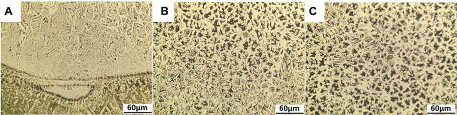
FIGURE 2. The phase diagram of section of single-channel nickel-aluminum-bronze cladding layer manufactured by CMT arc additive (A), the internal (B) and the top (C) of cladding layer.
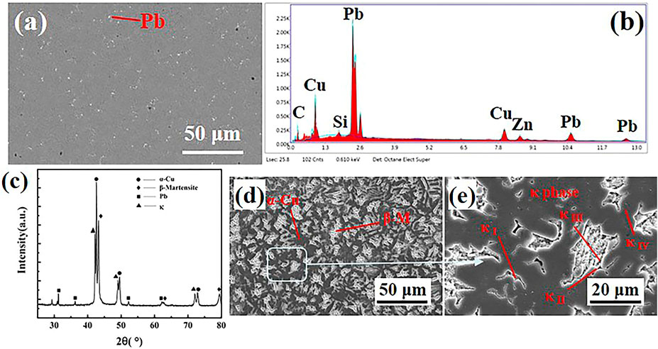
FIGURE 3. Internal backscattered electron image (A) and EDS analysis (B) of cladding layer before corrosion, and the XRD diffraction pattern (C), secondary electron images (D,E) of the single-channel nickel-aluminum-bronze cladding layer.
Figure 3C shows the XRD diffraction pattern of the single-channel nickel-aluminum-bronze cladding layer. The analysis shows that the inner part of the cladding layer is composed of α-Cu, residual β phase (Martensite) (β-M), Pb and K phase at room temperature, as shown in Figures 3D,E, the cladding layer presents a duplex microstructure composed of the gray α-Cu phase matrix and the bright white β-Martensite. The process of additive manufacturing is the nickel-aluminum-bronze metal wire end melt and spread out quickly on the substrate, and then rapid solidification. The main process from liquid solidification to room temperature is as follows: Firstly, α, κⅠ and β phase are precipitated in the liquid phase, α phase is the Cu-based solid solution with face-centered cubic structure, κⅠ phase is mainly flower-shaped, and β phase is martensite with 2R and 3H structure. As the solidification process proceeds, κⅡ phase is precipitated in the β phase and distributed around the α phase, mainly in the shape of spherical or flower, then the tiny spherical κⅣ phase precipitates out of the α phase, and then the β phase underwent eutectoid transformation: β→α+κⅢ, the κⅢ phase with spherical or layered structure.
The EBSD analysis results of the bonding area between the substrate and the cladding layer, the inner area of the cladding layer and the top area of the cladding layer, are shown in Figure 4, respectively. According to the phase distribution diagrams of different regions (Figure 4(A-a)-(C-a)), the structure is mainly α-Cu phase and residual β phase, α-Cu phase and β phase are labeled in red and blue, respectively. And the proportion of β phase is 6.74% in the bonding zone, 15.1% in the interior and 13.7% at the top, respectively. Due to the influence of substrate and air heat dissipation during the solidification of cladding layer, the cooling rate in the bonding zone and the top zone is higher than that in the interior, the growth tendency of α phase in the interior is weakened, at the same time, the eutectoid transformation time of β-phase is short and the content of β-phase is high in the cladding layer. From the grain boundary orientation diagram (Figure 4(A-b)-(C-b)), and the anti-pole diagram of α-Cu texture (Figure 4(A-c)-(C-c)), it was obtained are equiaxed or nearly equiaxed in the near the bonding region and the top grains, the region away from the fusion line is columnar crystal and the inner region is mainly dendrite. And it can be seen that in the Cu phase, the grains have a strong alignment in the direction of the <001> crystal, and the texture in the sample decreases and then increases with the distance from the matrix, which means that the grain growth rate on the grain orientation decreases and then increases with the distance from the matrix. Figures 4(A-d,e)-(C-d,e) is the histogram of grain orientation difference, and it can be seen that the orientation difference of β phase in the cladding layer is the largest in the inner region, and the internal grains of Cu-phase gradually increase with the distance from the matrix. In summary, with the increasing distance from the matrix, the grain size inside the cladding layer gradually increases, and the content of β phase solid solution increases first and then decreases (Chai et al., 2017; Chen et al., 2019a; Chen et al., 2019b).
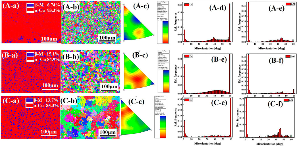
FIGURE 4. The EBSD analysis results of the bonding area between the substrate and the cladding layer (A), the inner area (B) and the top area (C) of the cladding layer, where (a) phase distribution diagrams, (b) grain boundary orientation diagram, (c) the anti-pole diagram of texture (d–e) the histogram of grain orientation difference.
Based on the EBSD test results from the single-channel nickel-aluminum-bronze cladding layer, the microstructures of the samples manufactured by CMT arc additive in the direction of height were analyzed. The metallographic after corrosion was shown in Figure 5, and the internal structure of the straight wall is similar to that of the single cladding. Figure 5A shows the bonding zone between cladding layer and substrate, which, due to a low substrate temperature, have a bigger molten pool internal temperature gradient, to form the branch crystal because of the large undercooling degree. The bonding zone structures of the middle area of the wall shown in Figure 5B, it can be seen that on to the next layer of the material, by the arc found on a layer of cladding layer at the top of the remelting pool formation, it was suffering from the melting solidification effect. Above the remelting zone is mainly composed of small dense isometric and it reverses the growth of the heat flow direction’s short columnar grain structure, leading away from the area, while the smaller branches of crystal formation are found in the forefront of the columnar crystal. Combine with the internal area structure of cladding layer of the central straight wall along the height direction (Figures 5D–F), it was found that the internal regional organizations of the straight wall appear in turn as dendrites, fine isometric, tiny columnar crystal, bulky columnar crystal and crystal growth direction and disorderly branch organization. Furthermore, when compared to the bottom of the organization, it can be seen that the size slightly increases. Combine with Figure 2, it can be conclusion that, the microstructure of the straight wall shows periodic. The formation of straight wall is the result of layer by layer accumulation. The temperature gradient and overcooling degree of each cladding are consistent with the single cladding fusion cladding, and due to the same temperature control in the accumulation process, the internal temperature gradient of each cladding changes the same. However, due to the influence of the heat dissipation mode, the heat dissipation speed slows down with the additive height increases, and the growth time increases, and the average grain size of each cladding gradually increases away from the substrate.
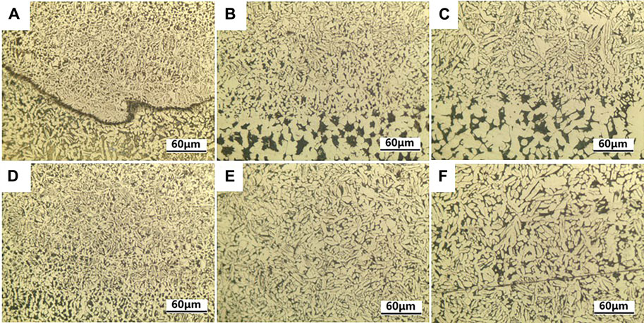
FIGURE 5. When the interlayer temperature is 100°C, the microstructure of the CMT arc additive Ni-Al bronze straight wall along the height direction shows that (A,B) is the area near the matrix of the straight wall, (C,D) is the middle area of the wall, and (E,F) is the top area of the wall.
As shown in Figure 6, an observation of the different interlayer temperature microstructure cladding layers within the same height, when the interlayer temperature was 300°C, the specimen’s microstructure size was bigger than that at 100°C. With the increase of interlayer temperature, the preheating effect of the previous cladding layer is increased, and the growth time of microstructure is increased, which makes the microstructure size gradually increase with the increase of interlayer temperature.
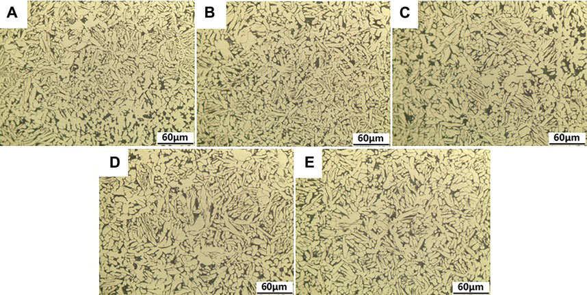
FIGURE 6. The microstructure morphology of CMT arc additive nickel-aluminum-bronze along the height direction at different interlayer temperatures, (A) 100°C, (B) 150°C, (C) 200°C, (D) 250°C, (E) 300°C.
The process of solidification and the cooling rate for the grain shape and size of the nickel-aluminum-bronze cladding layer presents the characteristics of directional solidification, and the grain growth direction and heat flow are in the opposite direction, mainly influenced by the temperature gradient. Adding the material in the manufacturing process is influenced by the arc’s heat effect, and the fast wire ends and substrate molten pool formation will be achieved. Due to the low substrate temperature of the brass alloy and itself having good heat conduction effect, the interface formed within the molten pool is greater than the cold, and the setting rate is low. At this time, the substrate junctions in the cladding layer are mainly composed of a thin layer of cell crystal. As the solidification process continues, the temperature of the matrix and the planar crystal region continuously increases, while the temperature gradient of the solid-liquid interface decreases. At this time, the solidification rate is faster and the columnar crystals grow in the opposite direction to the heat flow in the solidification and crystallization process. As the solidification process further continues, the components in the liquid metal become more undercooled, fine secondary dendrites are laterally formed at the front of the columnar grain, and the growth direction of the dendrite runs in the direction of the reverse heat flow. The inner cladding layer and the upper region growing direction that works for directional performance results from the copper alloy thermal conductivity, excellent bonding pads on the bottom of the cladding layer and solidification. Temperature gradient is reduced to a small scope, the heat flow no longer runs perpendicular to the substrate surface, and there is a fast solidification, thus the internal cladding layer and the upper area direction dendrite tissue show growth disorders, which are mainly in the branch crystal and the equiaxial crystal. This is different from Fe49.5Mn30Co10Cr10C0.5 multicomponent alloy (Chew et al., 2021) and Al-Co-Cr-Fe-Ni high entropy alloy (Shen et al., 2021), as the room temperature for the microstructure of Ni-Al bronze manufactured by CMT arc additive contains a large amount of dendritic microstructure. The increase of the interlayer temperature reduces the temperature gradient during the solidification process of the molten metal and extends the cooling time. Samples with a high interlayer temperature have a larger grain size.
The obtained hardness changes of the straight wall are shown in Figure 7. The internal hardness of single channel cladding layer is shown in Figure 7A, it can be seen that the hardness in the bonding zone increases significantly and the internal hardness is stable. It can be seen that the Vickers hardness values of the Ni-Al bronze straight wall are between 155 HV0.5 and 185 HV0.5 from Figure 7B, which are all higher than the average Vickers hardness values of the matrix of 123.7 HV0.5. The hardness of the cladding layer at the bottom of the straight wall is high, and Vickers hardness fluctuates and decreases with the increase of the distance from the bottom. The reason for this phenomenon is that when the next layer of additive manufacturing is carried out, the upper layer of the cladding layer will undergo a remelting solidification, and at this time, the temperature gradient is large and the solidification rate is fast, so metallurgical bonding occurs at the bonding interface and leads to the formation of compact and fine structures, which means that the hardness of the interlayer bonding is high, as hardness increases in this region. At the bottom of the straight wall, due to the strong heat conduction of the substrate and the large temperature gradient, the cooling speed of the first few cladding layers is extremely fast, so the obtained microstructure is fine, uniform and dense, and the obtained hardness is higher. With the increase of the number of additive layers, the solidification heat dissipation of cladding layer is mainly transmitted by air heat dissipation and the previous cladding layer, which is weakened by the heat conduction of matrix and reduces the cooling rate. After solidification, the internal structure of cladding layer is coarsened and the Vickers hardness is reduced.
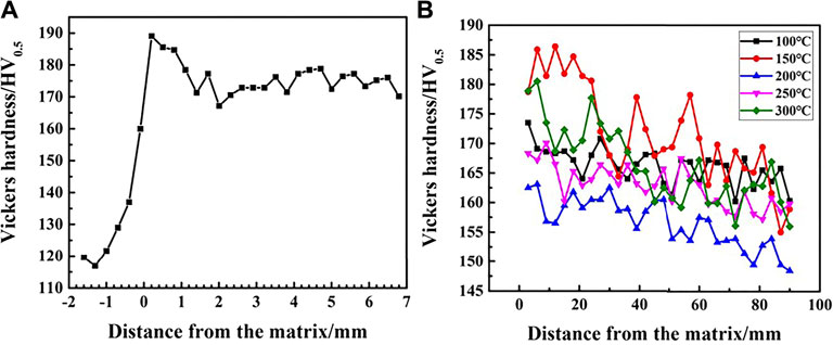
FIGURE 7. The Vickers hardness of the nickel-aluminum-bronze cladding, (A) the single-channel Ni-Al bronze cladding layer (B) the multilayer single-channel forming.
The depth-load curve of the sample in the central area of the straight wall is shown in Figure 8, and the obtained elastic modulus and hardness data are shown in Figure 9. As can be seen from Figure 8, under the condition of the same depth of pressure, the maximum load obtained by the Ni-Al bronze straight wall is about 200 mN, which is significantly higher than the that of brass matrix of 140 mN. It can be seen from Figure 9 that the average microhardness of Ni-Al bronze straight wall is 2.40 GPa and that of the brass matrix is 1.53 GPa at different interlayer temperatures, indicating that the Ni-Al bronze straight wall is harder than brass matrix, and the microhardness of the Ni-Al bronze straight wall is 1.57 times higher than that of the brass matrix. The Ni-Al bronze straight wall’s average elastic modulus is 122.79 GPa, while that of the brass matrix is 61.83 GPa. The elastic modulus of the Ni-Al bronze straight wall is 1.99 times higher than that of the brass matrix. The microhardness and elastic modulus of the Ni-Al bronze straight wall have no obvious rule to follow at different interlayer temperatures, and the process parameters of the surface interlayer temperature have no obvious effect on it.
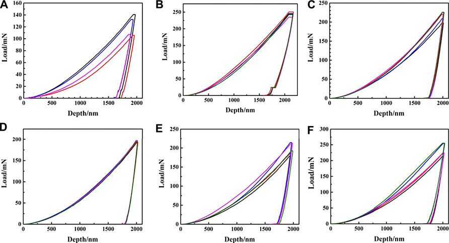
FIGURE 8. The internal of the CMT arc additive nickel-aluminum-bronze depth-load curve at different interlayer temperatures, where (A) the substrate, (B) 100°C, (C) 150°C, (D) 200°C, (E) 250°C, (F) 300°C.
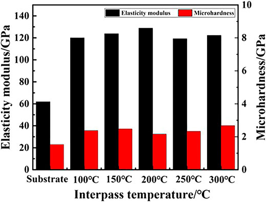
FIGURE 9. Hardness and elastic modulus of brass substrate and CMT additive nickel-aluminum-bronze straight wall.
As shown in Figure 10, the straight wall tensile samples for a straight wall inside different direction tensile samples of the stress-strain curve show no obvious yielding point to generate 0.2% of the residual deformation stress value as its yield strength Rp0.2. Along with the loading process and with the load increasing more than the material yield strength’s Rp0.2, a deformation of the tensile specimen elastic occurred first, and then the specimen tensile process reached the plastic deformation stage, until the end of the straight wall tensile specimen fractured due to the plastic deformation, and the straight wall came under different interlayer temperature parameters, as opposed to the three directions of yield strength, tensile strength and elongation, as shown in Table 2. Combined with Figure 10, it can be seen that the welding direction and 45° downward-sloping direction for the specimen’s tensile strength value, which were all at about 570 MPa, accumulated a significantly higher direction than the sample and the tensile strength of 550 MPa. Among them, the average elongation on the stacking direction, welding direction and 45° downward-sloping direction was 41.14, 54.00, and 41.04%, respectively, showing that the direction of welding in the specimen elongation value is the highest, but that the upward tensile specimen elongation is much higher than the known brass C35300 matrix 440 MPa tensile strength and its elongation of 25%. The tensile strength and elongation of the brass matrix were optimized by CMT arc additive Ni-Al bronze straight wall. By observing the longitudinal profile of the fracture running at the stacking, welding and 45° downward-sloping of the tensile samples at an interlaminar temperature of 100°C, as shown in Figures 11A–C, and the tensile samples’ fracture location in the direction of accumulation is the internal interlaminar junction of the straight wall, while the fracture in the 45° downward-sloping direction is also inclined to the direction of the interlaminar junction.
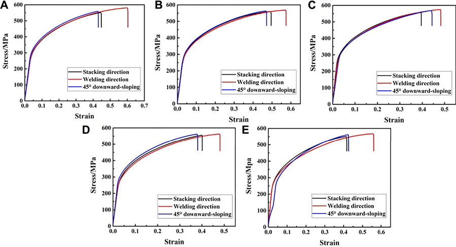
FIGURE 10. Tensile curves of a nickel-aluminum-bronze straight wall in different directions, where the interlayer temperature (A) 100°C, (B) 150°C, (C) 200°C, (D) 250°C, (E) 300°C.
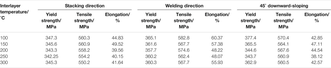
TABLE 2. Tensile properties of CMT arc additive nickel-aluminum-bronze multilayer single-channel forming at different interlayer temperatures.
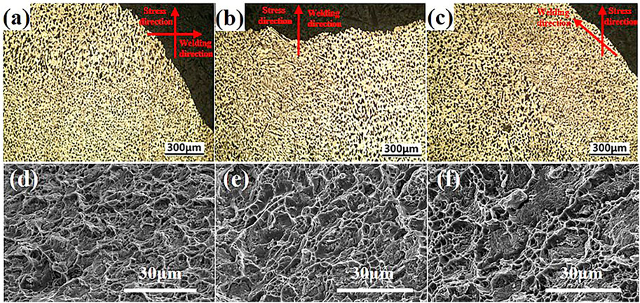
FIGURE 11. Longitudinal section of the macroscopic fracture of the tensile specimen in the stacking direction of the nickel-aluminum-bronze straight wall with an interlayer temperature of 100°C, where (A) stacking direction, (B) welding direction, (C) 45° downward-sloping , and SEM morphology of tensile fractures in three directions of a nickel-aluminum-bronze straight wall with an interlayer temperature of 100°C, where (D) parallel to the stacking direction, (E) parallel to the welding direction, (F) 45° downward-sloping.
Taking an interlayer temperature of 100°C as an example, the tensile fracture SEM morphology of the Ni-Al bronze straight wall in the stacking direction, welding direction, and 45° downward-sloping is shown in Figures 11D,E. From the diagram, it can be observed that the section is composed of tearing edges and oval dimples. And the dimples in the tensile specimen in the stacking direction are dense and the size is small, while the dimples in the welding direction are deeper and the size is larger, and their toughness is better than that in the stacking direction. By comparing the tensile samples along the welding direction’s fracture morphology at different interlaminar temperatures in Figure 12, it can be found that with the increase of interlaminar temperatures, the size of the dimples inside the tensile fracture of the Ni-Al bronze straight wall slightly decreases, tensile properties deteriorate accordingly.
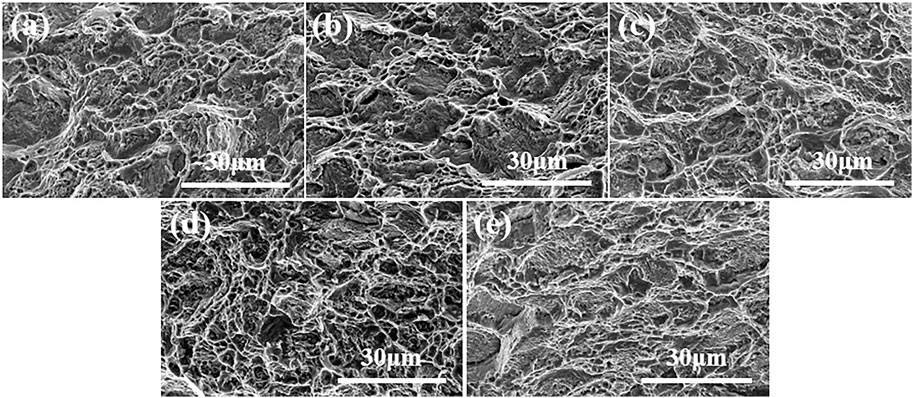
FIGURE 12. The SEM morphology of the tensile fracture of the nickel-aluminum-bronze straight wall along the welding direction at different interlayer temperatures, where (A) 100°C, (B) 150°C, (C) 200°C, (D) 250°C, (E) 300°C.
The formation process of the straight wall is composed of a layer-by-layer accumulation process, and the strength of the bonding zone between layers is low, being in fact lower than the overall tensile strength of the remelted solidified alloy. In other words, the tensile strength of the samples in the direction of accumulation is weakened by the influence of the interlayer bonding strength. C. Wang et al. (2020) studied the performance of the 316 L wall and found that it has a multi-layer structure. They studied the strength of the remelting and overlapping zones, and found that the yield strength and tensile strength of overlapping zone were low, while the strength of the stacking direction was the lowest. Pranav et al. (Nikam et al., 2020) found that the mechanical properties along the welding direction were better, which also proved this point of view. The internal structure of the straight wall is slightly increased by the increase of interlaminar temperature, but the size increase is very small, and the strength of the bonding zone is slightly reduced by the increase of interlaminar temperature. As a result, the tensile strength of the Ni-Al Bronze straight wall has a tendency of decrease with the increase of interlaminar temperature.
The obtained Tafel curve is shown in Figure 13, and the fitting results of the polarization curve are shown later. The self-corrosion potential of the wall is −0.32, −0.33, −0.31, −0.32, and −0.35 V at different interlayer temperatures (100, 150, 200, 250, 300°C), the current density of the self-corrosion current is 1.04 × 10⁻⁵, 1.41 × 10⁻⁵, 1.31 × 10⁻⁵, 1.20 × 10⁻⁵, 1.10 × 10⁻⁵ A/cm2, the self-corrosion potential of the brass substrate is −0.55 V, the self-corrosion current density of the brass substrate is 5.37 × 10⁻⁵ A/cm2. The self-corrosion potential of the Ni-Al bronze wall is increased by 0.20–0.24 V compared with that of the brass matrix, and the self-corrosion current density of the Ni-Al bronze wall is decreased by 4 × 10⁻⁵ A/cm2 compared with that of the brass matrix. It can be seen that the corrosion resistance of the nickel-aluminum-bronze straight wall is better than that of the brass matrix. By comparing the Tafel curves of the nickel-aluminum-bronze wall with the corrosion potential and the corrosion current density, it is found that there is no obvious increase or decrease rule, and the surface interlayer temperature has no obvious effect on the corrosion resistance of the straight wall material. As shown in Figure 13, the polarization curves of Ni-Al bronze samples and brass matrix samples are divided into anode and cathode regions. The cathode region is mainly characterized by a hydrogen evolution reaction, while the anode region is mainly characterized by three stages of the Ni-Al bronze corrosion process. First of all, copper in Ni-Al bronze alloy loses electrons to form Cu+ by anodic action and Cl− in electrolyte reaction to form CuCl and CuCl2−, which is shown by the increase in corrosion current density. Following this, due to the instability of CuCl, the dense Cu2O oxide film is formed by hydrolysis reaction 2CuCl + H2O→2Cu2O+2HCl. Finally, with the increase of polarization potential, a new electrode reaction is initiated, which results in a rapid increase of corrosion current density.
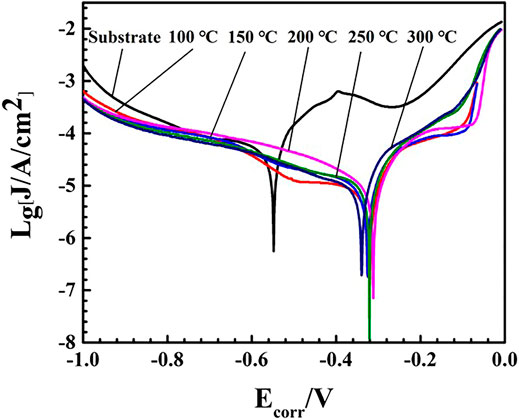
FIGURE 13. The Tafel curve of a nickel-aluminum-bronze straight wall with a brass substrate and different interlayer temperatures.
A more positive the self-corrosion potential leads to a more difficult anodic polarization. The current density of self-corrosion reflects the speed of the corrosion reaction of the material. A smaller current density of self-corrosion results in a slower material’s corrosion reaction. Without too many defects in the material, the corrosion resistance of the material is only related to the property of the material itself. The self-corrosion potential of the nickel-aluminum-bronze alloy is greater positive than the matrix, and the corrosion current density is thus smaller, meaning that the corrosion resistance is better than that of the brass matrix.
In this study, the microstructure and mechanical properties of an as-built SG-CuAl8Ni6 part manufactured by CMT wire and arc additive manufacturing were discussed in detail. The conclusions can be summarized as follows:
1) The Ni-Al bronze cladding layer of Sg-CuAl8Ni6 is mainly composed of α-Cu, residual β phase, Pb and κ phases. The microstructure of the single-channel Ni-Al bronze cladding has obvious gradient structure, which is successively presented as peritectic, columnar crystals growing in the direction of heat flow, dendritic crystals growing in the direction of disorderly growth, and equiaxed grains. With the increase of the distance between the cladding layer and the matrix, the grain size inside the cladding layer increases gradually, and the content of β phase solid solution increases first and then decreases. In its structure, the microstructure of the monolayer of the multilayer and multi-pass Ni-Al bronze straight wall is similar to that of the monolayer single channel.
2) The Vickers hardness values of the Ni-Al bronze straight wall are between 155 and 185 HV0.5, and the hardness of the wall overall trend of fluctuation decreases with the distance of substrate, and the hardness of single cladding in the bonding zone increases significantly and the internal hardness is stable. The obtained straight wall in the central area of the nano indentation test results show that the nickel-aluminum-bronze straight wall can achieve a maximum load that is controlled in 200 mN, which is higher than the brass substrate (140 mN). At the same time, the nickel-aluminum-bronze sample microhardness is 2.40 Gpa, and its modulus of elasticity is 122.79 Gpa. Its microhardness was 1.57 times of the brass substrates (1.53 Gpa), and the brass modulus of elasticity (61.83 Gpa) of 1.99 times, which is again better than that of the matrix.
3) The fracture of the straight wall tensile specimen is a ductile fracture, and its fracture morphology is mainly composed of tearing edge and oval dimples. The location of the fracture on the stacking direction is mainly concentrated in the combination area, and the tensile strength in the combination area is weak. The tensile strength of the straight wall in the welding direction and 45° downward-sloping direction is about 570 MPa, which is much higher than the that of about 550 MPa in stacking direction. The elongation in stacking direction, welding direction and 45° downward-sloping direction is 41.14%, 54.00, and 41.04% respectively, with the elongation in welding direction the highest.
4) The self-corrosion potential of the Ni-Al bronze wall is increased by 0.20–0.24 V compared with that of the brass matrix, and the self-corrosion current density of the Ni-Al bronze wall is decreased by 4 × 10⁻⁵ /cm2 compared with that of the brass matrix. and the corrosion resistance of the wall is better than that of the substrate.
5) The hardness, tensile and corrosion resistance of the straight wall obtained are better than that of the matrix, but with the increase in interlayer temperature, the grain size increased gradually, and the tensile strength decreases slightly.
The original contributions presented in the study are included in the article/Supplementary Material, further inquiries can be directed to the corresponding authors.
RW: Conceptualization, Data curation, Formal analysis, Investigation, Validation, Writing-original draft. YZ: Conceptualization, Formal analysis, Supervision, Methodology. QC: Investigation, Methodology. FY: Conceptualization, Formal analysis, Supervision, Funding acquisition, Methodology, Resources. XW: Conceptualization, Supervision, Funding acquisition, Project administration, Resources. WW: Investigation, Methodology. ZR: Conceptualization, Supervision. GH: Data curation, Methodology.
This publication was supported by the National Key R&D Program of China (2018YFB1105800).
The authors declare that the research was conducted in the absence of any commercial or financial relationships that could be construed as a potential conflict of interest.
All claims expressed in this article are solely those of the authors and do not necessarily represent those of their affiliated organizations, or those of the publisher, the editors and the reviewers. Any product that may be evaluated in this article, or claim that may be made by its manufacturer, is not guaranteed or endorsed by the publisher.
Attar, H., Ehtemam-Haghighi, S., Soro, N., Kent, D., and Dargusch, M. S. (2020). Additive Manufacturing of Low-Cost Porous Titanium-Based Composites for Biomedical Applications: Advantages, Challenges and Opinion for Future Development. J. Alloys Compd. 827, 154263. doi:10.1016/j.jallcom.2020.154263
Aziz, N. A., Adnan, N. A. A., Wahab, D. A., and Azman, A. H. (2021). Component Design Optimisation Based on Artificial Intelligence in Support of Additive Manufacturing Repair and Restoration: Current Status and Future Outlook for Remanufacturing. J. Clean. Prod. 296, 126401. doi:10.1016/j.jclepro.2021.126401
Cadiou, S., Courtois, M., Carin, M., Berckmans, W., and Le masson, P. (2020). 3D Heat Transfer, Fluid Flow and Electromagnetic Model for Cold Metal Transfer Wire Arc Additive Manufacturing (CMT-WAAM). Additive Manufacturing 36, 101541. doi:10.1016/j.addma.2020.101541
Chai, L., Wang, S., Wu, H., Guo, N., Pan, H., Chen, L., et al. (2017). α→β Transformation Characteristics Revealed by Pulsed Laser-Induced Non-equilibrium Microstructures in Duplex-phase Zr alloy. Sci. China Technol. Sci. 60, 1255–1262. doi:10.1007/s11431-016-9038-y
Chen, K., Zeng, L., Li, Z., Chai, L., Wang, Y., Chen, L.-Y., et al. (2019). Effects of Laser Surface Alloying with Cr on Microstructure and Hardness of Commercial Purity Zr. J. Alloys Compd. 784, 1106–1112. doi:10.1016/j.jallcom.2019.01.097
Chen, L.-Y., Xu, T., Wang, H., Sang, P., Lu, S., Wang, Z.-X., et al. (2019). Phase Interaction Induced Texture in a Plasma Sprayed-Remelted NiCrBSi Coating during Solidification: An Electron Backscatter Diffraction Study. Surf. Coat. Technol. 358, 467–480. doi:10.1016/j.surfcoat.2018.11.019
Chen, L.-Y., Zhang, H.-Y., Zheng, C., Yang, H.-Y., Qin, P., Zhao, C., et al. (2021). Corrosion Behavior and Characteristics of Passive Films of Laser Powder Bed Fusion Produced Ti-6Al-4V in Dynamic Hank's Solution. Mater. Des. 208, 109907. doi:10.1016/j.matdes.2021.109907
Chew, Y., Zhu, Z. G., Weng, F., Gao, S. B., Ng, F. L., Lee, B. Y., et al. (2021). Microstructure and Mechanical Behavior of Laser Aided Additive Manufactured Low Carbon Interstitial Fe49.5Mn30Co10Cr10C0.5 Multicomponent alloy. J. Mater. Sci. Technol. 77, 38–46. doi:10.1016/j.jmst.2020.11.026
Derekar, K. S., Addison, A., Joshi, S. S., Zhang, X., Lawrence, J., Xu, L., et al. (2020). Effect of Pulsed Metal Inert Gas (Pulsed-MIG) and Cold Metal Transfer (CMT) Techniques on Hydrogen Dissolution in Wire Arc Additive Manufacturing (WAAM) of Aluminium. Int. J. Adv. Manuf Technol. 107, 311–331. doi:10.1007/s00170-020-04946-2
Dong, B. W., Jie, J. C., Yao, X. X., Liu, S. C., Chen, Y. H., Zhong, N., et al. (2019). Effect of Sn Addition on Morphology Evolution of Secondary Phase in Hypomonotectic Cu-Pb-Sn alloy during Solidification. J. Alloys Compd. 791, 936–946. doi:10.1016/j.jallcom.2019.03.388
Kim, J., Kim, J., and Pyo, C. (2020). Comparison of Mechanical Properties of Ni-Al-Bronze Alloy Fabricated through Wire Arc Additive Manufacturing with Ni-Al-Bronze Alloy Fabricated through Casting. Metals 10 (9), 1164. doi:10.3390/met10091164
Lamichhane, T. N., Sethuraman, L., Dalagan, A., Wang, H., Keller, J., and Paranthaman, M. P. (2020). Additive Manufacturing of Soft Magnets for Electrical Machines-A Review. Mater. Today Phys. 15, 100255. doi:10.1016/j.mtphys.2020.100255
Laptev, R., Pushilina, N., Kashkarov, E., Syrtanov, M., Stepanova, E., Koptyug, A., et al. (2019). Influence of Beam Current on Microstructure of Electron Beam Melted Ti-6Al-4V alloy. Prog. Nat. Sci. Mater. Int. 29, 440–446. doi:10.1016/j.pnsc.2019.04.011
Martin, J. H., Yahata, B., Mayer, J., Mone, R., Stonkevitch, E., Miller, J., et al. (2020). Grain Refinement Mechanisms in Additively Manufactured Nano-Functionalized Aluminum. Acta Materialia 200, 1022–1037. doi:10.1016/j.actamat.2020.09.043
Mosallanejad, M. H., Niroumand, B., Aversa, A., and Saboori, A. (2021). In-situ Alloying in Laser-Based Additive Manufacturing Processes: A Critical Review. J. Alloys Compd. 872, 159567. doi:10.1016/j.jallcom.2021.159567
Mutunga, E., Winkler, R., Sattelkow, J., Rack, P. D., Plank, H., and Fowlkes, J. D. (2019). Impact of Electron-Beam Heating during 3D Nanoprinting. ACS nano 13, 5198–5213. doi:10.1021/acsnano.8b09341
Nikam, P. P., Arun, D., Ramkumar, K. D., and Sivashanmugam, N. (2020). Microstructure Characterization and Tensile Properties of CMT-Based Wire Plus Arc Additive Manufactured ER2594. Mater. Characterization 169, 110671. doi:10.1016/j.matchar.2020.110671
Ostovari Moghaddam, A., Shaburova, N. A., Samodurova, M. N., Abdollahzadeh, A., and Trofimov, E. A. (2021). Additive Manufacturing of High Entropy Alloys: A Practical Review. J. Mater. Sci. Technol. 77, 131–162. doi:10.1016/j.jmst.2020.11.029
Sanaei, N., and Fatemi, A. (2021). Defects in Additive Manufactured Metals and Their Effect on Fatigue Performance: A State-Of-The-Art Review. Prog. Mater. Sci. 117, 100724. doi:10.1016/j.pmatsci.2020.100724
Shen, Q., Kong, X., and Chen, X. (2021). Fabrication of Bulk Al-Co-Cr-Fe-Ni High-Entropy alloy Using Combined cable Wire Arc Additive Manufacturing (CCW-AAM): Microstructure and Mechanical Properties. J. Mater. Sci. Technol. 74, 136–142. doi:10.1016/j.jmst.2020.10.037
Singh, S., Singh, P., Singh, H., and Kumar Buddu, R. (2019). Characterization and Comparison of Copper Coatings Developed by Low Pressure Cold Spraying and Laser Cladding Techniques. Mater. Today Proc. 18, 830–840. doi:10.1016/j.matpr.2019.06.509
Tang, Y. T., Panwisawas, C., Ghoussoub, J. N., Gong, Y., Clark, J. W. G., Németh, A. A. N., et al. (2021). Alloys-by-design: Application to New Superalloys for Additive Manufacturing. Acta Materialia 202, 417–436. doi:10.1016/j.actamat.2020.09.023
Tanvir, A. N. M., Ahsan, M. R. U., Seo, G., Bates, B., Lee, C., Liaw, P. K., et al. (2021). Phase Stability and Mechanical Properties of Wire + Arc Additively Manufactured H13 Tool Steel at Elevated Temperatures. J. Mater. Sci. Technol. 67, 80–94. doi:10.1016/j.jmst.2020.04.085
Thompson, S. M., Bian, L., Shamsaei, N., and Yadollahi, A. (2015). An Overview of Direct Laser Deposition for Additive Manufacturing; Part I: Transport Phenomena, Modeling and Diagnostics. Additive Manufacturing 8, 36–62. doi:10.1016/j.addma.2015.07.001
Tofail, S. A. M., Koumoulos, E. P., Bandyopadhyay, A., Bose, S., O’Donoghue, L., and Charitidis, C. (2018). Additive Manufacturing: Scientific and Technological Challenges, Market Uptake and Opportunities. Mater. Today 21, 22–37. doi:10.1016/j.mattod.2017.07.001
Wang, C., Liu, T. G., Zhu, P., Lu, Y. H., and Shoji, T. (2020). Study on Microstructure and Tensile Properties of 316L Stainless Steel Fabricated by CMT Wire and Arc Additive Manufacturing. Mater. Sci. Eng. A 796 (7), 140006. doi:10.1016/j.msea.2020.140006
Wang, J., East, D., Morozov, E. V., Seeber, A., and Juan, P. E-D. (2021). Microstructure and Hardness Variation of Additively Manufactured Ti-Ni-C Functionally Graded Composites. J. Alloys Compd. 865, 158976. doi:10.1016/j.jallcom.2021.158976
Wang, J., Zhou, X. L., Li, J., Brochu, M., and Zhao, Y. F. (2020). Microstructures and Properties of SLM-Manufactured Cu-15Ni-8Sn alloy. Additive Manufacturing 31, 100921. doi:10.1016/j.addma.2019.100921
Wang, S., Shen, W., Guo, J., Yuan, T., Qiu, Y., and Tao, Q. (2020). Engineering Prediction of Fatigue Strength for Copper alloy Netting Structure by Experimental Method. Aquacultural Eng. 90, 102087. doi:10.1016/j.aquaeng.2020.102087
Wang, X., Xu, S., Zhou, S., Xu, W., Leary, M., Choong, P., et al. (2016). (Topological Design and Additive Manufacturing of Porous Metals for Bone Scaffolds and Orthopaedic Implants: A Review. Biomaterials 83, 127–141. doi:10.1016/j.biomaterials.2016.01.012
Wu, W., Xue, J., Zhang, Z., Ren, X., and Xie, B. (2019). Process Optimization on Multilayer Morphology during 316L Double-Wire CMT+P Deposition Process. Metals 9 (12), 1334. doi:10.3390/met9121334
Xie, B., Xue, J., and Ren, X. (2020). Wire Arc Deposition Additive Manufacturing and Experimental Study of 316L Stainless Steel by CMT + P Process. Metals 10 (11), 1419. doi:10.3390/met10111419
Keywords: cold metal transfer, additive manufacturing, microstructure, microhardness, tensile properties
Citation: Wang R, Zhao Y, Chang Q, Yin F, Wang X, Wang W, Ren Z and Han G (2021) Microstructure and Mechanical Properties of Additively Manufactured Ni-Al Bronze Parts Using Cold Metal Transfer Process. Front. Mater. 8:739542. doi: 10.3389/fmats.2021.739542
Received: 11 July 2021; Accepted: 31 July 2021;
Published: 30 August 2021.
Edited by:
Yunchao Tang, Guangxi University, ChinaReviewed by:
Baoqiang Cong, Beihang University, ChinaCopyright © 2021 Wang, Zhao, Chang, Yin, Wang, Wang, Ren and Han. This is an open-access article distributed under the terms of the Creative Commons Attribution License (CC BY). The use, distribution or reproduction in other forums is permitted, provided the original author(s) and the copyright owner(s) are credited and that the original publication in this journal is cited, in accordance with accepted academic practice. No use, distribution or reproduction is permitted which does not comply with these terms.
*Correspondence: Fengshi Yin, ZnN5aW5Ac2R1dC5lZHUuY24=; Xiaoming Wang, dXdhbmd4bUAxMjYuY29t
Disclaimer: All claims expressed in this article are solely those of the authors and do not necessarily represent those of their affiliated organizations, or those of the publisher, the editors and the reviewers. Any product that may be evaluated in this article or claim that may be made by its manufacturer is not guaranteed or endorsed by the publisher.
Research integrity at Frontiers
Learn more about the work of our research integrity team to safeguard the quality of each article we publish.