 Jianfeng Chen
 Qiumeng Qin1
 Wenyao Liang
94% of researchers rate our articles as excellent or good
Learn more about the work of our research integrity team to safeguard the quality of each article we publish.
Find out more
ORIGINAL RESEARCH article
Front. Mater., 29 September 2021
Sec. Metamaterials
Volume 8 - 2021 | https://doi.org/10.3389/fmats.2021.728991
This article is part of the Research TopicMagneto-Optic Effect-Based Metamaterials and Photonic CrystalsView all 5 articles
We present a hybrid gyromagnetic photonic crystal (GPC) waveguide composed of different GPC waveguide segments possessing various cylinder radii and waveguide widths but biased by a uniform external magnetic field. We demonstrate in frequency and time domains that based on the strong coupling of two counter-propagating topologically protected one-way edge states, the intriguing slow light rainbow trapping (SLRT) of electromagnetic (EM) waves can be achieved, that is, EM waves of different frequencies can be slowed down and trapped at different positions without cross talk and overlap. More importantly, due to the existence of one-way edge states, external EM waves can be non-reciprocally coupled to the SLRT waveguide channel, although the incident position of the EM wave is far away from the waveguide channel. Besides, the frequency range of the slow light states can also be easily regulated by tuning the intensity of an external magnetic field, which is very beneficial to solve the contradiction between slow light and broad bandwidth. Our results can be applied to the design of high-performance photonic devices, such as an optical buffer, optical switch, and optical filter.
The recent realization of topological photonic insulators has been an emerging research area, which has brought the discovery of topological photonic states (TPSs) (Khanikaev et al., 2013; Lu et al., 2014; Lu et al., 2016; Khanikaev and Shvets, 2017; Xie et al., 2018; Ozawa et al., 2019; Tang et al., 2019; Kim et al., 2020; Wang et al., 2020; Chen et al., 2021a). TPSs possess the one-way transport characteristic and are robust against the sharp corner, disorders, defects, and obstacles, which induces promising applications such as the non-reciprocal devices for photonic diode and robust waveguides for light routing. TPSs have been theoretically proposed and experimentally demonstrated in different photonic systems, such as gyromagnetic photonic crystals (GPCs) (Wang et al., 2008; Wang et al., 2009; Fu et al., 2010; Poo et al., 2011), all dielectric structures (Chen et al., 2017; Dong et al., 2017; Chen et al., 2018; He et al., 2019), non-linear systems (Leykam and Chong, 2016; Kruk et al., 2017; Dobrykh et al., 2018; Kruk et al., 2018; Smirnova et al., 2019; Zangeneh-Nejad and Fleury, 2019; Smirnova et al., 2020), and metamaterials (Gao et al., 2015; Yang et al., 2018; Jia et al., 2019). Various novel physical concepts and applications related to TPSs have also been presented, for example, topological laser (Bahari et al., 2017; Bandres et al., 2018; Harari et al., 2018; Shao et al., 2020; Zeng et al., 2020), topological fiber (Lu et al., 2018; Lin and Lu, 2020), topological delay line (Yang et al., 2013; Chen et al., 2019a; Chen et al., 2019b; Chen et al., 2020; Shi et al., 2021), topological light routing (Chen et al., 2021b), and three-dimensional topological photonic insulator (Yang et al., 2019).
However, the studies about the interaction of TPSs are still very rare, perhaps due to the assumption that it is difficult to create two or more TPSs in a system for the most of topological photonic structure. Yet the GPC system is an exception and can offer a powerful platform to construct the interaction between different TPSs. Recently, Chen et al. (2019a) proposed that the intriguing transport phenomenon of an electromagnetic (EM) wave such as broadband dispersionless slow light can be created based on the strongly coupling of two TPSs in the GPC system. They proceeded to realize a switchable broadband slow light rainbow trapping (SLRT) in a GPC waveguide under a gradient magnetic field (Chen et al., 2019b), offering a precise route of spatio-temporal-spectral control upon a light signal. Nevertheless, the gradient magnetic field is required in this work but is difficult to be obtained in the actual experimental configuration. For this reason, it is particularly important to provide a more convenient solution to form a tunable SLRT with a broadband.
In this study, we present a novel means to create an SLRT waveguide being made of a hybrid GPC biased by a uniform external magnetic field so that the EM wave of different frequencies can be slowed down and trapped at different positions without cross talk and overlap. The hybrid GPC is composed of four segments of GPC waveguide with various cylinder radii and waveguide widths. Each segment GPC waveguide supports the existence of slow light with extremely low group velocity originating from the strong coupling of two counter-propagating topological one-way edge states. Besides, attributed to the presence of one-way edge states, the external EM waves can be remotely and non-reciprocally coupled to the slow light waveguide channel. More importantly, the frequency of slow light states can be easily regulated when the intensity of external magnetic field is tuned, which is very beneficial to solve the contradiction between slow light and broad bandwidth. These results show the great potential of SLRT waveguide for the design of photonic applications with high performance, for example, an optical buffer, optical switch, and optical filter.
We first construct a waveguide supporting the slow light states with extremely low group velocity by bringing two identical GPCs close together face-to-face, which is the basis of the SLRT system, as shown in Figure 1. The GPC is composed of a square lattice of yttrium ion garnet (YIG) cylinders with a permittivity ε2 = 15 embedded in air (ε1 = 1, μ1 = 1). The lattice constant is a = 38.7 mm, and the waveguide width d is defined as the distance between the centers of the first row of cylinders on both sides of the waveguide channel (marked as two black-dotted lines shown in Figure 1). In the absence of an external magnetic field, the permeability of YIG is μ2 = 1. While as external magnetic field H0 is applied along the + z direction, the permeability of YIG cylinders reads as follows:
where
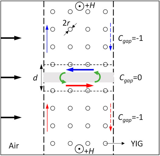
FIGURE 1. Schematics of the GPC waveguide involving strongly coupling of two counter-propagating TPSs. The plane wave is incident along the horizontal direction from the left port (marked as black arrows), the blue and red arrows represent the transport direction of topological one-way edge states, and the green arrows indicate the strongly coupling of two counter-propagating topological one-way edge states.
When GPC waveguide is applied with external magnetic field along the + z direction, the time reversal symmetry of upper and lower half GPCs is broken by opening a non-trivial bandgap so that the two half GPCs possess a non-zero gap Chern number (i.e., Cgap = −1). Besides, the gap Chern number of the air is Cgap = 0. Thus, the upper and lower half GPCs both support topological one-way edge states propagating clockwise, and the one-way edge state transport directions of the upper and lower half GPCs are marked as the blue and red arrows, respectively, as shown in Figure 1. We calculate the projected band structure of the upper and lower half GPCs, respectively, as shown in Figure 2A,B. The waveguide width of them is d10 = 71.75 mm. For the upper half and lower half GPCs, there exist the leftward and rightward propagating topological one-way edge states in the bandgap, respectively. Then, we construct a waveguide by moving the upper half and lower half GPCs close to each other head by head. As the waveguide width decreases, we find that in the middle part of the Brillouin zone (−0.6 < kx < 0.6), the shape of dispersion curve (colored in red) gradually changes from concave to flat and then to convex, as shown in Figure 2C–I, showing that these two counter-propagating topological one-way edge states will be coupled with each other. Especially, for the broad waveguides with d11 = 71.75 mm, d12 = 68.25 mm, d13 = 64.75 mm, and d14 = 61.25 mm, their bands are convex in profile, as shown in Figure 2C–F. While for narrow waveguides with d16 = 54.25 mm and d17 = 50.75 mm, its band has a concave profile, as plotted in Figure 2H,I. Right at d15 = 57.75 mm, the band exhibits a flat profile (i.e., slow light band), as shown in Figure 2G. In this case, the two counter-propagating topological one-way edge states will be strongly coupled with each other, which causes nearly complete exchange and transfer of energy flow between the rightward and leftward propagating topological one-way edge states and finally results in a very low velocity of the wave transport.
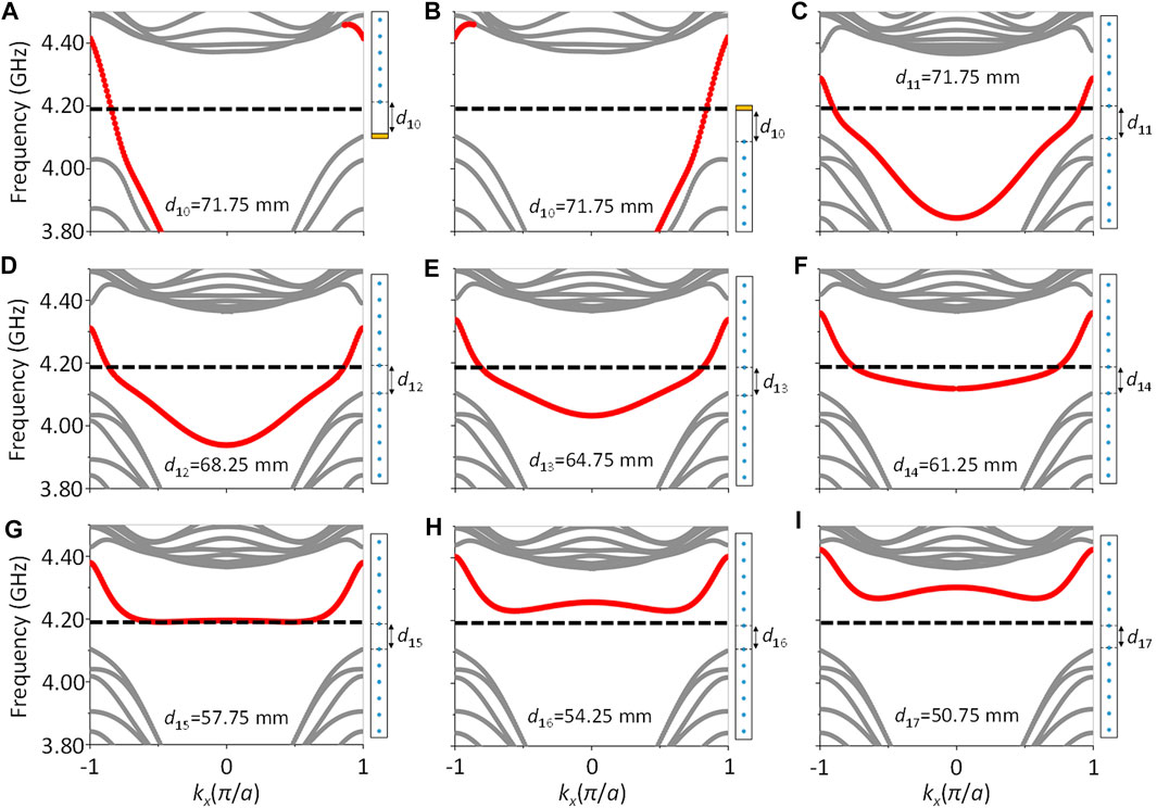
FIGURE 2. Projected band structure. (A) Upper half GPC with a waveguide width d10 = 71.75 mm. (B) Lower half GPC with d10 = 71.75 mm. The yellow layers in (a) and (b) are the perfect electric conductors. (c–i) GPC waveguide composed of two GPCs with different waveguide widths: (C) d11 = 71.75 mm, (D) d12 = 68.25 mm, (E) d13 = 64.75 mm, (F) d14 = 61.25 mm, (G) d15 = 57.75 mm, (H) d16 = 54.25 mm, and (I) d17 = 50.75 mm. The frequency marked by the black dotted line is 4.1902 GHz.
To vividly show the coupling process between the two counter-propagating topological one-way edge states as the waveguide width decreases, we simulate the transport phenomena of a plane wave incident from the left port at a frequency of 4.1902 GHz in different waveguide widths, as shown in Figure 3. When d11 = 71.75 mm, the electric field distribution is asymmetrical along the center of the waveguide channel, and the electric field of the lower edge is larger than that of the upper edge. As the waveguide width decreases from d11 = 71.75 mm to d14 = 61.25 mm, the electric field intensity of the lower edge gradually decreases, while that of the upper edge gradually increases, which means that more and more electric fields propagating rightward along the lower edge are coupled by the upper edge and propagates leftward, as shown in Figure 3A–D. Right at d15 = 57.75 mm, the electric fields of the lower and upper edges are strongly coupled with each other, and the rightward-propagating electric field is almost equal to the counter-propagating part, which causes nearly complete exchange and transfer of energy flow between the rightward and leftward topological one-way edge states, induces a counterclockwise energy loop in the waveguide channel (see Figure 1), and finally results in a very low group velocity of the wave transport (i.e., exhibiting a quite flat band in the middle part of the Brillouin zone in Figure 2G), and the electric field in the waveguide channel is greatly enhanced, as shown in Figure 3E. When the waveguide width continues to decrease to d16 = 54.25 mm, as shown in Figure 3F, the incident plane wave at a frequency of 4.1902 GHz cannot excite any waveguide mode, and this also can be seen in Figure 2H. Therefore, the strong coupling of the two counter-propagating topological one-way edge states can be controllably regulated by changing the structural parameters. Besides, it should be emphasized that these slow light states are not topologically protected due to the Chern number of the total GPC waveguide being zero, but the topology still plays a critical role because these slow light states are originated from the strong coupling of two counter-propagating topological one-way edge states. Besides, due to the existence of the one-way edge state in the left edge of lower half GPC, the external EM wave can be non-reciprocally coupled to the waveguide channel, although the incident position of the EM wave is far away from the waveguide channel, which will be discussed later.
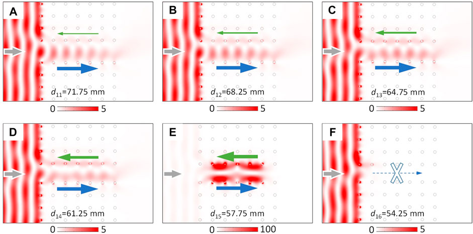
FIGURE 3. Electric field distribution of the waveguide channel with different waveguide widths. (A) d11 = 71.75 mm, (B) d12 = 68.25 mm, (C) d13 = 64.75 mm, (D) d14 = 61.25 mm, (E) d15 = 57.75 mm, and (F) d16 = 54.25 mm. The blue and green arrows indicate the transport direction of the topological one-way edge states at the lower and upper edges, respectively. The thickness of the arrow represents the relative intensity of the electric field between the lower and upper edges.
Next, we perform the numerical calculations of band diagrams for four GPC waveguide segments with different radii r and waveguide widths d biased by a uniform external magnetic field of H0 = 1600 G, as shown in Figure 4. They are WG. 1 (r1 = 4.35 mm, d1 = 57.75 mm), WG. 2 (r2 = 4.40 mm, d2 = 58.10 mm), WG. 3 (r3 = 4.45 mm, d3 = 58.55 mm), and WG. 4 (r4 = 4.45 mm, d4 = 58.90 mm). The calculated result of WG. 1 is shown in Figure 4A. It should be noted that the waveguide width between two GPCs should be appropriately selected so that the two counter-propagating topological one-way edge states can strongly couple with each other and result in a quite flat band in the middle part of the Brillouin zone. One can see that an exotic flat band (colored in red) exists in the middle part of the Brillouin zone, which means that the group velocities of guided modes at a frequency of f1 = 4.1902 GHz belonging to the flat band are extremely low. For WG. 2 in Figure 4B, the shape of the flat band (colored in blue) is almost unchanged compared with the flat band in Figure 4A, but the frequency of slow light state decreases to f2 = 4.1614 GHz. When the radius and waveguide width of the GPC waveguide continue to increase to r3 = 4.45 mm and d3 = 58.55 mm, respectively (i.e., WG. 3), the frequency of the slow light state decreases to f3 = 4.1314 GHz, as shown in the green flat band of Figure 4C. As can be seen from the band structure of WG. 4 (r4 = 4.45 mm, d4 = 58.90 mm), as shown in Figure 4D, there exists a purple flat band, and the slow light state localizes at f4 = 4.1032 GHz. Thus, under a uniform external magnetic field, by increasing the radius from r1 to r4 and the waveguide width from d1 to d4, respectively, the frequency of slow the light state can move down from 4.1902 to 4.1032 GHz.
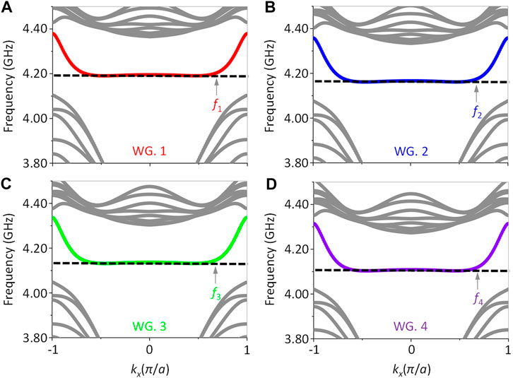
FIGURE 4. Projected band structure of the GPC waveguide segment. (A) WG. 1: r1 = 4.35 mm, d1 = 57.75 mm, and f1 = 4.1902 GHz. (B) WG. 2: r2 = 4.40 mm, d2 = 58.10 mm, and f2 = 4.1614 GHz. (C) WG. 3: r3 = 4.45 mm, d3 = 58.55 mm, and f3 = 4.1314 GHz. (D) WG. 4: r4 = 4.45 mm, d4 = 58.90 mm, and f4 = 4.1032 GHz.
We proceed to construct an air–GPC waveguide–air model to demonstrate the transport behaviors of the slow light state belonging to the flat band in the frequency domain. The plane wave is incident in the horizontal direction from the left port, and the other three boundaries are set as the scattering boundary conditions that can greatly reduce the reflection. The simulated result of air–WG. 1–air is plotted in Figure 5A, and the operating frequency is f1 = 4.1902 GHz. We can see that the electric field is mainly concentrated on the waveguide channel, and only a very small amount of electric field is distributed in the air on the left part, while there is no electric field distributing in the air on the right part. This result shows that an EM wave incident from the left port can be effectively coupled to the waveguide channel, and its group velocity will be greatly slowed down and trapped at the waveguide channel as the EM wave propagates via a counterclockwise energy flux closed-loop manner that originates from the strong coupling of the two counter-propagating topological one-way edge states. Similarly, as shown in Figure 5B–D, the plane waves at f2 = 4.1614 GHz, f3 = 4.1314 GHz, and f4 = 4.1032 GHz incident from the left port will be slowed down and trapped at the WG. 2, WG. 3, and WG. 4, respectively.
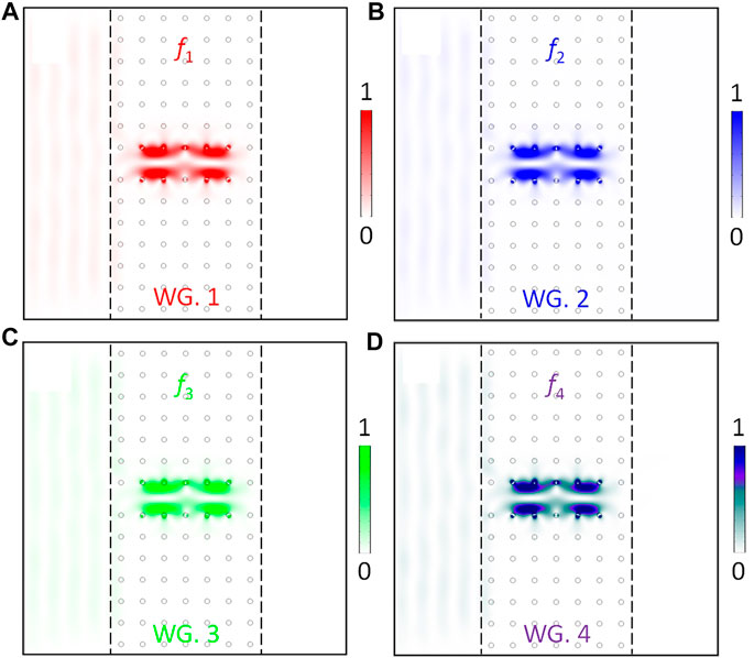
FIGURE 5. Normalized electric field distribution in four types of slow light waveguide segments. (A) WG. 1: f1 = 4.1902 GHz. (B) WG. 2: f2 = 4.1614 GHz. (C) WG. 3: f3 = 4.1314 GHz. (D) WG. 4: f4 = 4.1032 GHz. The electric field diagrams of frequencies f1, f2, f3, and f4 are marked in red, blue, green, and purple, respectively.
To further verify the slow light trapping characteristics of the waveguide channel, we calculate the electric field intensity in four types of the waveguide segment at different frequencies, as shown in Figure 6. These electric field intensity spectra are obtained by integrating and normalizing the electric field of the entire waveguide channel area excited by the plane waves from the left port at a frequency range from 4.185 to 4.195 GHz. For WG. 1, as shown in Figure 6A, the frequency range of the EM wave is from 4.185 up to 4.195 GHz. There only exists a high peak at f1 = 4.1902 GHz, which means that the electric field is strongly localized at the waveguide channel, being completely consistent with the simulated result in Figure 5A. Besides, as the frequency increases from 4.1850 to 4.1902 GHz, the intensity of the electric field first maintains a value close to 0 and then increases sharply to the maximum value of 1. This is because the EM wave at a frequency lower than 4.1902 GHz cannot excite any guided modes in the waveguide channel; consequently, the incident EM wave will be totally reflected at the junction of air and waveguide. However, when the frequency is higher than 4.1902 GHz, the guided mode with a high group velocity will be excited. Thus, the electric field can have a great probability to propagate through the waveguide channel and transmit into the air, so that only a part of electric field exists in the waveguide channel. These results are consistent with the band structure analysis in Figure 4A. Likewise, Figure 6B–D also shows the relationship of electric field intensity and frequency of WG. 2, WG. 3, and WG. 4, respectively. Obviously, the shape of intensity curves of them are similar to that of Figure 6A, but they possess the high peak at the frequencies of f2 = 4.1614 GHz, f3 = 4.1314 GHz, and f4 = 4.1032 GHz, respectively, which are completely consistent with the calculated results of Figures 4, 5.
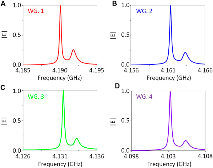
FIGURE 6. Normalized electric field intensity in the four types of waveguide segments at different frequencies. (A) WG. 1. (B) WG. 2. (C) WG. 3. (D) WG. 4. The intensity curves of WG. 1, WG. 2, WG. 3, and WG. 4 are marked in red, blue, green, and purple, respectively.
We have mentioned above that the gap Chern number of the slow light waveguide segment is 0, meaning that the waveguide segment is trivial and not topologically protected, but it still retains the topological transport characteristics, especially the topological one-way edge states existing on the left and right edges, as shown in Figure 1. We consider the left edge of the slow light waveguide segment and find that the upper and lower edges both support the topological one-way edge state propagating upward. We first set a plane wave with a width of 5a propagating from the left port along horizontal direction. When the EM wave at f1 = 4.1902 GHz meets the left upper edge of WG. 1, the one-way edge state propagating upward will be excited so that the electric field of reflection light loses symmetry about the direction of an incident plane wave and almost no guided mode is excited in the waveguide channel, as shown in Figure 7A.
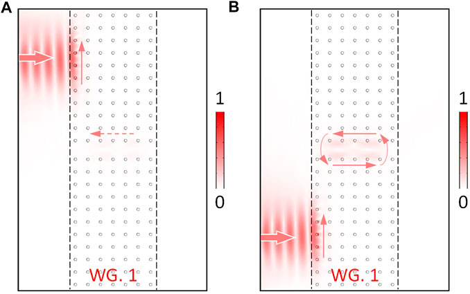
FIGURE 7. Remotely and non-reciprocally exciting slow light state. The rough arrows represent the transmission direction of the incident plane wave, and the thin arrows indicate the propagating direction of topological one-way edge states.
On the other hand, when the plane wave is incident from the left lower port to irradiate the left lower edge of WG. 1, as shown in Figure 7B, the asymmetrical reflection still occurs because the left lower edge supports the one-way edge state transporting upward. Consequently, the electric field distribution of reflection of Figure 7B is almost the same as that of Figure 7A. However, it is intriguing that the slow light state in the waveguide channel can be remotely excited by the left lower plane wave; this is because the EM wave can flow into the waveguide channel through the one-way channel at the left lower edge. This phenomenon has never been mentioned in previous studies. Therefore, the existence of the one-way edge state in the left edge of the lower half GPC can support the external EM waves can be non-reciprocally coupled to the SLRT waveguide channel, although the incident position of the EM wave is far away from the waveguide channel. These results can help us further to realize an SLRT waveguide which can be remotely and non-reciprocally excited by external EM waves.
We proceed to construct a hybrid GPC waveguide by splicing four GPC waveguide segments together to form a line defect channel to demonstrate the SLRT phenomenon in frequency and time domains. As shown in Figure 8, WG. 4, WG. 3, WG. 2, and WG. 1 are placed one by one from left to right. This is because the frequency of the slow light state of the latter waveguide must be able to excite the guided mode of the former waveguide so that the EM wave can pass through the former waveguide and is slowed down and trapped at the concerned waveguide, that is, f4<f3<f2<f1. When EM waves of f4, f3, f2, and f1 are incident at the hybrid waveguide, they are slowed down and trapped at their corresponding locations, as shown in Figure 8A, and finally form an SLRT phenomenon in the frequency domain. More importantly, this SLRT possesses a high spatial precision where there are almost no cross talk and overlap between the electric fields of different frequencies (see Figure 8B), which is very different from the rainbow trapping phenomena, as mentioned in previous studies (Gan et al., 2009; Jiang and Atwater, 2011; Lu et al., 2021). This feature is attributed to the huge difference of group velocity between the former waveguide and slow light waveguide at the frequency of the slow light state so that the electric field can be almost completely localized in the concerned slow light waveguide channel.

FIGURE 8. Slow light rainbow trapping in frequency domain. (A) f4 = 4.1032 GHz, f3 = 4.1314 GHz, f2 = 4.1614 GHz, and f1 = 4.1902 GHz. (B) Normalized electric field intensities along the lower boundary for different frequencies. The interfaces of adjacent waveguide segments are marked as the black dotted lines.
We further demonstrate the SLRT phenomenon in a time domain. A Gaussian wave packet centered at f0 = 4.15 GHz is incident from the left port, and the full width at half-maxima of the pulse is 0.1 GHz (from 4.10 to 4.20 GHz). Figure 9A–E shows the electric field distributions along the lower boundary of the waveguide channel at t1 = 10.0 ns, t2 = 42.5 ns, t3 = 75.0 ns, t4 = 107.5 ns, and t5 = 140.0 ns, respectively. Especially, at t1 = 10.0 ns, most of EM waves arrive in WG. 4 and WG. 3, while only a little energy reaches WG. 2 and WG. 1, as shown in Figure 9A. At t2 = 42.5 ns, the Gaussian pulse should have gone through the whole structure; however, there still exists a relatively strong electric field distribution inside each waveguide segment, as shown in Figure 9B. As time elapses, at t3 = 75.0 ns, the intensity of trapped EM waves in WGs. 4, 3, 2, and 1 becomes weaker due to the leakage of energy fluxes on both sides of the waveguide channel, as shown in Figure 9C. However, as time continues to pass, the rate of energy loss is significantly reduced. The calculated results at t4 = 107.5 ns and t5 = 140.0 ns are plotted in Figures 9D–E, respectively, where we can see that there only a few EM waves leak out of the waveguide channel. We proceed to calculate the frequency spectrum at x1 = 4a (WG. 4), x2 = 11a (WG. 3), x3 = 18a (WG. 2), and x4 = 25a (WG. 1) between 100.0 and 140.0 ns, as shown in Figure 9F. The corresponding peak frequencies are at fa = 4.1041 GHz, fb = 4.1313 GHz, fc = 4.1568 GHz, and fd = 4.1912 GHz, which agrees well with the frequency domain simulations (i.e., fa˜ f4, fb˜ f3, fc˜ f2, and fd˜ f1). Therefore, all these results have shown that the different frequency components of a Gaussian wave packet indeed can be separated and stored at different positions of the waveguide for a long temporal duration to form SLRT.
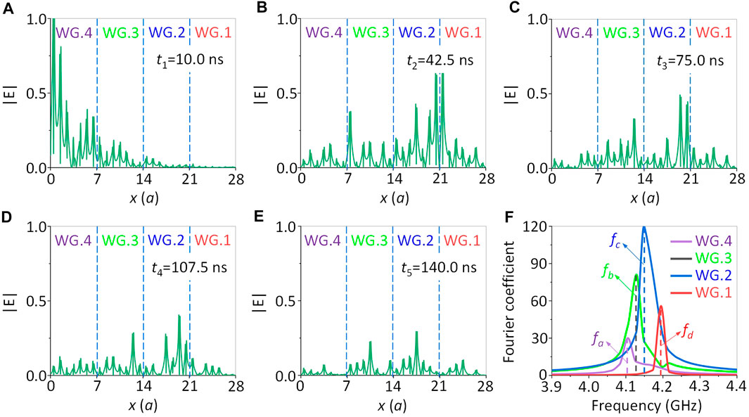
FIGURE 9. Slow light rainbow trapping in time domain. Electric field amplitudes of the wave packet along the lower boundary at different times: (A) t1 = 10.0 ns, (B) t2 = 42.5 ns, (C) t3 = 75.0 ns, (D) t3 = 107.5 ns, (E) t3 = 140.0 ns, and (F) Fourier transformation spectrum at x1 = 4a (WG. 4), x2 = 11a (WG. 3), x3 = 18a (WG. 2), and x4 = 25a (WG. 1) along the lower boundary of the waveguide channel.
The intensity of the external magnetic field is one of the most important tunable freedom of GPC systems, which can be used to regulate the transport behaviors of an EM wave. Here, we display a synthetic diagram of the intensity of an electric field in WG. 1 under different H0. The intensity of H0 continuously and linearly increases from 1,000 to 1800 G with ΔH0 = 100 G. As H0 increases, the frequency of the slow light state blue shifts from 3.5701 to 4.3121 GHz, as shown in Figure 10. On the other hand, the magnitude of the frequency blue shift of the slow light state decreases; this is because H0 is gradually approaching the saturation magnetization. It can thus be seen clearly that the slow light states originating from the strongly coupling of two counter-propagating topological one-way edge states can be easily achieved and conveniently modulated by changing the geometrical parameters of the structure and intensity of the external magnetic field. These features are very beneficial to create extremely broadband-tunable slow light states and the SLRT phenomenon and can provide a powerful path to solve the contradiction between slow light and broad bandwidths.
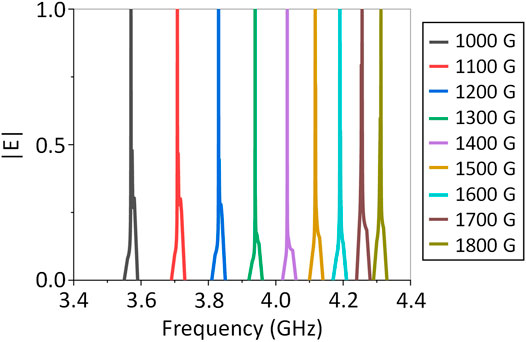
FIGURE 10. Magnetically tunable broadband slow light. The frequencies of slow light states are 3.5701, 3.7078, 3.8301, 3.9385, 4.0340, 4.1171, 4.1902, 4.2562, and 4.3121 GHz under the external magnetic field of 1,000, 1,100, 1,200, 1,300, 1,400, 1,500, 1,600, 1700, and 1800 G, respectively.
In summary, we have proposed a hybrid GPC waveguide composed of four segments of GPC waveguides possessing different cylinder radii and waveguide widths but biased by a uniform external magnetic field to demonstrate the SLRT of EM waves. We have demonstrated that in frequency and time domains, EM waves of different frequencies can be slowed down and trapped at their corresponding locations almost free from any cross talk and overlap. More intriguingly, we have found that attributed to the presence of one-way transport channel at the left edge, external EM waves can be remotely and non-reciprocally coupled to the slow light waveguide channel. Moreover, the frequency range of slow light states can also be easily and conveniently tuned by regulating the intensity of the external magnetic field to obtain the extremely broadband slow light states. All these topological features are very beneficial to solve the contradiction between slow light and broad bandwidths. Our results may provide a great potential for designing novel photonic devices with high performance, such as an optical buffer, optical switch, and optical filter.
It should be emphasized that the similar topological rainbow phenomena have been studied in previous studies (Chen et al., 2019b; Zhang et al., 2021), but our ideas and studies are completely different from them. On the one hand, in ref. Chen et al. (2019b), the gradient magnetic field is required, which is difficult to be obtained in the actual experimental configuration. While in this study, we use a uniform external magnetic field to form a tunable SLRT with a broadband. Obviously, the uniform external magnetic field is easier to implement in experiments than the gradient magnetic field. On the other hand, in ref. Zhang et al. (2021), the authors realized a rainbow based on graded dielectric photonic crystals, which are constructed by changing the degree of lattice contraction and expansion, so its physical mechanism of rainbow is completely distinguished from our study. Besides, this rainbow waveguide is composed of a dielectric material; thus, once its structure is fabricated, its properties cannot be adjusted, which greatly limits the application of rainbow waveguides. However, the rainbow in our study can be tuned by an external magnetic field. This feature is very beneficial to create extremely broadband-tunable slow light states and a rainbow phenomenon and can provide a powerful path to solve the contradiction between slow light and broad bandwidths. Besides, the distribution length of each footprint in the slow light rainbow is about 2.7λ; it will be very valuable for the realization of a more compact rainbow waveguide if we can explore a novel physical mechanism that enables the EM wave to be captured in a small space, even a point.
The raw data supporting the conclusions of this article will be made available by the authors, without undue reservation.
All authors contributed extensively to this work. JC, WL, and Z-YL designed the structure. JC, QQ, and CP performed the simulation. JC, WL, and Z-YL provided major theoretical analysis. JC, QQ, and CP drew the figures. JC and Z-YL wrote the manuscript. Z-YL supervised the project. All authors participated in discussions and reviewed the manuscript.
National Natural Science Foundation of China (12074127, 11974119), Science and Technology Project of Guangdong (2020B010190001), Science and Technology Program of Guangzhou (201904010105), Guangdong Innovative and Entrepreneurial Research Team Program (2016ZT06C594), Fundamental Research Funds for the Central Universities (2019ZD50), National Key R&D Program of China (2018YFA 0306200).
The authors declare that the research was conducted in the absence of any commercial or financial relationships that could be construed as a potential conflict of interest.
All claims expressed in this article are solely those of the authors and do not necessarily represent those of their affiliated organizations or those of the publisher, the editors, and the reviewers. Any product that may be evaluated in this article, or claim that may be made by its manufacturer, is not guaranteed or endorsed by the publisher.
The authors are grateful for the financial support from the National Natural Science Foundation of China (12074127, 11974119), Science and Technology Project of Guangdong (2020B010190001), Science and Technology Program of Guangzhou (201904010105), Guangdong Innovative and Entrepreneurial Research Team Program (2016ZT06C594), Fundamental Research Funds for the Central Universities (2019ZD50), National Key R&D Program of China (2018YFA 0306200).
Bahari, B., Ndao, A., Vallini, F., El Amili, A., Fainman, Y., and Kanté, B. (2017). Nonreciprocal Lasing in Topological Cavities of Arbitrary Geometries. Science 358 (6363), 636–640. doi:10.1126/science.aao4551
Bandres, M. A., Wittek, S., Harari, G., Parto, M., Ren, J., Segev, M., et al. (2018). Topological Insulator Laser: Experiments. Science 359 (6381), eaar4005. doi:10.1126/science.aar4005
Chen, J., Liang, W., and Li, Z. Y. (2021). Progress of Topological Photonic State in Magneto-Optical Photonic crystal. Acta Optic. Sin. 41 (8), 0823005. doi:10.3788/aos202141.0823015
Chen, J., Liang, W., and Li, Z. Y. (2019). Strong Coupling of Topological Edge States Enabling Group-Dispersionless Slow Light in Magneto-Optical Photonic Crystals. Phys. Rev. B 99 (1), 014103. doi:10.1103/physrevb.99.014103
Chen, J., Liang, W., and Li, Z. Y. (2019). Switchable Slow Light Rainbow Trapping and Releasing in Strongly Coupling Topological Photonic Systems. Photon. Res 19 (9), 091075. doi:10.1364/prj.7.001075
Chen, J., Liang, W., and Li, Z.-Y. (2020). Broadband Dispersionless Topological Slow Light. Opt. Lett. 45 (18), 4964–4967. doi:10.1364/ol.401650
Chen, X. D., Zhao, F., Chen, M., and Dong, J. W. (2017). Valley-contrasting Physics in All-Dielectric Photonic Crystals: Orbital Angular Momentum and Topological Propagation. Phys. Rev. B 96 (2), 020202. doi:10.1103/physrevb.96.020202
Chen, X.-D., Deng, W.-M., Zhao, F.-L., and Dong, J.-W. (2018). Accidental Double Dirac Cones and Robust Edge States in Topological Anisotropic Photonic Crystals. Laser Photon. Rev. 12 (11), 1800073. doi:10.1002/lpor.201800073
Chen, Y., He, X.-T., Cheng, Y.-J., Qiu, H.-Y., Feng, L.-T., Zhang, M., et al. (2021). Topologically Protected valley-dependent Quantum Photonic Circuits. Phys. Rev. Lett. 126 (23), 230503. doi:10.1103/physrevlett.126.230503
Dobrykh, D. A., Yulin, A. V., Slobozhanyuk, A. P., Poddubny, A. N., and Kivshar, Y. S. (2018). Nonlinear Control of Electromagnetic Topological Edge States. Phys. Rev. Lett. 121 (16), 163901. doi:10.1103/physrevlett.121.163901
Dong, J.-W., Chen, X.-D., Zhu, H., Wang, Y., and Zhang, X. (2017). Valley Photonic Crystals for Control of Spin and Topology. Nat. Mater 16 (3), 298–302. doi:10.1038/nmat4807
Fu, J.-X., Liu, R.-J., and Li, Z.-Y. (2010). Robust One-Way Modes in Gyromagnetic Photonic crystal Waveguides with Different Interfaces. Appl. Phys. Lett. 97 (4), 041112. doi:10.1063/1.3470873
Gan, Q., Ding, Y. J., and Bartoli, F. J. (2009). “Rainbow” Trapping and Releasing at Telecommunication Wavelengths. Phys. Rev. Lett. 102 (5), 056801. doi:10.1103/PhysRevLett.102.056801
Gao, W., Lawrence, M., Yang, B., Liu, F., Fang, F., Béri, B., et al. (2015). Topological Photonic Phase in Chiral Hyperbolic Metamaterials. Phys. Rev. Lett. 114 (3), 037402. doi:10.1103/PhysRevLett.114.037402
Harari, G., Bandres, M. A., Lumer, Y., Rechtsman, M. C., Chong, Y. D., Khajavikhan, M., et al. (2018). Topological Insulator Laser: Theory. Science 359 (6381), eaar4003. doi:10.1126/science.aar4003
He, X.-T., Liang, E.-T., Yuan, J.-J., Qiu, H.-Y., Chen, X.-D., Zhao, F.-L., et al. (2019). A Silicon-On-Insulator Slab for Topological valley Transport. Nat. Commun. 10 (1), 872. doi:10.1038/s41467-019-08881-z
Jia, H., Zhang, R., Gao, W., Guo, Q., Yang, B., Hu, J., et al. (2019). Observation of Chiral Zero Mode in Inhomogeneous Three-Dimensional Weyl Metamaterials. Science 363 (6423), 148–151. doi:10.1126/science.aau7707
Jiang, M. S., and Atwater, H. (2011). Plasmonic Rainbow Trapping Structures for Light Localization and Spectrum Splitting. Phys. Rev. Lett. 107 (20), 207401. doi:10.1103/PhysRevLett.107.207401
Khanikaev, A. B., Hossein Mousavi, S., Tse, W.-K., Kargarian, M., MacDonald, A. H., and Shvets, G. (2013). Photonic Topological Insulators. Nat. Mater 12 (3), 233–239. doi:10.1038/nmat3520
Khanikaev, A. B., and Shvets, G. (2017). Two-dimensional Topological Photonics. Nat. Photon 11 (12), 763–773. doi:10.1038/s41566-017-0048-5
Kim, M., Jacob, Z., and Rho, J. (2020). Recent Advances in 2D, 3D and Higher-Order Topological Photonics. Light Sci. Appl. 9 (1), 130. doi:10.1038/s41377-020-0331-y
Kruk, S., Poddubny, A., Smirnova, D., Wang, L., Slobozhanyuk, A., Shorokhov, A., et al. (2018). Nonlinear Light Generation in Topological Nanostructures. Nat. Nanotech 14 (2), 126–130. doi:10.1038/s41565-018-0324-7
Kruk, S., Slobozhanyuk, A., Denkova, D., Poddubny, A., Kravchenko, I., Miroshnichenko, A., et al. (2017). Edge States and Topological Phase Transitions in Chains of Dielectric Nanoparticles. Small 13 (11), 1603190. doi:10.1002/smll.201603190
Leykam, D., and Chong, Y. D. (2016). Edge Solitons in Nonlinear-Photonic Topological Insulators. Phys. Rev. Lett. 117 (14), 143901. doi:10.1103/physrevlett.117.143901
Lin, H., and Lu, L. (2020). Dirac-vortex Topological Photonic crystal Fibre. Light Sci. Appl. 9 (1), 202–207. doi:10.1038/s41377-020-00432-2
Lu, C., Wang, C., Xiao, M., Zhang, Z. Q., and Chan, C. T. (2021). Topological Rainbow Concentrator Based on Synthetic Dimension. Phys. Rev. Lett. 126 (11), 113902. doi:10.1103/physrevlett.126.113902
Lu, L., Gao, H., and Wang, Z. (2018). Topological One-Way Fiber of Second Chern Number. Nat. Commun. 9 (1), 5384. doi:10.1038/s41467-018-07817-3
Lu, L., Joannopoulos, J. D., and Soljačić, M. (2014). Topological Photonics. Nat. Photon 8 (11), 821–829. doi:10.1038/nphoton.2014.248
Lu, L., Joannopoulos, J. D., and Soljačić, M. (2016). Topological States in Photonic Systems. Nat. Phys 12 (7), 626–629. doi:10.1038/nphys3796
Ozawa, T., Price, H. M., Amo, A., Goldman, N., Hafezi, M., Lu, L., et al. (2019). Topological Photonics. Rev. Mod. Phys. 91 (1), 015006. doi:10.1103/revmodphys.91.015006
Poo, Y., Wu, R. X., Lin, Z., Yang, Y., and Chan, C. T. (2011). Experimental Realization of Self-Guiding Unidirectional Electromagnetic Edge States. Phys. Rev. Lett. 106 (9), 093903. doi:10.1103/PhysRevLett.106.093903
Shao, Z.-K., Chen, H.-Z., Wang, S., Mao, X.-R., Yang, Z.-Q., Wang, S.-L., et al. (2020). A High-Performance Topological Bulk Laser Based on Band-Inversion-Induced Reflection. Nat. Nanotechnol. 15 (1), 67–72. doi:10.1038/s41565-019-0584-x
Shi, F. L., Cao, Y., Chen, X. D., Liu, J. W., Chen, W., Chen, M., et al. (2021). Distortionless Pulse Transmission in valley Photonic crystal Slab Waveguide. Phys. Rev. Appl. 15 (2), 024002. doi:10.1103/physrevapplied.15.024002
Smirnova, D., Kruk, S., Leykam, D., Melik-Gaykazyan, E., Choi, D.-Y., and Kivshar, Y. (2019). Third-harmonic Generation in Photonic Topological Metasurfaces. Phys. Rev. Lett. 123 (10), 103901. doi:10.1103/physrevlett.123.103901
Smirnova, D., Leykam, D., Chong, Y., and Kivshar, Y. (2020). Nonlinear Topological Photonics. Appl. Phys. Rev. 7 (2), 021306. doi:10.1063/1.5142397
Tang, G. J., Chen, X. D., and Dong, J. W. (2019). Valley Photonic Crystals and Topological Propagation of Light. Physics 48 (6), 376–384. doi:10.7693/wl20190604
Wang, H., Gupta, S. K., Xie, B., and Lu, M. (2020). Topological Photonic Crystals: a Review. Front. Optoelectron. 13 (1), 50–72. doi:10.1007/s12200-019-0949-7
Wang, Z., Chong, Y. D., Joannopoulos, J. D., and Soljacić, M. (2008). Reflection-free One-Way Edge Modes in a Gyromagnetic Photonic crystal. Phys. Rev. Lett. 100 (1), 013905. doi:10.1103/PhysRevLett.100.013905
Wang, Z., Chong, Y., Joannopoulos, J. D., and Soljačić, M. (2009). Observation of Unidirectional Backscattering-Immune Topological Electromagnetic States. Nature 461 (7265), 772–775. doi:10.1038/nature08293
Xie, B.-Y., Wang, H.-F., Zhu, X.-Y., Lu, M.-H., Wang, Z. D., and Chen, Y.-F. (2018). Photonics Meets Topology. Opt. Express 26 (19), 24531–24550. doi:10.1364/oe.26.024531
Yang, B., Guo, Q., Tremain, B., Liu, R., Barr, L. E., Yan, Q., et al. (2018). Ideal Weyl Points and Helicoid Surface States in Artificial Photonic crystal Structures. Science 359 (6379), 1013–1016. doi:10.1126/science.aaq1221
Yang, Y., Gao, Z., Xue, H., Zhang, L., He, M., Yang, Z., et al. (2019). Realization of a Three-Dimensional Photonic Topological Insulator. Nature 565 (7741), 622–626. doi:10.1038/s41586-018-0829-0
Yang, Y., Poo, Y., Wu, R.-x., Gu, Y., and Chen, P. (2013). Experimental Demonstration of One-Way Slow Wave in Waveguide Involving Gyromagnetic Photonic Crystals. Appl. Phys. Lett. 102 (23), 231113. doi:10.1063/1.4809956
Zangeneh-Nejad, F., and Fleury, R. (2019). Nonlinear Second-Order Topological Insulators. Phys. Rev. Lett. 123 (5), 053902. doi:10.1103/PhysRevLett.123.053902
Zeng, Y., Chattopadhyay, U., Zhu, B., Qiang, B., Li, J., Jin, Y., et al. (2020). Electrically Pumped Topological Laser with valley Edge Modes. Nature 578 (7794), 246–250. doi:10.1038/s41586-020-1981-x
Keywords: slow light rainbow trapping, strongly coupling of topological photonic states, remotely and non-reciprocally exciting, tunable broadband slow light, gyromagnetic photonic crystal
Citation: Chen J, Qin Q, Peng C, Liang W and Li Z-Y (2021) Slow Light Rainbow Trapping in a Uniformly Magnetized Gyromagnetic Photonic Crystal Waveguide. Front. Mater. 8:728991. doi: 10.3389/fmats.2021.728991
Received: 22 June 2021; Accepted: 12 August 2021;
Published: 29 September 2021.
Edited by:
Xiao-Dong Chen, Sun Yat-Sen University, ChinaCopyright © 2021 Chen, Qin, Peng, Liang and Li. This is an open-access article distributed under the terms of the Creative Commons Attribution License (CC BY). The use, distribution or reproduction in other forums is permitted, provided the original author(s) and the copyright owner(s) are credited and that the original publication in this journal is cited, in accordance with accepted academic practice. No use, distribution or reproduction is permitted which does not comply with these terms.
*Correspondence: Zhi-Yuan Li, cGh6eWxpQHNjdXQuZWR1LmNu
Disclaimer: All claims expressed in this article are solely those of the authors and do not necessarily represent those of their affiliated organizations, or those of the publisher, the editors and the reviewers. Any product that may be evaluated in this article or claim that may be made by its manufacturer is not guaranteed or endorsed by the publisher.
Research integrity at Frontiers
Learn more about the work of our research integrity team to safeguard the quality of each article we publish.