 Mozaffar Mokhtari
 Edward Archer
 Noel Bloomfield2
94% of researchers rate our articles as excellent or good
Learn more about the work of our research integrity team to safeguard the quality of each article we publish.
Find out more
ORIGINAL RESEARCH article
Front. Mater. , 15 September 2021
Sec. Polymeric and Composite Materials
Volume 8 - 2021 | https://doi.org/10.3389/fmats.2021.724958
This article is part of the Research Topic Carbon Nanomaterial Filled Polymer Composites for Functional Applications: Processing, Structure, and Property Relationship View all 13 articles
In this work, antistatic, high-performance composites of poly (ether ether ketone) (PEEK) and concentrations of 0.5–7 vol% expanded graphite (EG) were fabricated via twin-screw extrusion and injection moulding at mould temperatures of 200°C. The morphological, electrical, rheological, thermal, mechanical, and wear properties of the composites were investigated. Scanning electron microscope (SEM) images indicate that distribution and dispersion of EG platelets in the PEEK matrix are enhanced at higher EG loadings. The electrical conductivity of the composites with 5 vol% of EG exhibits a sharp rise in the electrical conductivity range of antistatic materials because of the formation of conductive paths. The formation of a three-dimensional EG network led to a rapid increase in the storage modulus of the melt of the 2 vol% of EG-loaded composite at a frequency of 0.1 rad/s and temperature of 370°C. The neat PEEK and composites containing 0.5–5 vol% EG indicated a cold-crystallisation peak in the first heating scan of a non-isothermal differential scan calorimetry (DSC) test and their crystallinity degrees changed slightly. However, after removing their thermal and stress histories, the EG platelets promoted nucleation and increased the PEEK crystallinity remarkably, indicating that annealing of the PEEK composites can improve their mechanical performance. The neat PEEK exhibits the standard tensile and flexural stress-strain behaviour of thermoplastics, and the composites exhibit elastic behaviour initially followed by a weak plastic deformation before fracture. The addition of 5 vol% of EG to PEEK increased the tensile and flexural modulus from 3.84 and 3.55 GPa to 4.15 and 4.40 GPa, decreased the strength from 96.73 and 156.41 MPa to 62 and 118.19 MPa, and the elongation at break from 27.09 and 12.9% to 4 and 4.6%, respectively. The wear resistance of the composite containing 3 vol% EG was enhanced by 37% compared with the neat PEEK.
Poly (ether ether ketone) (PEEK) has a variety of promising properties such as high chemical resistance, outstanding mechanical properties, and good thermal and dimensional stabilities due to its aromatic and semicrystalline backbone. These properties and the easier processing of PEEK as compared with metals, biocompatibility, and transparency to radiation have increased interest in its usage in industries such as biomedical, aerospace, and automotive. Also, the improvement of the electrical conductivity and wear resistance of PEEK has extended its applications noticeably (Pei et al., 2019; Puértolas et al., 2019; Zhang et al., 2019; Schroeder et al., 2020). For example, electrically conductive PEEK materials have been utilised to manufacture reflectors for parabolic space antenna in satellites, cryogenic storage tanks in space launchers, electro-thermal de-icing materials in icebreaker vessels, antistatic catheters, disposable surgical instruments, and sterilisation trays (Flanagan et al., 2017; Kalra et al., 2019; Rival et al., 2019; Pan et al., 2020). Also, metals have been extensively replaced by high wear resistance PEEK materials in mechanical and biomaterial parts such as bearings, pumps, pistons, dental implants, trauma, knee, and spine (Kalin et al., 2015; Kurtz et al., 2019). Therefore, the simultaneous improvement of the wear resistance and electrical conductivity of PEEK by the incorporation of a cost-effective filler using melt mixing is very desirable for industrial applications.
Nano-fillers such as carbon nanotubes (CNTs) and nano-clay have been effective in the enhancement of polymer properties due to their high aspect ratio. However, CNTs are still quite expensive, and cost-effective nano-clays are not electrically conductive (Sarathi et al., 2007; Arjmand et al., 2012). Graphite on the other hand combines the lower price and the layered structure of clays with the superior thermal and electrical properties of CNTs (Kim et al., 2007). However, the aspect ratio of graphite is not as high as nano-clay, and graphite intercalation compounds (GICs) have been developed to exfoliate graphite and increase its aspect ratio (Noel and Santhanam 1998). Expanded graphite (EG) is the most beneficial exfoliated graphite which is obtained by a sudden evaporation of an intercalate in an expansion process. After the expansion, EG forms a porous network structure with a high surface area with graphite nanosheets with thicknesses less than 100 nm (Li and Chen, 2007; Zhao et al., 2007; Dhakate et al., 2008; Dong et al., 2019). In addition, –OH, –COOH functional groups resulting from the expansion on the surfaces of EG galleries can enhance the adsorption of polymer molecules to EG (Cao et al., 1996; Goyal et al., 2010).
The low concentration of quasi-free π-electrons in graphite (about 5 × 10⁻⁵ electrons per atom) is a cause of weak metallic bond forces between graphene layers at the same order of the van der Waals bonds (RozpAlocha et al., 2007). The weak metallic interlayer bond of graphite leads to a self-lubricating behaviour and high electrical conductivity in the c-axis direction that can improve simultaneously the wear resistance and the electrical conductivity of polymers (Fukushima et al., 2010).
Zheng et al. reported that through-thickness and in-plane volume electrical conductivities of poly (styrene-co-acrylonitrile) increased to 83.3 and 117.6 S cm−1 with the incorporation of 15 wt% of EG, respectively, using in situ polymerisation and hot compression (Zheng et al., 2004). Kim et al. and Chen e al. showed that the electrical conductivity of PS/EG composites increased sharply at about 10 and 3 wt% loading of EG to 1.3 × 10⁻¹ and 10–1 S cm−1via in situ polymerisation, respectively (Chen et al., 2001; Kim et al., 2007). Zheng et al. indicated that the loading of 1 wt% of EG to poly (methyl methacrylate) using stirring and ultrasonication increased its electrical conductivity to 10–4 S cm−1 (Zheng et al., 2004). Song et al. reported that the electrical conductivity of an aromatic polysulphide increased to 24.3 S cm−1 by the incorporation of 10 wt% EG with an expansion ratio of 200 via stirring (Song et al., 2006). Weng et al. and Du et al. showed that the induction of 0.75 wt% foliated graphite (prepared by the fragmentation of EG using ultrasonic irradiation) and 5 wt% EG to nylon 6 and poly (4,4′-oxybis (benzene)disulfide) by in situ polymerisation increased their electrical conductivities to about 2 × 10⁻⁸ and 10–3 S cm−1, respectively (Du et al., 2004; Weng et al., 2004). One study has been identified for electrically conductive PEEK/EG nanocomposites, and this used solution processing to manufacture the composite. This achieved a promising electrical percolation threshold of about 10−1 S cm−1 at 1.5 wt% EG loading and conductivities of 3.24 S cm−1 and 12.3 S cm−1 for 5 and 10 wt% EG-loaded composites, respectively (Goyal et al., 2013).
Jia et al. reported that the wear resistance of polyimide increased 200 times by the incorporation of 15 wt% EG via hot compression moulding (Jia et al., 2015). Aderikha et al. manufactured PTFE/EG composites via sintering and showed that the filling of PTFE with EG allowed a reduction in its wear rate up to a factor of ≈700 to 6 × 10⁻⁷ mm3 Nm−1 depending on the friction conditions (Aderikha et al., 2017). Also, Yang et al. reported that the wear resistance of PTFE/nano-EG composite containing 15 wt% EG manufactured via electrical sintering increased 31.6 times (Yang et al., 2010).
As discussed above, EG is a cost-effective carbon filler with outstanding electrical and antifriction properties which has been incorporated into various thermoplastics and shown to improve their electrical conductivity and wear resistance. Hence, the coordinated enhancement of the electrical conductivity and wear resistance of PEEK by including cost-effective EG with outstanding electrical and antifriction properties using melt mixing can be very beneficial. However, to the best of our knowledge, EG has not been combined with PEEK to enhance its mechanical and wear properties via melt processing. Thus, the purpose of this study is to fill that gap by reporting on the ability of EG to improve the mechanical and wear performance of melt-processed PEEK.
In this study, PEEK/EG composites were manufactured via twin-screw extrusion, and specimens were injection-moulded at a mould temperature of 200°C for subsequent characterisation. The EG dispersion state was examined via SEM and melt rheology. Crystallinity and melting behaviour, tensile and flexural properties, and wear resistance of the samples were characterised via DSC, a tensile testing, and microscale abrasion testing, respectively.
The polymer (PEEK 2000P) was purchased from Evonik (Marl, Germany) in fine powder form with a melt volume flow rate (380°C/5 kg) of 70 cm3/10 min and a density of 1.3 g cm−3. The expanded graphite (GFG200) used in this work was kindly provided by SGL Carbon (Wiesbaden, Germany) in platelet form. It has a mean diameter of 200 µm and a density of 2.28 g cm−3.
PEEK and EG powders were put in an oven at 170°C for 12 h before use to remove absorbed moisture. After drying, the polymer and 0.5, 1, 2, 3, 5, and 7% volume fractions of EG powders were physically mixed. The melt compounding of the mixtures was accomplished in a co-rotating twin-screw extruder (Rheomex PTW16/40 OS) with a diameter of 16 mm and L/D = 40 operating at a barrel to die temperature range from 365 to 385°C and screw speed of 45 rpm. As explained in previous work, reverse and kneading mixing elements were utilised in an in-house screw configuration to improve the distribution and dispersion of the EG platelets in the PEEK (Mokhtari et al., 2021).
For testing and characterisation, dumbbells were moulded via an injection moulder (SmartPower 35/130 UNILOG B8). Before injection, the pellets were placed in the oven at 100°C for 12 h. The mould temperature, cooling time, heating zone temperatures, and injection and holding pressures of the injection moulder were 200°C, 60 s, 320/380/385/390°C, 2000, and 1,200 bar, respectively.
The surface morphology of cryogenic-fractured samples was analysed using a Hitachi SU5000 SEM. The sample surfaces were coated with a 5–10 nm Au/Pd layer to minimise the charging effect.
Non-isothermal DSC experiments were carried out in a TA Q100 differential scanning calorimeter. Samples of 8 mg which were cut from the injection-moulded dumbbells were sealed in standard aluminium hermetic pans to investigate the effects of the EG content and cooling process on the crystallisation behaviour of the PEEK. The samples were heated to 390°C, held isothermally for 15 min, cooled to 40°C, and reheated to 390°C. All the steps were at a constant rate of 10°C/min. Crystallisation temperature (Tc) was determined as the maximum of the cooling scan peak. The temperature and enthalpy of cold crystallisation (Tcc and ∆Hcc) were obtained from the maximum and area under the exothermic peak around the glass transition region of the first heating cycle. Also, the melting enthalpies and temperatures of the PEEK crystals were obtained from the minimum and area under the endothermic peaks of the first and second heating scans, respectively. The crystallinity degrees of the first and second heating scans were calculated by Eq. 1 and Eq. 2, respectively. Here,
Linear viscoelastic properties of the composite melts were analysed using an AR2000 rotational rheometer with 25-mm steel parallel plates at a gap setting of 1 mm and 370°C. Frequency of the oscillation test was changed between 0.06 and 600 rad s−1 and a strain amplitude of 6.25 × 10⁻³ within the linear viscoelastic region was chosen for it.
DC volume conductivity measurements were performed at 18°C and a humidity of 75% using an electrometer/high resistance meter (Keithley 6517B) and an interactive digital source meter (Keithley 2450) for low and moderately conductive composites, respectively. Samples of 18 × 18 × 1.5 mm3 were placed between two electrodes, and a potential difference was applied between them. Both surfaces of the samples were coated with a conductive silver paste to reduce the contact resistance between the samples and electrodes. From resistance (R) which was obtained directly from the measurements and geometry of the samples, the volume resistivity (
where t and A are the thickness and the cross-sectional area of the sample. The electrical conductivity is the reciprocal of the volume resistivity.
Tensile and bending tests were performed at 18°C and humidity of 75% on an electromechanical Instron 5500R universal Testing System (UTS) at a constant crosshead speed of 2 mm min−1. Dumbbells with overall length, overall width, gauge length, and thickness of 170, 10, 8, and 4 mm, respectively, and rectangular samples with length, width, and thickness of 8, 10, and 4 mm, respectively, were employed for the tensile and bending tests. An extensometer was utilised during the tensile test to measure the displacements of each specimen accurately. The presented data were obtained from the average of 5 measurements.
A TE-66 microscale abrasion tester (Phoenix Tribology Ltd., United Kingdom) was utilised to perform microscale abrasion tests on 4 N normal load against a stainless-steel ball with 25.4 mm diameter rotating for 22,500 revolutions, corresponding to a sliding distance of 1795.4 m (ASTM 52100). After the tests, the samples were removed from the equipment, and the diameter of the resulting abrasion scars was estimated via optical microscopy. By assuming that the geometry of the crater is like the spherical geometry of the ball, the volume of a spherical wear scar can be calculated by Equation (4):
where b and R are the crater diameter and the ball radius, respectively. The volumetric wear rate is the ratio of the volume wear to the sliding distance (Stack and Mathew 2003; Souza et al., 2016).
SEM analysis was performed to examine the morphology of the EG platelets of the injected PEEK/EG composites. Figure 1 shows the SEM images of the neat PEEK and the composites containing 0.5, 2, and 5 vol% of EG. SEM images show that at lower EG loadings, EG platelets agglomerated and did not distribute well in the PEEK matrix, while with an increase in the EG loading, they were almost uniformly distributed and formed a continuous three-dimensional network. This can be ascribed to the higher shear stress in the processing of the high EG content composites that led to the penetration of the PEEK melt into the pores of the EG honeycomb-like structure and the creation of good mechanical interlockings between the EG galleries and the matrix (Zheng et al., 2004; Li and Chen, 2007). Also, the penetration of the melt into the EG pores caused an increase in the distance between the EG galleries preventing collapse and maintaining their network structure which are strongly effective in the formation of an electrically conductive three-dimensional network (Goyal 2013).
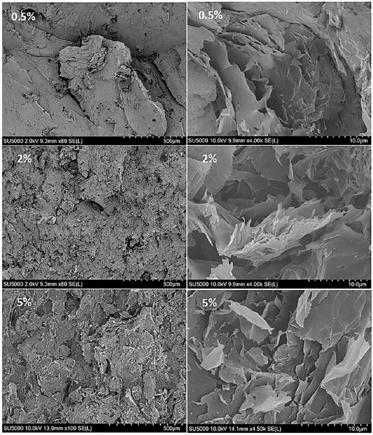
FIGURE 1. SEM images of the neat PEEK and the composites containing 0.5, 2 and 5 vol% EG.
A frequency sweep test in the range of 0.01–100 HZ was carried out to study the linear viscoelastic properties of the composite melts which was utilised to investigate the state of the EG platelet dispersion and structural change in the composites. Figures 2A,B show the variation of the storage modulus of the composites as a function of angular frequency and the EG volume fraction at a fixed frequency of 0.1 rad s−1, respectively. There are no particle contacts and sufficient space for the EG platelets to slip over each other, and their self-lubricant effect led to slipping and orientation of the polymer chains in the composites containing 0.5 and 1 vol% EG that caused to an unexpected decrease in their storage modulus compared with the neat PEEK at low and intermediate frequencies (Kim and Macosko 2009). However, the storage modulus of the 2 vol% of EG-loaded composite increased sharply and indicated a reduction in the dependence on angular frequency compared with the neat PEEK. This behaviour indicates the attainment of the rheological percolation threshold (
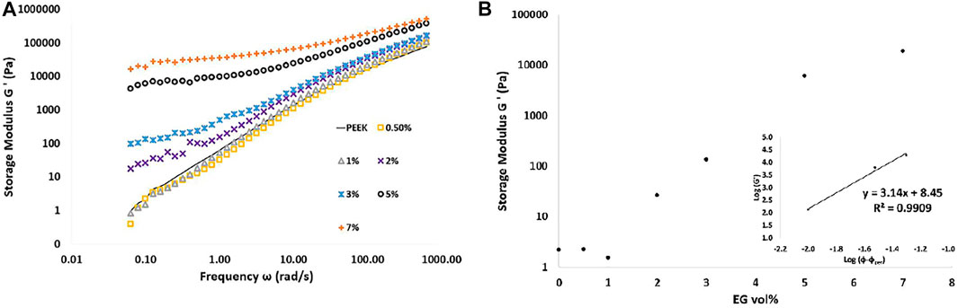
FIGURE 2. Storage modulus (A) of the PEEK/EG composite melts versus angular frequency for different EG loadings and (B) storage modulus as a function of the EG volume fraction at a fixed frequency of 0.1 rad s−1 at 370°C. Inset: log–log plot of the storage modulus versus the reduced volume fraction.
To gain a more detailed insight into the rheological percolation threshold, the relationship between storage modulus and filler volume fraction (φ) (φ >
where t is the critical exponent. As shown in the inset in Figure 2B, the composite modulus agreed well with the power law for the fixed frequency of 0.1 rad s−1, and the onset of percolation was determined as 0.02 volume fraction.
Figure 3A shows the variation of the complex viscosity as a function of angular frequency. At low and intermediate frequencies, fully relaxed neat PEEK chains and the composites containing 0.5 and 1 vol% EG exhibited a typical Newtonian viscosity plateau. With the addition of 2 vol% EG, the low frequency complex viscosity increases noticeably due to the restriction of the long-chain PEEK relaxations in the composites by the EG platelets. Hence, the Newtonian plateau vanishes progressively, and a significant shear-thinning behaviour is observed (Wagener and Reisinger 2003).
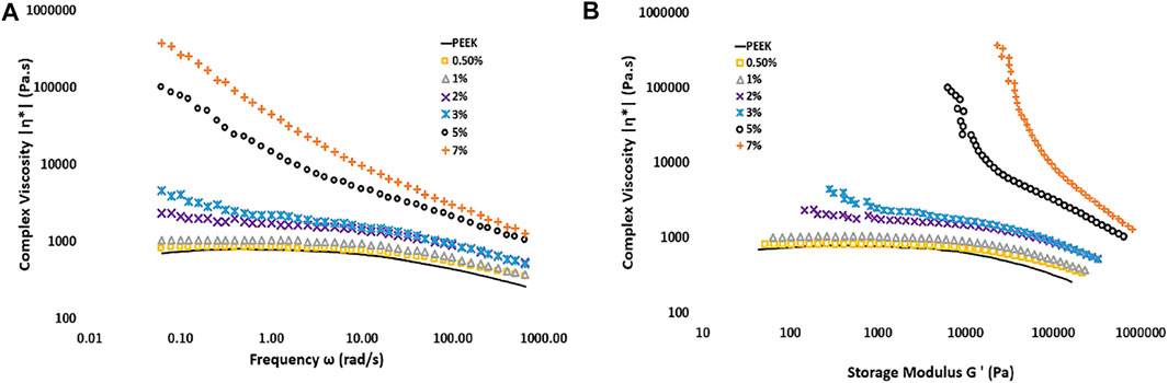
FIGURE 3. Complex viscosity of the PEEK/EG composite melts (A) versus angular frequency (B) versus storage modulus for different EG loadings at 370°C.
Also, a pseudo-solid-like network of an anisometric filler in a polymer matrix indicates an apparent yield stress which is obvious by plotting complex viscosity versus the complex modulus. In Figure 3B, an apparent yield stress in composites containing EG of more than 2 vol% observed that the complex viscosity increased rapidly as the complex modulus decreased (Cassagnau 2008; Abbasi et al., 2009).
The dynamic crystallisation behaviour of semicrystalline thermoplastic composites is of great interest since most processing methods happen under these conditions, and the crystal perfection and crystallinity degree of these materials depend on thermal history imparted during processing (Wu et al., 2007; Zhao et al., 2011). Figure 4 and Table 1 show the results of non-isothermal DSC tests that were carried out at 10°C/min to evaluate the influence of the EG content and processing conditions on the crystallisation and melting behaviour of the PEEK matrix.
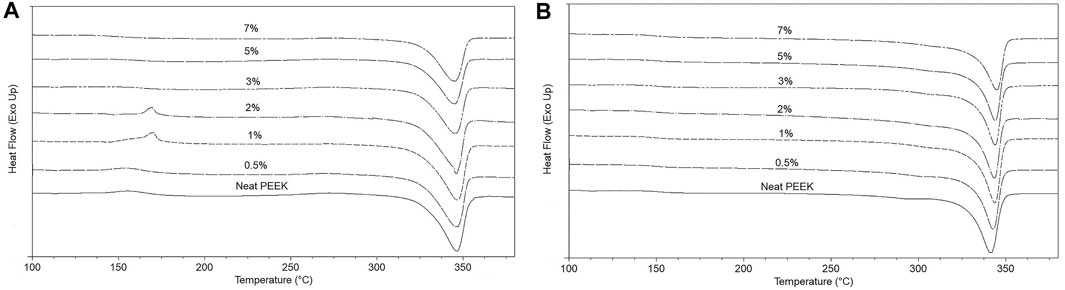
FIGURE 4. DSC results of the neat PEEK and the composite samples at 10°C/min (A) the first heating scan (B) the second heating scan.
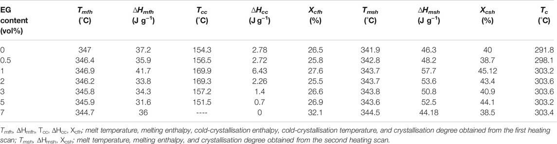
TABLE 1. Non-isothermal crystallisation parameters of PEEK/EG composites obtained from the DSC measurements.
Post or cold crystallisation is due to a physical aging process which typically happens in semicrystalline thermoplastics around the glass transition region due to a thermodynamically unstable state caused by cooling conditions during processing. In cold crystallisation, changes in the physical structure of chains occur at either transition zones between the existing crystals and the amorphous regions or the imperfect existing crystalline structures which lead to an increase in the crystallinity degree and lamella thickness as well as to the perfection of the existing crystal structure (Wang et al., 2003; Antoniadis et al., 2009). The appearance of the cold-crystallisation peak in the first heating scan and a noticeable difference between the values of the melting enthalpies and crystallisation degrees of the samples in the first and second heating scans (except sample containing 7 vol% EG) verified that the cooling process in the mould of the injection moulder did not provide enough time for the PEEK chains to form a thermodynamically stable crystalline structure. The neat PEEK and the composites containing 0.5 vol% EG showed a broad cold-crystallisation peak which overlapped with the glass transition region. However, with an increase in the EG content to 1 and 2 vol%, the peak was sharper and happened at a higher temperature. EG platelets can affect crystallisation behaviour of the PEEK matrix through a nucleation effect and by altering the mobility of the PEEK chain segments via a confinement effect (Zhang et al., 2008; Rong et al., 2010). At the loadings of 1 and 2 vol% EG, the nucleation effect was dominant with EG platelets providing heterogeneous nucleation sites with lower energy for the PEEK chains to crystalise faster compared to the neat PEEK and the 0.5 vol% EG-loaded composites. However, the PEEK chains were not able to crystalise perfectly and became thermodynamically unstable due to the fast cooling in the mould. After a reheating to around Tg in the first heating scan of the DSC test, the frozen imperfect crystals could rearrange to a thermodynamically stable state, release heat, and equilibrating to a lower free energy. Hence, visible and sharp cold-crystallisation peaks appeared.
At the higher EG loadings, the PEEK chains could not crystalise as much as the chains of the samples with lower EG loadings (samples 1 and 2%) due to the dominance of the chain mobility confinement effect. Hence, during the reheating to around Tg in the first heating scan of the DSC test, fewer frozen imperfect crystals were available for rearrangement compared to the samples with lower EG loadings. Therefore, the cold-crystallisation degree decreased, and its peak moved to lower temperatures and disappeared in the sample containing 7 vol% EG.
Based on the first heating scan results, the crystallinity degree of the composite containing 7 vol% EG increased remarkably compared with the neat PEEK while the crystallinity degree of other composites changed slightly. The 7 vol% of EG-loaded composite did not show the cold-crystallisation peak in the first heating scan which means the cooling rate in the mould was slow enough for the PEEK chains to form thermodynamically stable crystals that did not rearrange in the first heating cycle. Also, the crystallinity degrees and melt temperatures of this composite in the first and second heating scans were similar. The estimated crystallinity degree from the second heating scan was related to the crystals that were formed in the cooling scan after removing the thermal and stress histories of the PEEK chains in an isothermal step at 390°C. By comparison of the crystallinity degrees of all samples in the first and heating scans, the PEEK chains crystalised more perfectly to a thermodynamically stable state in the cooling scan of the DSC test compared with the cooling process in the mould since they did not have a cold-crystallisation peak in the second heating cycle. Hence, it can be concluded that the formed crystalline structure of the injection moulded 7 vol% of EG composite was perfect enough, and its crystallinity degree increased compared with the neat PEEK due to heterogeneous crystallisation.
The significantly higher crystallinity degree of the samples in the second heating scan than the first one indicates that annealing can have a strong effect on the reduction of defects in the crystals of processed PEEK and can lead to an enhancement of their mechanical performance.
Based on a comparison between the melt temperatures of the samples (apart from the sample 7%) in the first and second heating scans of the DSC test in Table 2 and Figures 4A,B, crystals formed in the cooling process in the mould melted at a higher melt temperature and showed a broader endothermic melting peak as compared with the crystals formed in the cooling scan. This can be ascribed to the crystal perfection in the recrystallisation during the first heating scan that can increase the thickness of lamellae and the existence of a broad distribution of lamellae sizes due to the imperfect crystallisation in the cooling process in the mould. Also, it is worth noting that the composites in the first heating scan have slightly lower melt temperatures than the neat PEEK while the composites in the second heating scan have slightly higher melt temperature than the neat PEEK thus showing the strong effect of the cooling rate on the crystal structures.
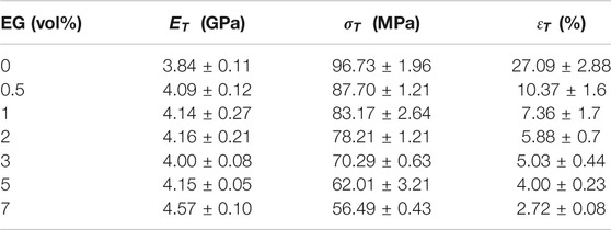
TABLE 2. Tensile properties of the composites:
As presented in Table 1, the crystallisation temperature of the composites increased remarkably due to the nucleation effect of the EG platelets. It is clear from the results of the second heating scans that the composites have slightly higher melt temperatures due to higher values of Tc that led to fewer defects in the PEEK crystals, and the crystallinity degrees of the composites were higher than the neat PEEK due to heterogeneous crystallisation. Also, the crystallinity degree increased up to the rheological percolation threshold and then dropped due to the formation of a filler network at percolation which reduced chain mobility. Beyond the rheological percolation threshold, the value of crystallinity of the composite containing 5 vol% EG increased due to nucleation promotion (Alvaredo et al., 2019).
Figure 5 shows the room temperature tensile and flexural stress-strain curves for the neat PEEK and the PEEK/EG composites, and Table 2 and Table 3 present the influence of EG loading on the average tensile and flexural properties of the samples. In the tensile stress-strain curve, the neat PEEK presented a yield stress of 96.73 ± 1.96 MPa after an elastic region with a Young’s modulus of 3.84 ± 0.11 GPa, a neck-formed region, neck propagation at a constant stress without strain hardening, and a final break at an elongation of 27.09 ± 2.88%. While the composites exhibited a linear elastic behaviour, which was followed by plastic deformation before fracture, the kink at about 20.6% tensile strain in the neat PEEK is the point where the extensometer was detached from the specimen. Also, the flexural stress-strain diagram of the neat PEEK shows an initial elastic region with flexural modulus of 3.55 ± 0.1 GPa which is followed by an ultimate strength of 156.41 ± 3.05 MPa and finally fractured at a strain of 12.90 ± 0.22%. As expected, stress-strain diagrams of the composites indicate a positive link between EG volume fraction and tensile and flexural moduli. The incorporation of 7 vol% EG into the PEEK increased the tensile and flexural moduli to 4.57 ± 0.10 and 4.92 ± 0.04 GPa which correspond to increases of 19 and 39% in stiffness, respectively.
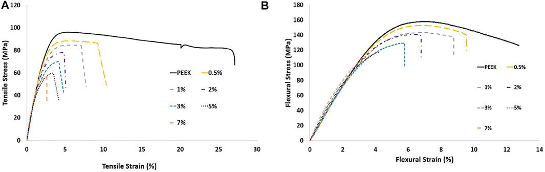
FIGURE 5 . (A) stress-strain curves from uniaxial tensile tests and (B) stress-displacement curves from 3-point bending tests of the neat PEEK and the PEEK/EG composites.
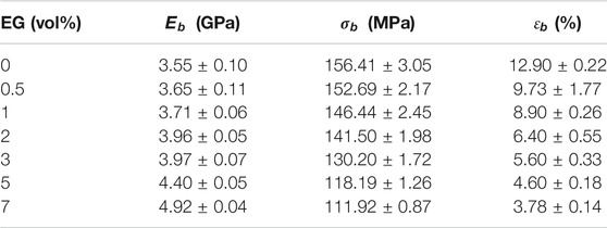
TABLE 3. Flexural properties of the composites:
According to the DSC results of the first heating cycle, crystallinity degree which directly affects the modulus of semicrystalline polymers did not change significantly as compared with the value of neat PEEK crystallinity apart from the sample containing 7 vol% EG (Díez-Pascual et al., 2019). Hence, the observed enhancements in the modulus of the composites with respect to the neat PEEK can be related to higher intrinsic modulus of the EG and its high aspect ratio which provided large interfaces with the matrix (Sever et al., 2013; Puértolas et al., 2019). However, the introduction of EG into the PEEK led to decreases in tensile and flexural strengths and fracture strains of the composites. The lower strength of the composites could be attributed to weak interfacial bonding at the interfaces of the EG galleries and the matrix and agglomerations of the EG platelets which caused a weak load transfer between the EG platelets and the PEEK matrix (Fukushima et al., 2010; Song, Xiao, and Meng 2006; Zhao et al., 2007). Also, the incorporation of the EG platelets into the PEEK remarkably hindered the motions of polymer chains such that the imposed external mechanical energy could not be dissipated effectively and led to the lower strength and significantly smaller fracture strains of the composites (Hatui et al., 2014).
Figure 6 presents the variation of the volumetric wear rate of the neat PEEK and the composites. It can be seen from Figure 6 that the wear rate of the neat PEEK decreased from 30 to 18.87 mm3 m−1 by the incorporation of the 3 vol% EG which corresponds to 37% improvement in the wear resistance. After reaching the critical volume fraction of 3 vol%, further increase in the EG content resulted in a higher wear rate.
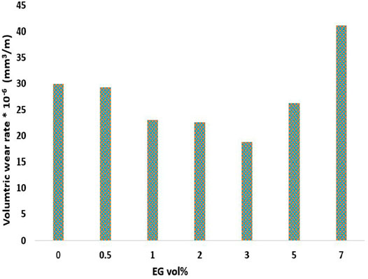
FIGURE 6. Volumetric wear rate of the neat PEEK and the PEEK/EG composites.
With the gradual increase of the EG content, the contact zone between the composites and steel ball counterpart covered not only the PEEK matrix but also the EG platelets. Before reaching the critical volume fraction, the PEEK matrix contributed more than the EG galleries to decreasing the wear rate of the composites. The PEEK matrix with its outstanding mechanical properties and high strength and ductility in the interfacial regions provided local support for the EG galleries and absorbed the shear energy of the steel ball counterpart. This reduced the probability of the fracture of large EG particles from the composite’s surfaces. Hence, they could enhance and decrease the anti-friction character and the wear rate of the composite, respectively, by peeling off in tiny particles and forming a lubricant film on the composite’s surface. After a loading of EG platelets more than the critical volume fraction, EG platelets contribute more than the PEEK matrix to the wear resistance of the composite. Hence, the poor shear strength of the EG platelets and the reduction of the strength and ductility of the matrix at the interfacial regions which deformed through elongation rather than breakage aggravate the wear performance of the composites (Zhao et al., 2007; Puértolas et al., 2019). However, if the volume fraction of the EG is less than the critical volume fraction, there are not enough EG galleries to decrease the friction between the matrix and the steel ball counterpart and form a lubricant film. Therefore, the wear resistance would be also low (Hu et al., 2005).
Moreover, as shown in Figure 7 the worn surfaces of the neat PEEK and the composites containing 3 and 7 vol% of EG which indicated the best and worse wear resistance were analysed via SEM to provide more information about the wear mechanism of the PEEK/EG composites. As shown in Figures 7A,D, the neat PEEK deformed and evident abrasive furrows on its worn surface formed due to the friction between the matrix and the steel ball counterpart. However, as shown in Figures 7B,C, the obvious furrows disappear in the worn surfaces of the composites, and they became smoother and flatter with an increase in the EG content. This can be ascribed to the fact that the graphite particles were peeled off and formed a lubricant film, reducing the direct contact between the matrix and counterpart and transferring the friction force to the graphite sheets (Wang et al., 2012). Figure 7E shows that the ductility and strength of the matrix at the interfacial regions of the 3 vol% of EG-loaded composite are high enough to provide local support for the EG galleries such that tiny EG particles are peeled off to form the lubricant film, and a small number of micro-cracks are formed on the composite surface (Jia et al., 2015; Sun et al., 2021). While, as shown in Figures 7C,F, more micro-cracks and the EG galleries are observed on the surface of the composite containing 7 vol% EG, this can be attributed to the fact that the EG galleries were directly chipped off the composite surface due to their poor shear strength and inadequate adhesion strength between the EG galleries and the matrix producing more aggravated wear of the composite as compared with the neat PEEK (Chang et al., 2006; Huang et al., 2008).
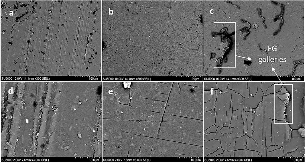
FIGURE 7. Low and high magnification SEM images of the worn surfaces of the neat PEEK (A,D) and the PEEK/EG composites containing 3 (B,E) and 7 (C,F) vol% EG.
An efficient way to prevent a build-up of electrostatic charge in high-temperature electrically conductive thermoplastic composite is the incorporation of thermally conductive carbon fillers (Díez-Pascual et al., 2010; Moniruzzaman and Winey 2006). In this work, EG platelets were incorporated into PEEK to increase its electrically conductivity. Figure 8 presents the effect of the EG content on the room temperature DC electrical conductivity values of the PEEK/EG composites. At low EG contents (≤3 vol%), the electrical conductivity values of the composites increased only slightly due to a large distance between the particles. However, the electrical conductivity value of the 5 vol% of EG-loaded composite increases suddenly to 3.2 × 10⁻⁵ S m−1 which is higher than the required electrical conductivity for antistatic applications (10−6 S m−1). This is due to the formation of electrically conductive paths caused by either direct particle-particle interactions or interfacial regions between particles with a distance shorter than the tunnelling distance (10 nm) in agreement with the SEM observations (Debelak and Lafdi 2007). No remarkable change was noticed with increasing the EG loading, which suggests the EG content is beyond the electrical percolation threshold. The electrical percolation threshold is significantly bigger than the rheological one. The difference can be ascribed to a shorter required filler-filler distance for electron tunnelling as the predominant mechanism of electrical conductivity as compared with that required for confinement of polymer chain motions at the rheological percolation threshold (Abbasi et al., 2009). Also, the electrical conductivity measurements were done on a room-temperature solid sample, whereas the rheological threshold was measured at temperatures above Tm so there is likely to be much more particleparticle contacts in the rheological measurement.
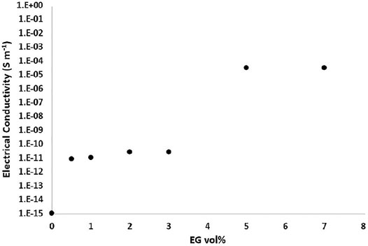
FIGURE 8. DC volume electrical conductivity of the PEEK/EG composites at room temperature.
PEEK/EG composites were prepared via twin-screw extrusion and subsequent injection moulding. The rheological and electrical percolation thresholds occurred at EG loadings of 2 and 5 vol%, respectively. Annealing of the PEEK composites can improve their mechanical performance. The incorporation of EG into PEEK increased its tensile and flexural modulus and decreased its tensile and flexural strengths and fracture stains. The composite containing 3 vol% of EG exhibited the maximum wear resistance. The electrical conductivity value at the electrical percolation threshold was in the required range of electrical conductivity for ESD materials.
The raw data supporting the conclusion of this article are available from the corresponding author upon reasonable request.
MM: conceptualisation, data curation, formal analysis, investigation, methodology, project administration, visualisation, writing—original draft, writing—review and editing. EA: conceptualisation, formal analysis, supervision, resources, project administration, writing—review, and editing. NB: conceptualisation, supervision, resources, writing—review and editing. EH-J: conceptualisation, formal analysis, supervision, resources, writing—review and editing. AM: conceptualisation, formal analysis, project administration, supervision, funding acquisition, resources, writing—review and editing.
The North West Centre for Advanced Manufacturing (NW CAM) project is supported by the European Union’s INTERREG VA Programme, managed by the Special EU Programmes Body (SEUPB). The views and opinions in this document do not necessarily reflect those of the European Commission or the Special EU Programmes Body (SEUPB). If you would like further information about NW CAM please contact the lead partner, Catalyst, for details.
Author NB was employed by company Denroy Plastics, United Kingdom.
The remaining authors declare that the research was conducted in the absence of any commercial or financial relationships that could be construed as a potential conflict of interest.
All claims expressed in this article are solely those of the authors and do not necessarily represent those of their affiliated organizations, or those of the publisher, the editors and the reviewers. Any product that may be evaluated in this article, or claim that may be made by its manufacturer, is not guaranteed or endorsed by the publisher.
Abbasi, S., Carreau, P. J., Derdouri, A., and Moan, M. (2009). Rheological Properties and Percolation in Suspensions of Multiwalled Carbon Nanotubes in Polycarbonate. Rheol. Acta 48, 943–959. doi:10.1007/s00397-009-0375-7
Aderikha, V. N., Krasnov, A. P., Naumkin, A. V., and Shapovalov, V. A. (2017). Effects of Ultrasound Treatment of Expanded Graphite (EG) on the Sliding Friction, Wear Resistance, and Related Properties of PTFE-Based Composites Containing EG. Wear 386-387, 63–71. doi:10.1016/j.wear.2017.04.022
Alvaredo, Á., Martín, M., Castell, P., Guzmán de Villoria, R., and Fernández-Blázquez, J. (2019). Non-Isothermal Crystallization Behavior of PEEK/Graphene Nanoplatelets Composites from Melt and Glass States. Polymers 11, 124. doi:10.3390/polym11010124
Antoniadis, G., Paraskevopoulos, K. M., Bikiaris, D., and Chrissafis, K. (2009). Kinetics Study of Cold-Crystallization of Poly(ethylene Terephthalate) Nanocomposites with Multi-Walled Carbon Nanotubes. Thermochim. Acta 493, 68–75. doi:10.1016/j.tca.2009.04.005
Arjmand, M., Apperley, T., Okoniewski, M., and Sundararaj, U. (2012). Comparative Study of Electromagnetic Interference Shielding Properties of Injection Molded versus Compression Molded Multi-Walled Carbon Nanotube/polystyrene Composites. Carbon 50, 5126–5134. doi:10.1016/j.carbon.2012.06.053
Bangarusampath, D. S., Ruckdäschel, H., Altstädt, V., Sandler, J. K. W., Garray, D., and Shaffer, M. S. P. (2009). Rheological and Electrical Percolation in Melt-Processed Poly(ether Ether Ketone)/multi-wall Carbon Nanotube Composites. Chem. Phys. Lett. 482, 105–109. doi:10.1016/j.cplett.2009.09.064
Blundell, D. J., and Osborn, B. N. (1983). The Morphology of Poly(aryl-Ether-Ether-Ketone). Polymer 24, 953–958. doi:10.1016/0032-3861(83)90144-1
Cao, N., Shen, W., Wen, S., and Liu, Y. (1996). Surface Properties of Expanded Graphite. Chemistry-Peking, 37–40.
Cassagnau, P. (2008). Melt Rheology of Organoclay and Fumed Silica Nanocomposites. Polymer 49, 2183–2196. doi:10.1016/j.polymer.2007.12.035
Chang, L., and Zhang, Z. (2006). Tribological Properties of Epoxy Nanocomposites. Wear 260, 869–878. doi:10.1016/j.wear.2005.04.002
Chen, G.-H., Wu, D.-J., Weng, W.-G., He, B., and Yan, W.-l. (2001). Preparation of Polystyrene-Graphite Conducting Nanocomposites via Intercalation Polymerization. Polym. Int. 50, 980–985. doi:10.1002/pi.729
Debelak, B., and Lafdi, K. (2007). Use of Exfoliated Graphite Filler to Enhance Polymer Physical Properties. Carbon 45, 1727–1734. doi:10.1016/j.carbon.2007.05.010
Dhakate, S., Sharma, S., Borah, M., Mathur, R., and Dhami, T. (2008). Expanded Graphite-Based Electrically Conductive Composites as Bipolar Plate for PEM Fuel Cell. Int. J. Hydrogen Energ. 33, 7146–7152. doi:10.1016/j.ijhydene.2008.09.004
Díez-Pascual, A. M., Naffakh, M., González-Domínguez, J. M., Ansón, A., Martínez-Rubi, Y., Martínez, M. T., et al. (2010). High Performance PEEK/carbon Nanotube Composites Compatibilized with Polysulfones-II. Mechanical and Electrical Properties. Carbon 48, 3500–3511. doi:10.1016/j.carbon.2010.05.050
Dong, X., Xu, H., Chen, H., Wang, L., Wang, J., Fang, W., et al. (2019). Commercial Expanded Graphite as High-Performance Cathode for Low-Cost Aluminum-Ion Battery. Carbon 148, 134–140. doi:10.1016/j.carbon.2019.03.080
Du, X. S., Xiao, M., Meng, Y. Z., and Hay, A. S. (2004). Synthesis and Properties of Poly(4,4′-Oxybis(benzene)disulfide)/graphite Nanocomposites via In Situ Ring-Opening Polymerization of Macrocyclic Oligomers. Polymer 45, 6713–6718. doi:10.1016/j.polymer.2004.07.026
Flanagan, M., Grogan, D. M., Goggins, J., Appel, S., Doyle, K., Leen, S. B., et al. (2017). Permeability of Carbon Fibre PEEK Composites for Cryogenic Storage Tanks of Future Space Launchers. Composites A: Appl. Sci. Manufacturing 101, 173–184. doi:10.1016/j.compositesa.2017.06.013
Fukushima, K., Murariu, M., Camino, G., and Dubois, P. (2010). Effect of Expanded Graphite/layered-Silicate clay on thermal, Mechanical and Fire Retardant Properties of Poly(lactic Acid). Polym. Degrad. Stab. 95, 1063–1076. doi:10.1016/j.polymdegradstab.2010.02.029
Goyal, R. K. (2013). Cost-efficient High Performance Polyetheretherketone/expanded Graphite Nanocomposites with High Conductivity for EMI Shielding Application. Mater. Chem. Phys. 142, 195–198. doi:10.1016/j.matchemphys.2013.07.005
Goyal, R. K., Samant, S. D., Thakar, A. K., and Kadam, A. (2010). Electrical Properties of Polymer/expanded Graphite Nanocomposites with Low Percolation. J. Phys. D: Appl. Phys. 43, 365404. doi:10.1088/0022-3727/43/36/365404
Hatui, G., Bhattacharya, P., Sahoo, S., Dhibar, S., and Das, C. K. (2014). Combined Effect of Expanded Graphite and Multiwall Carbon Nanotubes on the Thermo Mechanical, Morphological as Well as Electrical Conductivity of In Situ Bulk Polymerized Polystyrene Composites. Composites Part A: Appl. Sci. Manufacturing 56, 181–191. doi:10.1016/j.compositesa.2013.10.007
Hu, J., Li, D. Y., and Llewellyn, R. (2005). Computational Investigation of Microstructural Effects on Abrasive Wear of Composite Materials. Wear 259, 6–17. doi:10.1016/j.wear.2005.02.017
Huang, L., Zhu, P., Chen, Z., Song, Y., Wang, X., and Huang, P. (2008). Tribological Performances of Graphite Modified Thermoplastic Polyimide. Mater. Sci. Eng. Hangzhou 26, 268–272.
Jia, Z., Hao, C., Yan, Y., and Yang, Y. (2015). Effects of Nanoscale Expanded Graphite on the Wear and Frictional Behaviors of Polyimide-Based Composites. Wear 338-339, 282–287. doi:10.1016/j.wear.2015.06.019
Kalin, M., Zalaznik, M., and Novak, S. (2015). Wear and Friction Behaviour of Poly-Ether-Ether-Ketone (PEEK) Filled with Graphene, WS 2 and CNT Nanoparticles. Wear 332-333, 855–862. doi:10.1016/j.wear.2014.12.036
Kalra, S., Munjal, B. S., Singh, V. R., Mahajan, M., and Bhattacharya, B. (2019). Investigations on the Suitability of PEEK Material under Space Environment Conditions and its Application in a Parabolic Space Antenna. Adv. Space Res. 63, 4039–4045. doi:10.1016/j.asr.2019.03.006
Kim, H., and Macosko, C. W. (2009). Processing-property Relationships of Polycarbonate/graphene Composites. Polymer 50, 3797–3809. doi:10.1016/j.polymer.2009.05.038
Kim, H., Thomas Hahn, H., Viculis, L. M., Gilje, S., and Kaner, R. B. (2007). Electrical Conductivity of Graphite/polystyrene Composites Made from Potassium Intercalated Graphite. Carbon 45, 1578–1582. doi:10.1016/j.carbon.2007.02.035
Kurtz, S. M. (2019). PEEK Biomaterials Handbook. Philadelphia: William Andrew, Applied Science Publisher
Li, Y.-C., and Chen, G.-H. (2007). HDPE/expanded Graphite Nanocomposites Prepared via Masterbatch Process. Polym. Eng. Sci. 47, 882–888. doi:10.1002/pen.20772
Liebscher, M., Domurath, J., Saphiannikova, M., Müller, M. T., Heinrich, G., and Pötschke, P. (2020). Dispersion of Graphite Nanoplates in Melt Mixed PC/SAN Polymer Blends and its Influence on Rheological and Electrical Properties. Polymer 200, 122577. doi:10.1016/j.polymer.2020.122577
Mokhtari, M., Archer, E., Bloomfield, N., Harkin-Jones, E., and McIlhagger, A. (2021). High-performance and Cost-Effective Melt Blended Poly(ether Ether Ketone)/expanded Graphite Composites for Mass Production of Antistatic Materials. Polym. Int. 70, 1137–1145. doi:10.1002/pi.6226
Moniruzzaman, M., and Winey, K. I. (2006). Polymer Nanocomposites Containing Carbon Nanotubes. Macromolecules 39, 5194–5205. doi:10.1021/ma060733p
Noel, M., and Santhanam, R. (1998). Electrochemistry of Graphite Intercalation Compounds. J. Power Sourc. 72, 53–65. doi:10.1016/S0378-7753(97)02675-X
Pan, L., Liu, Z., kızıltaş, O., Zhong, L., Pang, X., Wang, F., et al. (2020). Carbon Fiber/poly Ether Ether Ketone Composites Modified with Graphene for Electro-thermal Deicing Applications. Composites Sci. Techn. 192, 108117. doi:10.1016/j.compscitech.2020.108117
Pei, X.-Q., Lin, L., Schlarb, A. K., and Bennewitz, R. (2019). Correlation of Friction and Wear across Length Scales for PEEK Sliding against Steel. Tribology Int. 136, 462–468. doi:10.1016/j.triboint.2019.04.001
Puértolas, J. A., Castro, M., Morris, J. A., Ríos, R., and Ansón-Casaos, A. (2019). Tribological and Mechanical Properties of Graphene Nanoplatelet/PEEK Composites. Carbon 141, 107–122. doi:10.1016/j.carbon.2018.09.036
Rival, G., Paulmier, T., and Dantras, E. (2019). Influence of Electronic Irradiations on the Chemical and Structural Properties of PEEK for Space Applications. Polym. Degrad. Stab. 168, 108943. doi:10.1016/j.polymdegradstab.2019.108943
Rong, C., Ma, G., Zhang, S., Song, L., Chen, Z., Wang, G., et al. (2010). Effect of Carbon Nanotubes on the Mechanical Properties and Crystallization Behavior of Poly(ether Ether Ketone). Composites Sci. Techn. 70, 380–386. doi:10.1016/j.compscitech.2009.11.024
Rozpłoch, F., Patyk, J., and Stankowski, J. (2007). Graphenes Bonding Forces in Graphite. Acta Phys. Pol. A. 112 (3), 557–562. doi:10.12693/APhysPolA.112.557
Sarathi, R., Sahu, R. K., and Rajeshkumar, P. (2007). Understanding the thermal, Mechanical and Electrical Properties of Epoxy Nanocomposites. Mater. Sci. Eng. A 445-446, 567–578. doi:10.1016/j.msea.2006.09.077
Schroeder, S., Braun, S., Mueller, U., Vogel, M., Sonntag, R., Jaeger, S., et al. (2020). Carbon-fibre-reinforced PEEK: An Alternative Material for Flexion Bushings of Rotating Hinged Knee Joints?. J. Mech. Behav. Biomed. Mater. 101, 103434. doi:10.1016/j.jmbbm.2019.103434
Sever, K., Tavman, İ. H., Seki, Y., Turgut, A., Omastova, M., and Ozdemir, I. (2013). Electrical and Mechanical Properties of Expanded Graphite/high Density Polyethylene Nanocomposites. Composites B: Eng. 53, 226–233. doi:10.1016/j.compositesb.2013.04.069
Song, L. N., Xiao, M., and Meng, Y. Z. (2006). Electrically Conductive Nanocomposites of Aromatic Polydisulfide/expanded Graphite. Composites Sci. Techn. 66, 2156–2162. doi:10.1016/j.compscitech.2005.12.013
Souza, J. C. M., Bentes, A. C., Reis, K., Gavinha, S., Buciumeanu, M., Henriques, B., et al. (2016). Abrasive and Sliding Wear of Resin Composites for Dental Restorations. Tribology Int. 102, 154–160. doi:10.1016/j.triboint.2016.05.035
Stack, M. M., and Mathew, M. (2003). Micro-abrasion Transitions of Metallic Materials. Wear 255, 14–22. doi:10.1016/S0043-1648(03)00204-7
Sun, Z., Zhao, Z.-K., Zhang, Y.-Y., Li, Y.-Q., Fu, Y.-Q., Sun, B.-G., et al. (2021). Mechanical, Tribological and thermal Properties of Injection Molded Short Carbon Fiber/expanded Graphite/polyetherimide Composites. Composites Sci. Techn. 201, 108498. doi:10.1016/j.compscitech.2020.108498
Wagener, R., and Reisinger, T. J. G. (2003). A Rheological Method to Compare the Degree of Exfoliation of Nanocomposites. Polymer 44, 7513–7518. doi:10.1016/j.polymer.2003.01.001
Wang, L., Zhang, L., and Tian, M. (2012). Effect of Expanded Graphite (EG) Dispersion on the Mechanical and Tribological Properties of Nitrile Rubber/EG Composites. Wear 276-277, 85–93. doi:10.1016/j.wear.2011.12.009
Wang, Y., Shen, C., and Chen, J. (2003). Nonisothermal Cold Crystallization Kinetics of Poly(ethylene Terephthalate)/Clay Nanocomposite. Polym. J. 35, 884–889. doi:10.1295/polymj.35.884
Weng, W., Chen, G., Wu, D., Chen, X., Lu, J., and Wang, P. (2004). Fabrication and Characterization of Nylon 6/foliated Graphite Electrically Conducting Nanocomposite. J. Polym. Sci. B Polym. Phys. 42, 2844–2856. doi:10.1002/polb.20140
Wu, D., Wu, L., Wu, L., Xu, B., Zhang, Y., and Zhang, M. (2007). Nonisothermal Cold Crystallization Behavior and Kinetics of Polylactide/clay Nanocomposites. J. Polym. Sci. B Polym. Phys. 45, 1100–1113. doi:10.1002/polb.21154
Yang, Y.-l., Jia, Z.-n., Chen, J.-j., and Fan, B.-l. (2010). Tribological Behaviors of PTFE-Based Composites Filled with Nanoscale Lamellar Structure Expanded Graphite. J. Tribol. 132 (3), 031301. doi:10.1115/1.4001546
Zhang, G., Schlarb, A. K., Tria, S., and Elkedim, O. (2008). Tensile and Tribological Behaviors of PEEK/nano-SiO2 Composites Compounded Using a ball Milling Technique. Composites Sci. Techn. 68, 3073–3080. doi:10.1016/j.compscitech.2008.06.027
Zhang, H.-B., Zheng, W.-G., Yan, Q., Jiang, Z.-G., and Yu, Z.-Z. (2012). The Effect of Surface Chemistry of Graphene on Rheological and Electrical Properties of Polymethylmethacrylate Composites. Carbon 50, 5117–5125. doi:10.1016/j.carbon.2012.06.052
Zhang, J., Tian, W., Chen, J., Yu, J., Zhang, J., and Chen, J. (2019). The Application of Polyetheretherketone (PEEK) Implants in Cranioplasty. Brain Res. Bull. 153, 143–149. doi:10.1016/j.brainresbull.2019.08.010
Zhao, Y. F., Xiao, M., Wang, S. J., Ge, X. C., and Meng, Y. Z. (2007). Preparation and Properties of Electrically Conductive PPS/expanded Graphite Nanocomposites. Composites Sci. Techn. 67, 2528–2534. doi:10.1016/j.compscitech.2006.12.009
Zhao, Y., Qiu, Z., Yan, S., and Yang, W. (2011). Crystallization Behavior of Biodegradable poly(L-Lactide)/multiwalled Carbon Nanotubes Nanocomposites from the Amorphous State. Polym. Eng. Sci. 51, 1564–1573. doi:10.1002/pen.21933
Keywords: high-temperature composite, cost-effective, expanded graphite, antistatic, wear resistance, cold-crystallization
Citation: Mokhtari M, Archer E, Bloomfield N, Harkin-Jones E and Mcilhagger A (2021) Melt-Blended Multifunctional PEEK/Expanded Graphite Composites. Front. Mater. 8:724958. doi: 10.3389/fmats.2021.724958
Received: 14 June 2021; Accepted: 12 August 2021;
Published: 15 September 2021.
Edited by:
Jiabin Shen, Sichuan University, ChinaCopyright © 2021 Mokhtari, Archer, Bloomfield, Harkin-Jones and Mcilhagger. This is an open-access article distributed under the terms of the Creative Commons Attribution License (CC BY). The use, distribution or reproduction in other forums is permitted, provided the original author(s) and the copyright owner(s) are credited and that the original publication in this journal is cited, in accordance with accepted academic practice. No use, distribution or reproduction is permitted which does not comply with these terms.
*Correspondence: Mozaffar Mokhtari, bS5tb2todGFyaUB1bHN0ZXIuYWMudWs=, bW96YWZmYXIubW9raHRhcmlAZ21haWwuY29t
Disclaimer: All claims expressed in this article are solely those of the authors and do not necessarily represent those of their affiliated organizations, or those of the publisher, the editors and the reviewers. Any product that may be evaluated in this article or claim that may be made by its manufacturer is not guaranteed or endorsed by the publisher.
Research integrity at Frontiers
Learn more about the work of our research integrity team to safeguard the quality of each article we publish.