
94% of researchers rate our articles as excellent or good
Learn more about the work of our research integrity team to safeguard the quality of each article we publish.
Find out more
ORIGINAL RESEARCH article
Front. Mater., 10 August 2021
Sec. Mechanics of Materials
Volume 8 - 2021 | https://doi.org/10.3389/fmats.2021.701205
This article is part of the Research Topic2021 Retrospective: Mechanics of MaterialsView all 9 articles
 Jianbo Tang1
 Gang Zhao2
 Jun Wang3
 Yue Ding3
 Yajie Feng3Yunsheng Chen3Chao Zhang3Qing Huang3Shiqing Xin1*Jian Xu3,2*
The filament winding process is a competitive performing technology for nuclear fuel cladding tubes due to its high automation. The study of the yarn path on the mandrel surface is vital to design and produce the cladding tube with the desired mechanical properties, reducing manufacturing time and costs. The geodesic and semi-geodesic trajectories are used to create a 3D yarn path in this paper. A 3D yarn path optimization method based on the principle of minimum potential energy is proposed to simulate the overlap effect in accord with the real winding process. The finite element (FE) mesh based on the 3D yarn path has been used for the mechanical analysis of the cladding tube. The embedded region constraint is applied to define the interaction between the matrix mesh and the yarn mesh to model the meso-structure of the cladding tube. Based on the meso-scale FE model, the mechanical behavior of the wound SiCf/SiC nuclear fuel cladding tube is studied in detail. The results show that due to the neglect of the overlap effect, the conventional laminate model overestimates the cladding tube strength. The proposed meso-scale FE model can accurately predict the failure of the cladding tube. The results also confirm that the creation of a 3D yarn path and the derived meso-scale FE model, representing an accurate wound structure, are of importance to the prediction of the performance of the cladding tube.
Continuous SiC fiber-reinforced SiC matrix (SiCf/SiC) composites have been used in high temperature applications, such as nuclear fuel cladding tubes and aerospace propulsion systems (Naslain, 2004). Similar to other fiber-reinforced composites, the properties of SiCf/SiC composites mainly depend on the parameters of the fiber reinforcement, including fiber volume fraction, fiber orientation, and fiber architecture. In most cases, relatively high fiber volume fractions can be achieved by optimizing the performing process. As a result, the design of the fiber architecture and fiber orientation is essential to improve the comprehensive mechanical properties of the tubular cladding (Katoh et al., 2014). Three suitable performing processes are generally adopted for cladding tubes, including filament winding, 2D braiding, and 3D braiding (Sauder, 2014). The highest fiber volume fraction and strength are obtained by the filament winding (Figure 1) (Kim et al., 2015a). Moreover, the winding process can offer better yarn placement accuracy, and the fiber breakage will be minimized by eliminating yarn-to-yarn friction compared with braiding. Consequently, the winding process is a competitive processing technology for the cladding tube performing.
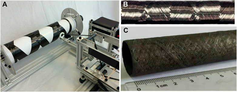
FIGURE 1. The filament winding technique for nuclear fuel cladding tube. (A) Filament winding process on a 4-axis filament winding machine. (B) SiC fiber wound preform (Kim et al., 2015a); (C) SiCf/SiC nuclear fuel cladding tube.
Due to the high degree of automation, the winding process is an economical and rapid performing technology for the cladding tube. Nonetheless, it lacks an efficient design process that takes specific processing parameters into account. The processing parameters of the winding process determine the properties of the wound tube, such as the coverage rate, winding angle, areal weight, and so on. Since the cost of SiCf/SiC composite forming is high, the trial-and-error method is more unaffordable compared with resin-based composites. Therefore, the gap between the properties and processing parameters has to be bridged using a numerical processing model in which the fiber architecture can be precisely captured. Then, the mechanical properties of the cladding tubes can be optimized and precisely predicted by meso-scale FE model.
In order to predict the fiber architecture in a wound structure, it is crucial to study the winding trajectory during the winding process. Simões et al. (1993) visualized the winding trajectory (geodesic and non-geodesic) as a polyline and simplified the mandrel shape as a wireframe model. However, only a single winding trajectory was simulated, rather than a path showing the width of the yarn. Several works of the literature (Hongya et al., 2007; Xianfeng et al., 2010; Zu et al., 2012) used a similar approach to simulate the winding process for other mandrel shapes, such as toroidal tanks, S-elbows, aircraft inlets, and vanes. Nonetheless, they were not real filament winding simulations because no consideration was given to the cross-section shape of yarn in the model. The paths of yarns on the elbow were generated by Li et al. (2005), while all the yarns appeared on the same layer, ignoring overlap effect. During the winding process, the former winding yarns are always covered by the latter ones. Fu et al. (2016) developed an algorithm to visualize the winding process of axisymmetric vessels in real-time, facilitating the engineers to check whether the distribution of yarns is reasonable and whether there is any collision during the winding process. The visualization simulation of the latter yarns covering the former yarns was achieved by OpenGL graphics display technology. The thickness of the yarns was also not taken into consideration in the simulation, in which the paths were always on the original mandrel surface. In fact, the yarns stack up on the mandrel surface as the winding process proceeds, leading to a renewal of the mandrel surface. These simulations fail to model the phenomenon of yarns accumulation on the mandrel surface, leading to the fact that real yarn architecture in the wound parts cannot be obtained from the simulation results. In other words, it is just a pseudo-3D filament winding simulation. For the accurate prediction of the cladding tube mechanical properties, real yarn architecture is necessary for meso-scale FE model. Several works of the literature focus on the effect of winding angle on the wound tube mechanical properties with conventional laminate model while ignoring the effect of the real yarn architecture (Gunasegaran et al., 2013; Sulaiman et al., 2013).
This work develops an efficient virtual tool based on computational geometry for the design of the SiCf/SiC-cladding tubes, whose reinforcements are performed using the filament winding technique. The real yarn architecture modeling includes the generation of 3D yarn paths and overlap between yarns. The geodesic and semi-geodesic trajectories are developed to generate the 3D yarn paths totally covering the mandrel. Then, the L-BFGS algorithm is applied to path optimization, which can obtain the real 3D yarns architecture with an overlap effect. With real yarns architecture, the embedded region constraint is used in the meso-scale FE modeling. The meso-scale FE model can avoid the weakness of the laminate model, which ignores the overlap effect.
To simplify the process of modeling the 3D path of a wound yarn, a reasonable procedure is to first calculate the trajectory of the yarn centerline and then assign a yarn width and thickness to the centerline. The process of calculating the yarn centerline involves calculating the geodesic and semi-geodesic on the mandrel surface, as well as the winding pattern generation. As shown in Figure 2A, the yarn centerline consists of three kinds of trajectories, which are circular arc, helix, and semi-geodesic. When the cylindrical surface is expanded into a rectangle (Figure 2B), both the arcs and the helixes are shown as straight lines, for they are both geodesics (the geodesic is a straight line after the developable surface is spread). In contrast, the semi-geodesics are shown as curves, which means that its winding angle, i.e., the angle from the meridional direction to the yarn direction (Koussios, 2004), varies according to the z-coordinate.
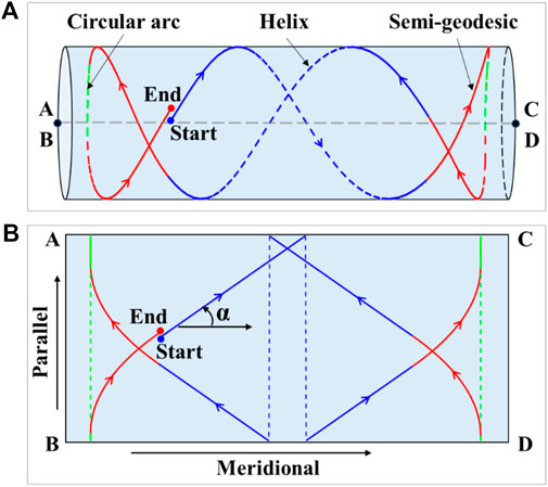
FIGURE 2. (A) Yarn centerline along one cycle on the cylindrical surface; (B) yarn centerline along one cycle after the cylindrical surface is spread.
A parametric representation of the helix and circle can be made by the following:
where R is the cylinder radius,
The semi-geodesic has a variable winding angle and is used to reverse yarn motion direction at both ends of the mandrel. However, compared with the geodesic, the semi-geodesic trajectory can lead to yarn slippage on the mandrel. In order to maintain the mechanical stability of the yarn, it is essential to ensure that the ratio of the frictional force and the normal pressure acting on the yarn is less than the friction coefficient μ between the yarn and the mandrel. This equilibrium condition could be expressed by differential geometric quantities, geodesic curvature, and the normal curvature, which can be written as follows (De Carvalho et al., 1995; Koussios, 2004; Koussios et al., 2004; Kim et al., 2005; Vargas Rojas et al., 2014):
where
Through integral
where
In order to maintain a constant length increment ds along the semi-geodesic, the step size of z is calculated in the following way:
The relationship between rotation angle
To have the yarn cover the mandrel uniformly, the total rotation angle experienced during a cycle must be designed according to the particular winding pattern. The winding pattern is formed by the yarn going back and forth along the mandrel and crossing and overlapping itself at certain points. Once the helix and semi-geodesic trajectories are determined, the yarn usually dwells in both ends of the mandrel when α = π/2 for a certain angle of
where
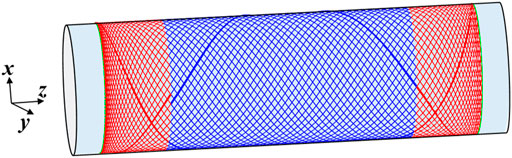
FIGURE 3. Yarn centerline along all cycles in one layer.
Many different yarn cross-sections have been presented over the years to indicate the actual condition of the yarn before and after tension is applied. These studies have mainly been carried out for representative volume elements (RVE) or advanced fiber placement (AFP) techniques (Potluri and Manan, 2007; Ansar et al., 2011; Kim et al., 2015b; Vernet and Trochu, 2016). Commonly used yarn cross-section shapes include rectangular, ellipsoidal, lenticular, and so on. However, in the filament winding process, the yarn is expanded into a flat shape with a rectangular cross-section. Hence, our work considers the yarn cross-section as a rectangular cross-section, and the shape remains consistent throughout the winding process.
As shown in Figure 4A, based on the centerline of the yarn path
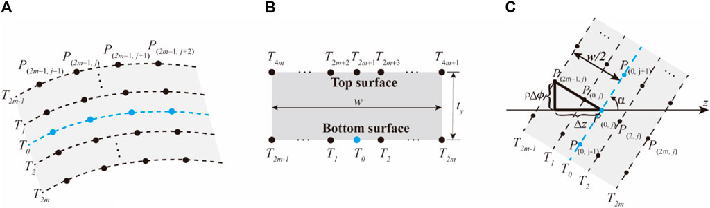
FIGURE 4. Representation of the width and thickness of a yarn. (A) Representation of the width of yarn; (B) yarn cross-section expressed as a rectangle; (C) position of multiple parallel trajectories of a yarn path in relation to the centerline.
On the cylindrical surface, the geodesic offsets are easy to calculate.
Points
Similarly, for points
As soon as the yarn crosses another part of itself in the winding process, overlap will occur. Assuming that the yarn is always in contact with the mandrel surface or a previous part of itself, a point on the current yarn path obtains a new radial distance
Figure 5 shows a schematic representation of the overlap processing of two yarns (yarn A and yarn B). Yarn A can be regarded as the part of the yarn wound first and yarn B as the part of the yarn wound later. If there is no overlap processing, yarn B interferes with yarn A at the intersection (Figure 5A), the paths of yarn A and B are on the original mandrel surface. It fails to represent the yarn accumulation on the mandrel surface. After eliminating interference, the 3D path of yarn B is shown in Figure 5B. Intuitively, it is clear that the behavior of yarn B does not conform to physical reality; its distance from the mandrel surface changes abruptly before and after crossing yarn A and therefore, its path appears discontinuous. The underlying reason for the discontinuity is that the radial distance of points on yarn B in the cylindrical coordinate is updated by integer multiples of the yarn thickness during the overlap process.
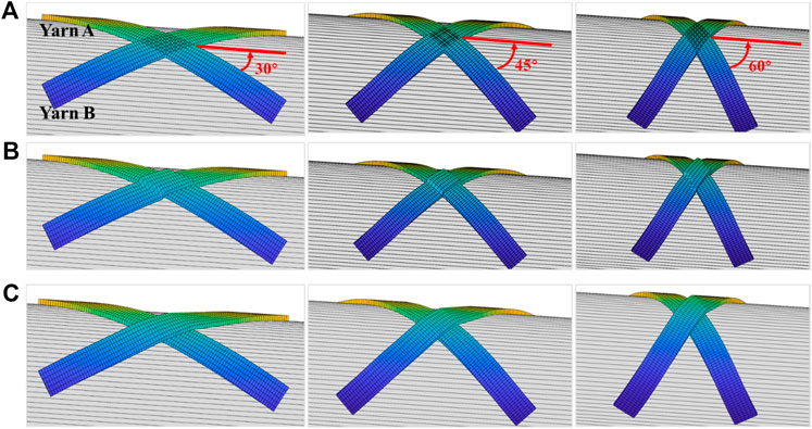
FIGURE 5. Generation of physically realistic 3D paths for yarns. (A) Before interference processing; (B) the discontinuous 3D paths of yarns after interference processing; (C) continuous 3D paths of yarns after optimization.
During the winding process, the yarn is subjected to winding tension. As a result, the tensioned yarn B temporarily leaves the mandrel surface before and after crossing the underlying yarn A. In a stable winding process, the mechanical behavior of the yarn should conform to the principle of minimum potential energy. It is important to note that the yarn sliding in the tangential direction receives a tension constraint and can be considered as having no tendency to slip (the friction force in this direction is zero), so the tension of the yarn can be considered as equal everywhere. Then the elongation of the yarn,
where F, E, and A denote the tension, the modulus in the length direction of the yarn, and the cross-section area of the yarn, respectively.
Ignoring first the cross-section of the yarn and denoting
For the displacement constraint of
where
According to the principle of minimum potential energy (Chandrupatla et al., 2002), under the displacement constraint, the potential energy can be used as the objective function, and the discrete connected system of yarn B will remain in mechanical equilibrium only when the potential energy of the whole system is minimized. Considering that the coefficient, E, A and
The physical meaning of Eq. 14 is that the equilibrium state of the yarn B, determined according to the principle of minimum potential energy, is in fact, also intuitively the shape of the shortest path of the yarn B.
It can be proven that the shortest total path is equivalent to the smallest sum of squared path lengths under the current constraint (the proof process is omitted here). Therefore, the objective function can be transformed into the following:
The new objective function,
Yarn B has a rectangular cross-section in practical optimization, and its 3D path consists of many trajectories
The square of the length of the line segment
The objective function
The value of
The optimized 3D path of the yarn is shown in Figure 5C. It can be seen that the shape of the yarn B becomes smooth and leaves the surface of the mandrel before and after crossing yarn A, conforming to physical reality.
As shown in Figure 6, the 3D path modeling strategy for wound yarn was applied to the fuel cladding tube. The main geometrical and processing parameters are listed below:
• The width and thickness of the SiCf yarn are 1.1 and 0.1 mm, respectively;
• The diameter of the mandrel is 20 mm the effective winding length is 100 mm;
• The winding angle is 45°and the winding pattern is 41/1.
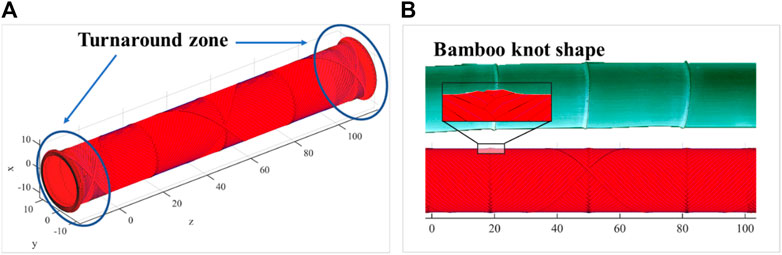
FIGURE 6. (A) Simulated 3D path of yarn in wound preform; (B) the winding pattern has a “bamboo knot” shape.
The simulated 3D path of yarn shows the “bamboo knot” structure of the wound part (Figure 6B). The winding path in the turnaround zone is semi-geodesic and the winding angle changes from the 45°to 90°, where yarn enrichment occurs and the thickness is, therefore, thicker than that in the other areas, which is also consistent with reality.
The 3D winding path already provides a geometric model of the yarn, which can be meshed to generate the meso-scale FE model. Based on the meso-scale FE model, the structural analysis can be performed. The numerical results of the wound tube model will be compared with the laminated tube model that is often used as a simplification. The discrepancies between these two models will be investigated in detail.
As seen in Figure 7A, the tube has a length of 100 mm, an inner diameter of 20 mm, and a wall thickness of 0.5 mm. The wound yarns have 153,504 C3D8R elements, and the matrix has 77,952 elements (Figure 7B), while the laminated tube has 103,936 elements (Figure 7C). The global fiber volume fraction is 28% for both wound and laminated tubes. The input material properties are listed in Table 1, calculated from the micro-UD model (Feng et al., 2020). The SiC matrix has Young’s modulus of 300 GPa and a Poisson ratio of 0.14.
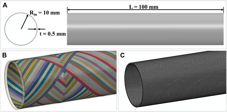
FIGURE 7. The FE model of the nuclear cladding tube: (A) the dimension of the tube with a length of 100 mm and a thickness of 0.5 mm; (B) the wound mesh integrated with the matrix using embedded constraint; (C) the laminated tube. The global fiber volume fractions are identical at 28%.

TABLE 1. Input mechanical properties for yarn and laminate, calculated from micro-UD model (Feng et al., 2020).
The embedded element technique is used to specify that an element or group of elements is embedded in “host” elements. As shown in Figure 8A, the matrix mesh is the host mesh, and the yarn mesh is the embedded mesh. Abaqus searches for the geometric relationships between nodes of the embedded elements and the host elements. If a node of an embedded element lies within a host element, the translational degrees of freedom at the node are eliminated and the node becomes an “embedded node.” The translational degrees of freedom of the embedded node are constrained to the interpolated values of the corresponding degrees of freedom of the host element (Tabatabaei et al., 2014). Figure 8B shows the displacement boundary conditions at both ends of the tube. The load is applied directly to the master node at the end of the tube. Then the master node transfers the load to the slave nodes at both ends of the tube through continuum distributing constraints by weight. Take the axial tension condition as an example, the three translational degrees of freedom of the left master node are set to zero, and the tension load is applied through the axial displacement of the right master node.
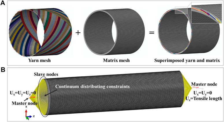
FIGURE 8. (A) Define the constraints between the yarn and the matrix by domain superposition technique; (B) displacement constraints at both ends of the tube.
With the obtained mesh (Figure 7B) and material properties (Table 1), the meso-scale FE model of the cladding tube can be applied to structural optimization. Generally, the model of the laminated tube with identical fiber orientations are often used to predict the major mechanical properties, e.g., apparent modulus and strength, as a simplified substitute. However, the weakening effect of the yarn waviness and interlocks caused by the overlap effect has not yet been specifically investigated in the previous work of cladding tube design. The mechanical stresses on the cladding tubes are small, and the main risk is the mechanical failure during a sudden axial movement (Sauder, 2014), which will result in axial tensile or compressive stresses. In addition, the weakness of the SiCf/SiC composite is the low shear strength, which is reflected in the axial tensile condition where the fiber direction is exactly the maximum shear stress. Therefore, in the following discussion, an equivalent tensile loading will be applied to the tube; the apparent moduli of the wound tube and laminated tube will be calculated and compared.
Figure 9A shows that the global axial tensile moduli of the wound and laminated tubes are quasi equivalent. The global tensile modulus of the laminated tube is 322.0 GPa, and the global tensile modulus of the wound tube is 322.2 GPa. The deviation is negligible. In such a circumstance, the meso-scale FE model can be used to predict the apparent moduli of the cladding tube, especially under complex service loadings.
FIGURE 9. The mechanical response of wound and laminated tubes under global axial tensile loading. (A) the global tension moduli; (B) the safety factor of shear stress.
Although the calculated moduli of the wound tube and the laminated tube present good agreement, the local stress states are totally different since the waviness and interlock of the yarn cause stress concentration, which will introduce an earlier damage initiation and final failure of the cladding tube. Shear stress is the typical stress state of the tube under axial tension and the shear stress safety factor is demonstrated in Figure 9B. The safety factor is defined as the ratio of the shear stress and shear strength (the shear strengths of SiCf/SiC are 60.1 and 78.8 MPa when the fiber volume fraction is 70 and 28% (Feng et al., 2020)). For the wound tube, the shear stress is extracted from the nodes along the yarn on which the maximum stress is located, and for the laminated tube, the shear stress is extracted from the nodes along the axial direction. According to our assumption, the safety factors in the wound yarns are almost 36.7% lower than that of the laminated tube. The lowest safety factor occurs at the “bamboo knot” in the yarn, which means that the damage initiation will occur here due to stress concentration caused by the overlap effect, which cannot be reflected in the laminated tube model. Figure 10A shows the global shear stress just before the damage of the yarn, and it can be seen that the maximum shear stress in the wound tube yarn is 20% greater than the stress in the laminated tube. At the same time, a higher fiber volume fraction will lead to a reduction in shear strength, so the difference in safety factor between the two models is greater than the difference in shear stress. In such a context, with the same fiber volume fraction, the wound tube and the laminated one have similar values of moduli but quite different apparent strengths. The stress concentration and higher local fiber volume fraction result in a lower strength for wound tubes. This result confirms that a precise wound structure on meso-scale is indispensable for the property prediction of the cladding tube.
FIGURE 10. The shear stresses of tubes. (A) wound tube; (B) laminated tube.
In this paper, an efficient filament winding virtual tool considering the overlap effect of the yarn for SiCf/SiC nuclear fuel cladding tube is developed, which not only stimulates the 3D yarn laying path on the mandrel surface but also generates a meso-scale FE model of the cladding tube. The centerline (geodesic and semi-geodesic) of the 3D yarn path is calculated based on the analytical method and then the path is obtained by offsetting the centerline in the width and thickness directions of the yarn increasing efficiency in trajectory calculation. An innovative overlap processing algorithm based on the principle of minimum potential energy is proposed to obtain a continuous 3D path, which reflects the real yarns architecture. The comparisons of the apparent mechanical properties between the proposed meso-scale FE model and the conventional laminated model prove that the laminated tube model overestimates the structural strength, which results from the laminated model ignoring the yarn overlap effect. Non-uniformity of fiber volume fraction can also lead to earlier damage. In conclusion, the stress concentration caused by the overlap effect must be considered and optimized in the design. In the future, the proposed filament winding virtual tool will be applied to study the mechanical properties of nuclear fuel cladding tubes under complex loading cases.
The original contributions presented in the study are included in the article/supplementary material. Further inquiries can be directed to the corresponding authors.
JT carried out the investigation, methodology, data curation, software, writing-original draft preparation, visualization, and formal analysis. GZ performed data curation, software, methodology, writing-reviewing, and editing. JW, YD, YF, YC, and CZ contributed to software and validation. SX did the implementation of the computer code and supporting algorithms and testing of existing code components. QH and JX carried out project administration, supervision, and funding acquisition. JX contributed to writing-reviewing and editing, project administration, supervision, and funding acquisition.
This work was supported by the National Natural Science Foundation of China (No. 52075526) and the Dalian University of Technology 2019 Discipline Platform Fund (No. 1000-82212201). The authors also gratefully acknowledge the National Key Research and Development Program (No.2018YFB1107500), the “Ningbo 3315 Plan Innovation Team” (No. 2017A-28-C), the “Transformational Technologies for Clean Energy and Demonstration,” and the Strategic Priority Research Program of the Chinese Academy of Sciences (No. XDA21010205).
The authors declare that the research was conducted in the absence of any commercial or financial relationships that could be construed as a potential conflict of interest.
All claims expressed in this article are solely those of the authors and do not necessarily represent those of their affiliated organizations, or those of the publisher, the editors and the reviewers. Any product that may be evaluated in this article, or claim that may be made by its manufacturer, is not guaranteed or endorsed by the publisher.
Ansar, M., Xinwei, W., and Chouwei, Z. (2011). Modeling Strategies of 3D Woven Composites: A Review. Compos. Structures 93 (8), 1947–1963. doi:10.1016/j.compstruct.2011.03.010
Chandrupatla, T. R., Belegundu, A. D., Ramesh, T., and Ray, C. (2002). Introduction to Finite Elements in Engineering. Upper Saddle River, NJ: Prentice-Hall.
De Carvalho, J., Lossie, M., Vandepitte, D., and Van Brussel, H. (1995). Optimization of Filament-Wound Parts Based on Non-geodesic Winding. Composites manufacturing 6 (2), 79–84. doi:10.1016/0956-7143(95)99647-b
Feng, Y., Wang, J., Shang, N., Zhao, G., Zhang, C., Tang, J., et al. (2020). Multiscale Modelling of SiCf/SiC Nuclear Fuel Cladding Based on FE-Simulation of Braiding Process. Front. Mater. 7, 473.
Fu, J., Yun, J., Kim, J.-S., and Jung, Y. (2016). Real-time Graphic Visualization of Filament Band Winding for Fiber-Reinforced Cylindrical Vessels. J. Compos. Mater. 50 (16), 2165–2175. doi:10.1177/0021998315602325
Gunasegaran, V., Prashanth, R., and Narayanan, M. (2013). Experimental Investigation and Finite Element Analysis of Filament Wound GRP Pipes for Underground Applications. Proced. Eng. 64, 1293–1301. doi:10.1016/j.proeng.2013.09.210
Hongya, F., Xianfeng, W., Zhenyu, H., and Yunzhong, F. (2007). Abnormal Shape Mould Winding. Chin. J. Aeronautics 20 (6), 552–558. doi:10.1016/s1000-9361(07)60081-8
Johansen, B. S., Lystrup, A., and Jensen, M. T. (1998). CADPATH: a Complete Program for the CAD-, CAE- and CAM-Winding of Advanced Fibre Composites. J. Mater. Process. Tech. 77 (1-3), 194–200. doi:10.1016/s0924-0136(97)00417-2
Katoh, Y., Ozawa, K., Shih, C., Nozawa, T., Shinavski, R. J., Hasegawa, A., et al. (2014). Continuous SiC Fiber, CVI SiC Matrix Composites for Nuclear Applications: Properties and Irradiation Effects. J. Nucl. Mater. 448 (1-3), 448–476. doi:10.1016/j.jnucmat.2013.06.040
Kim, B. C., Weaver, P. M., and Potter, K. (2015). Computer Aided Modelling of Variable Angle Tow Composites Manufactured by Continuous Tow Shearing. Compos. Structures 129, 256–267. doi:10.1016/j.compstruct.2015.04.012
Kim, C.-U., Kang, J.-H., Hong, C.-S., and Kim, C.-G. (2005). Optimal Design of Filament Wound Structures under Internal Pressure Based on the Semi-geodesic Path Algorithm. Compos. Structures 67 (4), 443–452. doi:10.1016/j.compstruct.2004.02.003
Kim, D., Lee, H.-G., Park, J. Y., and Kim, W.-J. (2015). Fabrication and Measurement of Hoop Strength of SiC Triplex Tube for Nuclear Fuel Cladding Applications. J. Nucl. Mater. 458, 29–36. doi:10.1016/j.jnucmat.2014.11.117
Koussios, S., Bergsma, O. K., and Beukers, A. (2004). Filament Winding. Part 1: Determination of the Wound Body Related Parameters. Composites A: Appl. Sci. Manufacturing 35 (2), 181–195. doi:10.1016/j.compositesa.2003.10.003
Li, H., Liang, Y., and Bao, H. (2005). CAM System for Filament Winding on Elbows. J. Mater. Process. Technol. 161 (3), 491–496. doi:10.1016/j.jmatprotec.2004.07.093
Naslain, R. (2004). Design, Preparation and Properties of Non-oxide CMCs for Application in Engines and Nuclear Reactors: an Overview. Composites Sci. Tech. 64 (2), 155–170. doi:10.1016/s0266-3538(03)00230-6
Nocedal, J. (1980). Updating Quasi-Newton Matrices with Limited Storage. Math. Comp. 35 (151), 773. doi:10.1090/s0025-5718-1980-0572855-7
Potluri, P., and Manan, A. (2007). Mechanics of Non-orthogonally Interlaced Textile Composites. Composites Part A: Appl. Sci. Manufacturing 38 (4), 1216–1226. doi:10.1016/j.compositesa.2006.04.008
Sauder, C. (2014). Ceramic Matrix Composites: Nuclear Applications, Ceramic Matrix Composites: Materials, Modeling and Technology, 609–646. doi:10.1002/9781118832998.ch22
Simões, J. A. O., Wu, S.-T., and Loseries, F. (1993). Visual Simulation of the Geodesic and Non-geodesic Trajectories of the Filament Winding, Graphics Modeling and Visualization in Science and Technology. Springer, 199–215. doi:10.1007/978-3-642-77811-7_16
Sulaiman, S., Borazjani, S., and Tang, S. H. (2013). “Finite Element Analysis of Filament-Wound Composite Pressure Vessel under Internal Pressure,” in IOP Conference Series: Materials Science and Engineering (IOP Publishing), 012061. doi:10.1088/1757-899x/50/1/012061
Tabatabaei, S. A., Lomov, S. V., and Verpoest, I. (2014). Assessment of Embedded Element Technique in Meso-FE Modelling of Fibre Reinforced Composites. Compos. Structures 107, 436–446. doi:10.1016/j.compstruct.2013.08.020
Vargas Rojas, E., Chapelle, D., Perreux, D., Delobelle, B., and Thiebaud, F. (2014). Unified Approach of Filament Winding Applied to Complex Shape Mandrels. Compos. Structures 116, 805–813. doi:10.1016/j.compstruct.2014.06.009
Vernet, N., and Trochu, F. (2016). Analysis and Modeling of 3D Interlock Fabric Compaction Behavior. Composites Part A: Appl. Sci. Manufacturing 80, 182–193. doi:10.1016/j.compositesa.2015.10.024
Xianfeng, W., Jun, X., and Liwei, W. (2010). Winding Pattern Design and Simulation of S-Elbow. Chin. J. Aeronautics 23 (5), 573–577. doi:10.1016/s1000-9361(09)60256-9
Keywords: nuclear fuel cladding, filament winding, potential energy, L-BFGS, SiCf/SiC composite
Citation: Tang J, Zhao G, Wang J, Ding Y, Feng Y, Chen Y, Zhang C, Huang Q, Xin S and Xu J (2021) Computational Geometry-Based 3D Yarn Path Modeling of Wound SiCf/SiC-Cladding Tubes and Its Application to Meso-Scale Finite Element Model. Front. Mater. 8:701205. doi: 10.3389/fmats.2021.701205
Received: 28 April 2021; Accepted: 08 July 2021;
Published: 10 August 2021.
Edited by:
Dongchan Jang, Korea Advanced Institute of Science and Technology, South KoreaReviewed by:
M. K. Samal, Bhabha Atomic Research Centre (BARC), IndiaCopyright © 2021 Tang, Zhao, Wang, Ding, Feng, Chen, Zhang, Huang, Xin and Xu. This is an open-access article distributed under the terms of the Creative Commons Attribution License (CC BY). The use, distribution or reproduction in other forums is permitted, provided the original author(s) and the copyright owner(s) are credited and that the original publication in this journal is cited, in accordance with accepted academic practice. No use, distribution or reproduction is permitted which does not comply with these terms.
*Correspondence: Shiqing Xin, eGluc2hpcWluZ0AxNjMuY29t; Jian Xu, eHVqaWFuMTAyOEBkbHV0LmVkdS5jbg==
Disclaimer: All claims expressed in this article are solely those of the authors and do not necessarily represent those of their affiliated organizations, or those of the publisher, the editors and the reviewers. Any product that may be evaluated in this article or claim that may be made by its manufacturer is not guaranteed or endorsed by the publisher.
Research integrity at Frontiers
Learn more about the work of our research integrity team to safeguard the quality of each article we publish.