 Bin Wang
 Wanjun Wang
 Zhaochun Li
94% of researchers rate our articles as excellent or good
Learn more about the work of our research integrity team to safeguard the quality of each article we publish.
Find out more
ORIGINAL RESEARCH article
Front. Mater., 01 June 2021
Sec. Smart Materials
Volume 8 - 2021 | https://doi.org/10.3389/fmats.2021.682215
This article is part of the Research TopicSynthesis, Characterization and Applications of Magneto-Responsive Functional MaterialsView all 11 articles
In the magnetorheological (MR) impact buffer system, the internal or external disturbance of the MR damper is one of the main factors that affect the buffer performance of the system. This study aims to suppress or eliminate the influence of the disturbance of the MR damper. The continuous terminal sliding mode control (CTSMC) strategy with a high gain has a strong antidisturbance ability. However, the high gain may cause fluctuation of the damping force of the system. Therefore, a composite control strategy of sliding mode active disturbance rejection control (ADRC) based on an extended state observer (ESO) is proposed in this study. The total disturbance of the system is estimated by the ESO in real time, and the estimated disturbance is used as a feedforward compensation to the controller to reduce the influence of disturbance on the system. The gain of the CTSMC law of the closed-loop system can be reduced. In addition, the Lyapunov stability criterion is used to ensure the stability of the proposed controller. In order to verify the performance of the proposed CTSMC controller on response speed, overshoot, and hysteresis suppression ability, the window function, square wave function, and multistep function are given as the inputs of the control system. To verify the performance of the proposed sliding mode ADRC for the MR impact buffer system, the mechanical model and the control model are established and simulated using MATLAB/Simulink. The simulation results show that the CTSMC controller has the fastest response time and no overshoot and can suppress the hysteresis nonlinearity of the MR device compared with the open-loop control, PID control, and fractional order PID control. The MR impact buffer system with the sliding mode ADRC obtained the minimum peak value of 4350N within the permitted buffer displacement range compared with the other three traditional control methods. That means the proposed control method in this study has the advantage on buffer performance for the MR impact buffer system.
With magnetorheological (MR) fluid as the working medium, MR dampers, a kind of semiactive control device with a new structure, have a simple mechanical structure, fast response speed at the millisecond level, low power consumption, damping force that can be continuously adjusted forward and backward in a wide range, etc. These excellent characteristics make them have broad application prospects in the fields of impact resistance and high-speed vibration reduction and have been initially applied in the fields of aerospace, vehicles, buildings, bridges, and civil engineering (Carlson, 2002; Liu et al., 2005; Wereley et al., 2011; Hughes et al., 2017; Guo et al., 2019; Tudon-Martinez et al., 2019; Du et al., 2020; Yoon et al., 2020). Currently, MR dampers are mainly used in low-speed, low-frequency random load scenarios. In recent years, the application of MR dampers in high-speed impact bumper systems has aroused great interest among researchers, for example, in the landing process of aircraft, the recoil process of weapons, and vehicle operation on bumpy roads (Ouyang et al., 2016; Shou et al., 2018; Bai et al., 2019; Yuan et al., 2019).
MR dampers, a low-cost small-size smart device that generates a big damping force, have been applied in the field of high-speed vibration damping, such as semiactive suspension systems of vehicles, aircraft landing cushion systems, and wave impact processes of speedboats. The MR intelligent suspension system plays an important role in improving vehicle damping, and the selection of suitable controllers can reduce the road-transmitted shocks, thus attracting the widespread attention of domestic and foreign researchers. M. Ahmadian of Virginia Tech University proposed that one of the key issues for the successful application of MR dampers in shock buffer control systems is what control strategy is used to make up for the lack of dampers (Ahmadian and Poynor, 2001). Choi and Wereley (2003, 2005, 2015) studied the response of MR damper suspension systems in military vehicles and automotive seats under impact load and developed a set of nonlinear semiactive control systems. Bai et al. (2012) designed a bidirectional controllable MR damper to improve the performance of impact and vibration by using the sky-hook control algorithm. Rahmat et al. (2019) designed a fast practical control (FPC) algorithm with less computational strength. The control performance of the system was compared by using the control algorithms of sky-hook and FPC under different levels of impact energy. The results show that compared with the sky-hook control, the FPC controller improves the impact response, acceleration response, and force response by about 17.73%, which can better reduce the impact energy. Dong et al. (2010) adopted the sky-hook control algorithm, hybrid controller, LQG controller, sliding mode controller, and fuzzy controller and compared the performance of vehicle vibration reduction using these five control algorithms under different road conditions. Sliding mode control has a significant damping effect. During the landing of helicopters, the pilots or passengers often suffer waist injuries due to the huge impact force. Therefore, researchers applied MR dampers as energy absorbers in aircraft damping systems and devoted considerable effort to control strategies in this system. Choi and Wereley (2003, 2015) successively proposed a sliding mode controller with good robustness for parameter variations and external disturbances and an optimal Bingham number control strategy, and they verified the effectiveness of the control strategies by experiment. Dong et al. from Chongqing University developed a new type of variable stiffness damper based on the MR damper and established the control model. The damping performance of the MR damper was evaluated by drop test. The experimental results show that an MR damper can effectively reduce the impact load of spring–mass (Dong et al., 2011). The above research progress shows that MR dampers are sufficiently feasible and advanced in the field of high-speed vibration damping. In addition, the large amount of effort put into this field has led to a good understanding of the control method of MR dampers under high-speed vibration damping.
However, the impact buffer system is usually subject to instantaneous large shock loads, with a short acting time and strong uncertainty, which makes the shock-resistant system more severe than the high-speed vibration damping system. As an important factor in the controlled damping force of the impact bumper systems, the control strategy of MR dampers has been discussed extensively. But there is little research about the control strategy of MR dampers due to the highly nonlinear, time-varying, and uncertain nature of the system parameters of MR dampers in impact loading applications. Browne et al. of General Motors carried out a series of 1.0–10 m/s velocity and magnetic field strength impact tests on MR fluids by using a free-flight falling tower device. The results showed that the damping force, displacement, and energy absorption of MR dampers are dependent on the strength of the applied magnetic field and can be adjusted by varying the strength of the applied magnetic field (Browne et al., 2009). The inherent hysteresis nonlinearity of the MR dampers makes it difficult to obtain the desired magnetic field strength. To compensate for the MR damper hysteresis, Li and Gong et al. designed an MR damper embedded in a Hall sensor and a hysteresis compensation system by using PID controllers to adjust the magnetic flux density. Experiments and simulations show that the measured flux density can track the set signal well and verify the effectiveness of the hysteresis compensation control algorithm in the MR impact buffer system (Li et al., 2019). M. Ahmadian et al. obtained different impact energies by releasing the drop hammers from different heights from the falling tower, producing an impact load with a maximum velocity of 6.604 m/s acting on the MR dampers, and experimentally controlling the recoil motion in the antirecoil device of large- and medium-caliber firearms. The results showed that the MR damper can effectively reduce the recoil force and improve the firing accuracy and the stability of the system (Goncalves et al., 2006; Ahmadian and Norris, 2008). Professor Wang Jiong from Nanjing University of Science and Technology studied the control algorithms of an MR damper under impact load. The delay fuzzy adaptive control, delay fuzzy PID control strategy, optimal buffer control strategy, and fuzzy control strategy have been proposed successively. The four control methods were verified by experiments and have a better buffer effect to improve the cushioning property of the MR damper recoil system compared with the passive control (Li and Wang, 2012). The above studies show that the effectiveness of MR dampers under impact buffer conditions has been verified experimentally, and valuable control methods were provided. However, there are some shortcomings in the control effect, such as the “platform effect,” where the output damping force–buffer displacement does not reach the optimum due to the initial peak value. One of the reasons for the unsatisfactory control effect may be that the MR damper is subject to various external and internal disturbances under the impact load. Domestic and foreign scholars mainly research the influence of temperature on the MR damper. Under the impact load, the MR damper experiences a great temperature change due to electromagnetic coil resistance heating and energy dissipation, while the temperature can affect the rheological properties of MR fluids significantly (McKee et al., 2011). The experimental results of Breese et al. with regard to MR dampers of different sizes showed that the peak damping force is significantly lower with the increase in temperature and pointed out that this was caused by the decrease in fluid viscosity (Gordaninejad and Breese, 1999). D.C. Batterbee’s research showed that the force/velocity and force/displacement characteristics of the MR damper are significantly affected by the temperature variation. The research also pointed out that the increased temperature increases the effective fluid stiffness and reduces the yield stress and post-yield viscosity characteristics (Batterbee and Sims, 2009). Xia Fan et al. from Nanjing University of Science and Technology studied the effect of temperature on the damping performance of the MR damper. The shear test of the MRF-132DG MR fluid of the LORD company was carried out with or without a magnetic field. The experiment showed that the viscosity and yield stress of the MR fluid changed more obviously under the influence of temperature and the influence degree of temperature decreases with the increase in magnetic field strength. In addition, the mechanical properties of the MR damper were tested using a W + B mechanical property testing machine, and the results show that the viscous damping force of the damper is greatly affected by temperature (Xia et al., 2020). These studies show that the fluid viscosity and damping force of the MR damper decrease with the increase in temperature, affecting the stability of the controller. Therefore, the effect of temperature on the dynamic performance of the MR damper cannot be ignored. However, in the impact buffer system, not only temperature disturbance exists in the MR damper but also some other disturbances, for example, the parameters of the mechanical model of the damper will change due to uncertain disturbances such as settlement and oil leakage (Wang, 2018), the intrinsic hysteresis nonlinearity of the MR damper, the unmodeled dynamics of the system, and unknown disturbances in the external environment under the impact load, all of which may lead to unsatisfactory control results. Therefore, the ADRC strategy is one of the possible solutions to solve the unsatisfactory control effect of MR damping in the impact bumper system.
ADRC and sliding mode control are two good control methods to deal with system uncertainty and external disturbances. With its low dependence on the system model, ADRC can act on various internal uncertainties and external disturbances and has strong robustness, including extended state observer, feedback controller, and disturbance compensation (Han, 1998). The extended state observer estimates the unmeasurable state and the total disturbances of the system through the input–output information and compensates them in the process of controller design so as to achieve the antidisturbance effect. Sliding mode control is a kind of nonlinear control algorithm. The sliding mode surface can be designed and is independent of object parameters and disturbance, which makes sliding mode control have the advantages of fast response, insensitivity to system parameter change and disturbance, no need for system online identification, and simple implementation. Because of these advantages, both domestic and international scholars have carried out deep research on the use of sliding mode ADRC to suppress disturbances in control systems, and it is gradually applied in practical projects, such as motor and power system control (Zheng et al., 2015), robot control (Tan et al., 2010), aircraft control (Wang et al., 2010), and satellite attitude control (Meng et al., 2010). As the tilt-rotor aircraft system is susceptible to internal and external disturbances, Zheng et al. applied the ADRC sliding mode composite controller to the attitude control of tilt-rotor aircraft and designed a new sliding mode observer that can accurately estimate all kinds of disturbances, and the dependence of the controller on the model was reduced. The simulation results show that the composite controller is effective in attitude tracking and disturbance rejection of tilt-rotor aircraft (Pan et al., 2017). In the context of severely uncertain system parameters and completely unknown external disturbances, Awais Shah and Huang et al. designed a nonlinear adaptive sliding mode controller for height and attitude tracking, which is suitable for all four-rotor UAV systems, and the effectiveness and robustness of the control method were verified by simulation and experiment (Huang et al., 2020). Wang et al. (2020) adopted the fuzzy sliding mode ADRC method to reduce the influence of dynamic uncertainty, hydrodynamic force, and unknown disturbance on the trajectory tracking performance of underwater robots. Compared with the traditional PID and fuzzy logic control, the simulation results show that the proposed control method has lower power consumption and better performance. Problems such as system parameter changes and uncertain disturbances have led to the low control accuracy of the permanent magnet synchronous motor servo system. To address this problem, Alonge. F. of the University of Palermo proposed an ADRC based on the sliding mode. On the one hand, the ADRC method was used to deal with internal and external disturbances. On the other hand, the sliding mode controller was used to compensate the uncertainty in the estimation error and control gain. Simulations and experiments were performed to verify the antidisturbance and robustness of the controller (Alonge et al., 2017). Lai et al. (2011), in order to suppress the effect of the hysteresis characteristics on piezoelectric ceramic actuators, designed a segmented boundary layer sliding mode variable control rate to compensate for the hysteresis nonlinearity that the Preisach inverse model cannot completely offset, the uncertainty of model parameters, and disturbances. The experimental results show that the control method can ensure the positioning accuracy of the nanometer positioning platform. The ADRC based on the sliding mode combines the ADRC and sliding mode controller to learn from each other. The above research has verified that the sliding mode ADRC can overcome the uncertainty of the system and has strong robustness to disturbance, parameter perturbation, and unmodeled dynamics.
This study mainly discusses the influence of disturbance on the MR shock buffer system and proposes an ADRC based on the sliding mode. First, the disturbance signals of temperature and hysteresis are analyzed and established, and the CTSMC is proposed. Then, for the high gain of the CTSMC control law, the steady-state damping force of the impact buffer system will fluctuate, and the sliding mode ADRC strategy is proposed. By introducing an extended state observer (ESO), the internal or external disturbances of the system were regarded as “total disturbances,” which are estimated online as extended states, and the influence of disturbances on the system is compensated by the feedback control law; the CTSMC control method can ensure that the system converges to the equilibrium point in a finite time. At the same time, the Lyapunov stability criterion is used to ensure the stability of the proposed controller. Finally, two systems are established in MATLAB/Simulink: one is to verify the response time, overshoot, and the ability of hysteresis suppression of CTSMC, and the other is to verify the buffering performance of the MR shock buffer system using the sliding mode ADRC, which uses the Bingham mechanical model to calculate the damping force of the damper. To verify the advantages of the proposed controllers, an open-loop controller, a PID controller, and a fractional PID controller are established and simulated for comparison. The simulation results verify the disturbance suppression ability of the proposed controller, and a better buffer effect was achieved overall.
The mechanical model of the MR impact buffer system is simplified as shown in Figure 1. The system includes an MR damper and a mass. When the mass is subjected to an impact force
where
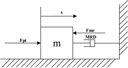
FIGURE 1. Simplified mechanical model of magnetorheological (MR) impact buffer system.
The impact buffer system is characterized by large impact force and extremely short action time. The impact force is adopted in the simulation as shown in Figure 2. As shown in Eq. 2, only when the output damping force
where
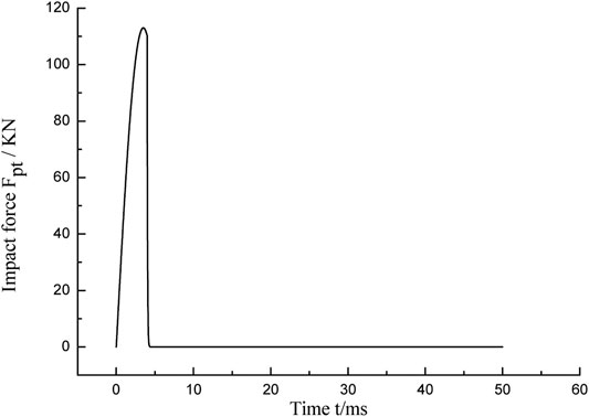
FIGURE 2. Simulated impact signal.
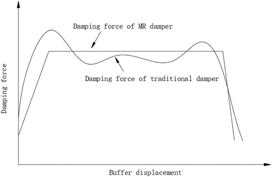
FIGURE 3. Curve of control target.
Assuming that the ideal output damping force of the MR damper is equal to 4,000 N regardless of the influence of temperature on the damping force, the ideal controllable Coulomb damping force of the MR damper
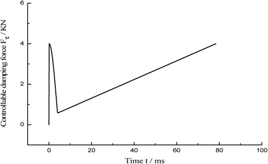
FIGURE 4. Ideal curve of controllable damping force Fτ_i.
However, the dynamic viscosity and the damping force of the MR fluid decrease with the increase in temperature (Wilson et al., 2013). Therefore, the effect of temperature on the damping force must be considered when the MR damper is applied. LORD company’s research (Blanchard, 2003) showed that the viscosity of the MR fluid is in a power exponent relation with the change in temperature; approximately, the viscosity–temperature characteristic of mineral hydraulic oil meets the viscosity–temperature relation, namely,
In this study, the MR fluid used in the damper was produced by Ningbo Shangong Intelligent Safety Technology Co., Ltd. Its model is SG-MRF2035. According to the experimental data of dynamic viscosity and temperature in the manual, the relationship between temperature and dynamic viscosity of the MR fluid can be fitted in MATLAB, the fitting result is shown in Figure 5 and the corresponding equation is as follows:
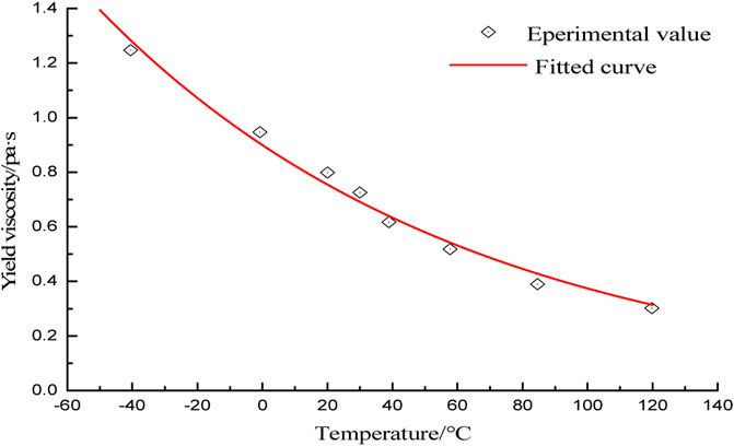
FIGURE 5. Characteristic curve of MR fluid (η ∼ T).
Under the influence of temperature, the damping coefficient
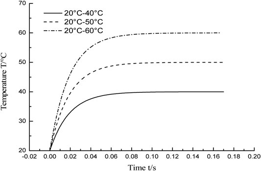
FIGURE 6. Internal temperature simulation curve of MR damper.
It is well known that the ferromagnetic particles in the MR damper cause the hysteresis nonlinearity of the damper, which is manifested as the hysteresis nonlinearity between
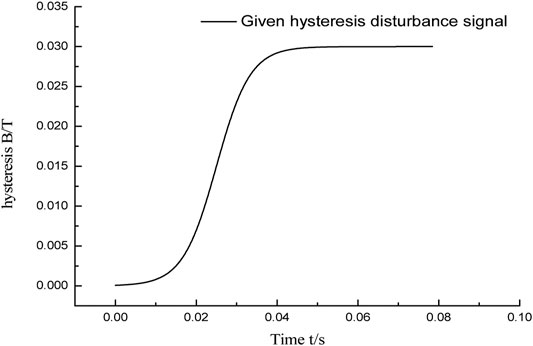
FIGURE 7. Hysteresis curve of MR damper.
According to the MR coil electromagnetic circuit, the theoretical model for the response features of magnetic flux density was established (Li et al., 2018):
where
Considering the internal uncertainty and external disturbance of the system, the system can be rewritten as follows:
where
Let
When the derivative of e is substituted into Eq. 7, the differential equation of the flux density tracking error can be obtained as follows:
The terminal sliding surface is designed as
The CTSMC law is designed as (Wang et al., 2016)
where
Hypothesis 1: Suppose the derivative of
Theorem 1: Suppose the system satisfies Hypothesis 1. Under the control law (Eqs. 11–13), when the gain meets
Proof: According to Eq. 9, the terminal sliding surface (10) can be rewritten as follows:
Substituting Eqs 11–13 into Eq. 15 yields
Taking the Lyapunov equation as
Hence,
It can be proved from the above inequality that if
where
From Eqs. 11–13, it can be seen that the control term
According to the above design process, the control system based on CTSMC is obtained, as shown in Figure 8. The magnetic flux density sliding mode controller is in the dashed box, the input of the sliding mode controller is the error
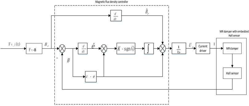
FIGURE 8. Control schematic diagram of MR impact buffer control system based on the CTSMC.
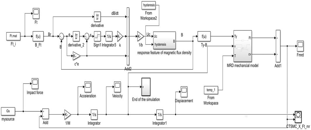
FIGURE 9. Simulation block diagram of MR impact buffer control system containing disturbance based on the CTSMC.
The ESO can estimate the original system state and disturbance together; in addition, the ESO regards internal and external disturbances as the new state of the system. The biggest advantage of the ESO is that it does not rely on the generated disturbance model, nor does it use the functional relationship of the controlled object. The controller can eliminate the system disturbance signal estimated by the ESO, so as to achieve the purpose of auto disturbance rejection (Han, 1998).
where
The second-order linear ESO design of system (21) is as follows:
where
The CTSMC control law not only enables the closed-loop system to have strong antidisturbance ability but also can eliminate buffeting. However, in the case of strong disturbance, the CTSMC control law needs a higher gain to eliminate disturbance. The sliding mode ADRC control method can greatly reduce the CTSMC law gain while compensating the total disturbances of the observation system in real time.
The control law of the sliding mode ADRC is shown in Eqs. 23–25:
where
Hypothesis 2: Suppose the derivative of
where
Theorem 2: Suppose system (7) satisfies Hypothesis 2. In the control law (Eqs. 23–25), the magnetic flux density error of the system will converge to zero in a finite time if the gain satisfies
Proof: According to Eq. 9, the terminal sliding mode surface (10) can be rewritten as
Substituting the control law (Eqs. 23–25) into Eq. 25 yields
Taking the Lyapunov equation as
Hence,
According to Hypothesis 2, the above equation can be rewritten as follows:
The above inequality can prove that if
The block diagram of the sliding mode ADRC system is shown in Figure 10. The input of the controller is the error
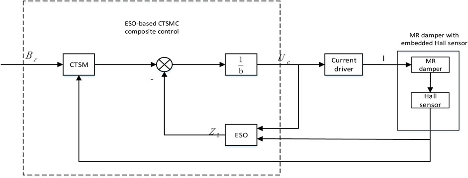
FIGURE 10. Control schematic diagram of the sliding ADRC (CTSMC + ESO).
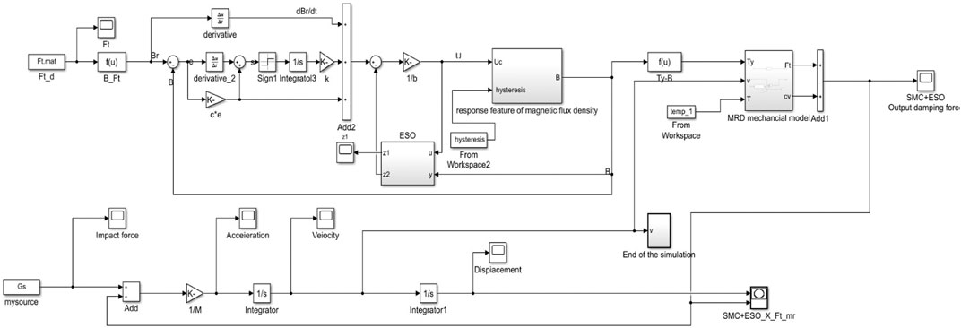
FIGURE 11. Simulation block diagram of MR impact buffer sliding mode ADRC system with disturbances.
The ideal magnetic flux density input signal includes low-frequency signals and high-frequency signals. Among them, the low-frequency signal is a window function and the high-frequency signal includes a high-frequency window function and a multistep function. The maximum amplitude of each analog input signal is set to 1T. Open loop, PID, fractional PID, and CTSMC strategies are adopted to suppress the hysteresis nonlinearity of the MR damper. The simulation results are shown in Figure 13 and Figure 14. In Figure 14, A and C are hysteresis disturbance curves, which are drawn based on the open-loop simulation result that uses the Jiles–Atherton (J–A) model to describe the hysteresis characteristics of the MR damper (Li et al., 2019), as shown in Figure 12. It can be seen from Figure 12A that the hysteresis characteristic of the MR damper in the positive stroke can be ignored, but there is a 30% hysteresis of the reverse stroke in 0.8∼1 s. Therefore, in the simulation in this article, 30% hysteresis is added to the system in 0.8∼1 s of the reverse stroke to form the hysteresis disturbance curve of the window function. As above, the hysteresis curves of the system with the input signals of the high-frequency multistep function and high-frequency window function can be obtained.
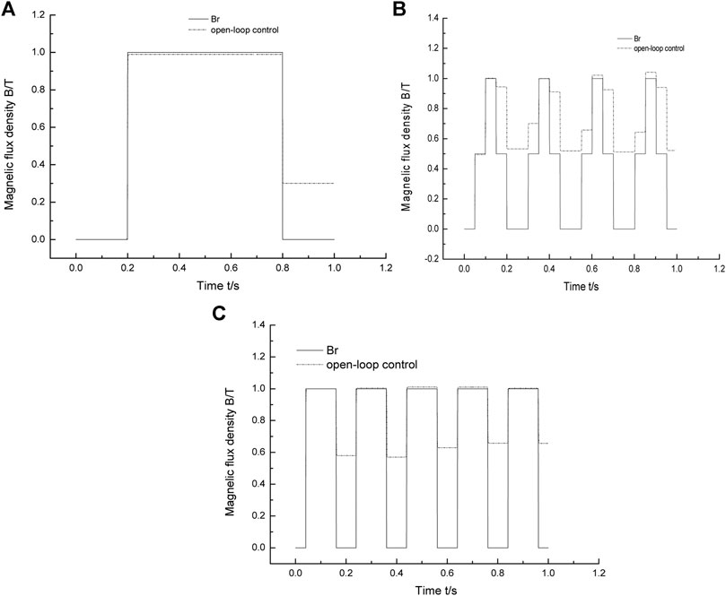
FIGURE 12. Open-loop control response of different high-frequency and low-frequency input signals that uses the J–A model. (A) Window function response using open-loop control. (B) Multistep response using open-loop control. (C) Step response using open-loop control.
According to B and D in Figure 13, after the signal begins to drop in the open-loop control system, the magnetic flux density output by the MR damper cannot track the ideal magnetic flux density. There is a certain amount of hysteresis; at the same time, there is about 20% oscillation at the signal drop point, which seriously affects the control accuracy of the system. In the PID and fractional PID control systems, the changes of the input signal can be tracked by the output signal of the magnetic flux density, but compared with CTSMC, the PID control system has a response time of 0.03 s and 0.7% remaining magnetic, fractional PID control system has 2% overshoot. Compared with the other three control methods, CTSMC has a response time that can almost be neglected and no overshoot in the dynamic process, so that the output can quickly track the input, which shows that compared with the other three control methods, CTSMC has the most obvious suppression effect on hysteresis. The impact loading duration of the MR impact buffer system is very short, always less than 0.1 s. To verify whether the hysteresis suppression control method can work normally in the impact buffer system, two high-frequency input signals were used for simulation. As shown in Figure 14A and C, the origin of the hysteresis curve at high frequency is the same as that at low frequency. The simulation results are shown in Figure 14B and D. Under the condition of high-frequency input signals, the suppression effect of the hysteresis of the four control strategies is not much different from that under low-frequency input signals, which shows that the disturbance suppression control method put forward in this article is suitable for the impact buffer system with a short working cycle and is beneficial for improving the disturbance suppression ability in the MR impact buffer system.
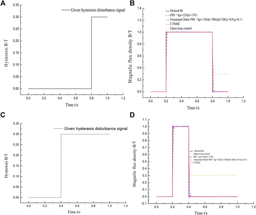
FIGURE 13. Four control responses of different low-frequency input signals. (A) Hysteresis curve. (B) Response of four control multistep functions. (C) Hysteresis curve. (D) Response of four control window functions.
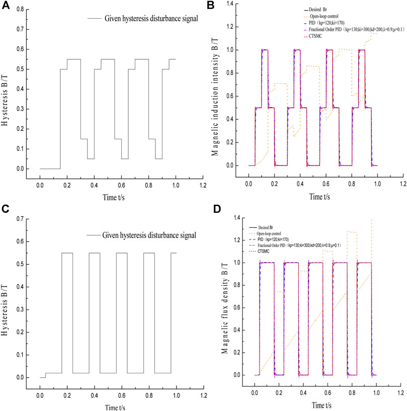
FIGURE 14. Four control responses of different high-frequency input signals. (A) Hysteresis curve. (B) Response of four controlmultistep functions. (C) Hysteresiscurve. (D) Response of four control window functions.
When using an MR damper, the influence of temperature must be considered. As shown in Figure 6, three groups of different temperature disturbance curves are designed, which are 20°C–40°C, 20°C–50°C, and 20°C–60°C. In the case of three groups of different temperature disturbances, the simulation results of the impact buffer system using the CTSMC controller and the CTSMC + ESO controller are shown in Figure 15 and Figure 16. It can be seen from Figure 15 and Figure 16D that the buffering effect of the system is close to the “platform effect” and consistent with the control objective, except for the peak damping force at the beginning. Moreover, the peak damping force output by the MR damper does not change with temperature changes, which indicates that the CTSMC control system and the CTSMC + ESO control system are not sensitive to temperature changes and can effectively suppress the temperature disturbance in the MR shock buffer system.
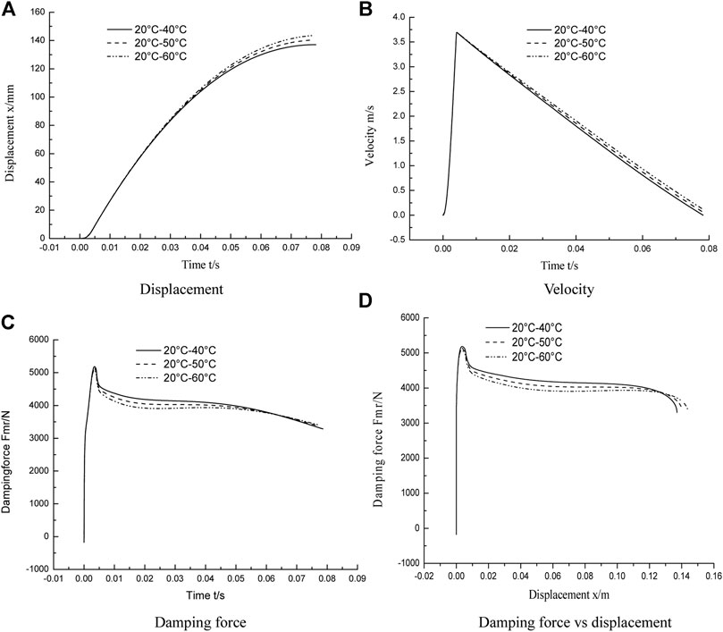
FIGURE 15. Simulation results of MR impact buffer system under CTSMC control strategy. (A) Displacement. (B) Velocity. (C) Damping force. (D) Damping force vs. displacement.
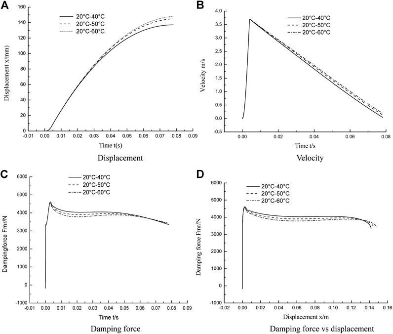
FIGURE 16. Simulation results of MR impact buffer system under CTSMC + ESO control strategy. (A) Displacement. (B) Velocity. (C) Damping force. (D) Damping force vs. displacement.
Under the circumstance of hysteresis disturbance and temperature (20–50°C) disturbance, the simulation results of the MR impact buffer system under the controller of open loop, PID, fractional PID, CTSMC, and the sliding mode ADRC are shown in Figure 17 and Table 1. The standard for evaluating the performance of the MR impact buffer system is that the curve of the output damping force and buffer displacement shows a “platform effect.” In the action stage of the impact force, since the impact force is far greater than the resistance, the energy of the impact load determines the peak value of the speed. As shown in Figure 17B, the speed reaches the peak quickly before 0.005 s, and the peak speed is about 3.7 m/s and then quickly drops to 0. This indicates that the peak speed has nothing to do with the control algorithm and is determined by the energy of the impact load and the structural size of the damper. From the perspective of the output damping force–displacement curve in Figure 17D, it can be seen that the buffering effect under open-loop control is far from the ideal buffering effect during the entire buffering process, and the damping force cannot be maintained as a constant. The damping force–displacement curves under the PID and fractional PID control strategies show that the peak damping force is much larger than the ideal value of 4000 N, and the control effect is close to constant except for the initial part of the buffering process. CTSMC and the sliding mode ADRC method have a better buffering effect, of which the latter is the most satisfactory one. Compared with the other four control algorithms, the sliding mode ADRC algorithm has the smallest initial damping force peak, the “platform effect” between damping force and buffer displacement is more obvious, and the control process is close to a constant. Meanwhile, the buffer displacement of the entire damper system increases significantly, while the output damping force becomes smaller, which is completely consistent with the set control target.
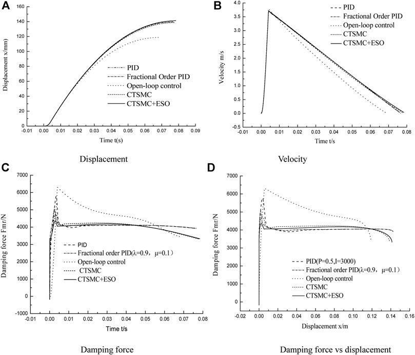
FIGURE 17. Simulation results of MR impact buffer system under five control strategies. (A) Displacement. (B) Velocity. (C) Damping force. (D) Damping force vs. displacement.
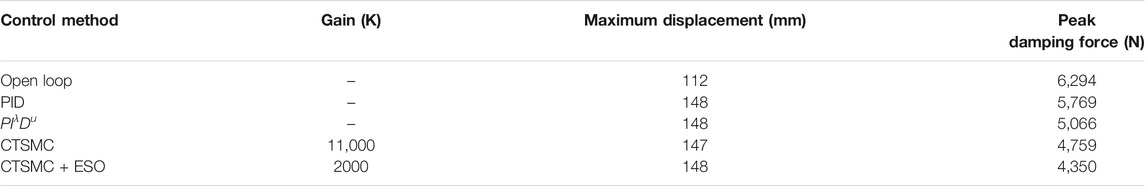
TABLE 1. Comparison of maximum displacement and peak damping force of five control methods.
To facilitate the analysis and comparison of the effects of the five control methods, Table 1 is made. In addition to open-loop control, the displacement of the other control methods is about 148 mm, but the peak value of the output damping force of the sliding mode ADRC algorithm is much smaller than that of the other control algorithms, 1944 N smaller than the maximum output damping force, and the peak damping force is effectively weakened. In addition, compared with CTSMC, the gain of the sliding mode ADRC is 9,000 smaller, which can reduce the pressure of the controller and improve the control accuracy. The simulation results show that disturbance is one of the important reasons for the unsatisfactory buffering effect and further show that the two control strategies proposed in this study have a certain degree of suppression on disturbance during the impact stage. In brief, in the presence of disturbances, compared with other control strategies, the sliding mode ADRC obtains the overall optimal buffering effect, which is consistent with the set control target, and suppresses the influence of temperature and hysteresis disturbances on the shock buffer system and reduces the high gain of the CTSMC law simultaneously.
In this article, the disturbance suppression control method of the MR impact buffer system is studied. First, in order to suppress the influence of disturbance on the MR impact buffer system, the temperature disturbance and hysteresis disturbance of the system are analyzed. Meanwhile, the related disturbance signals are described, and the CTSMC law is proposed. Then, considering that the high gain of the CTSMC control law will cause the steady-state damping force fluctuation of the MR impact buffer system, a sliding mode ADRC is proposed. The Lyapunov stability criterion can ensure the stability of the CTSMC strategy, and the feedforward compensation term based on the ESO disturbance estimation is designed to compensate for the system’s total disturbance to reduce the gain of the CTSMC law and disturbance suppression. Finally, two simulation experiments are carried out in MATLAB/Simulink. One of them uses window function, square wave function, and multistep function as ideal input signals to verify the response time, overshoot, and suppression of hysteresis nonlinearity of the CTSMC method. The second is to establish a simulation model of the MR shock buffer system in MATLAB/Simulink to verify the antidisturbance ability and buffer performance of the system by using the CTSMC method and the sliding mode ADRC method. In order to highlight the advantages of the proposed controllers, an open-loop controller, a PID controller, and a fractional order PID controller are used as a comparison. Numerical simulations show that the CTSMC controller has fast response speed, no overshoot, and effectiveness in restraining the hysteresis of the MR damper. In addition, the simulation results of the MR shock buffer system show that the peak value of the output damping force is the smallest, about 4350 N, when the sliding mode ADRC strategy is adopted in the presence of hysteresis and temperature disturbance; however, the output damping force of the system with the other four control methods is much larger than the ideal value of 4000 N. Furthermore, the gain of the CTSMC can be reduced from 11,000 to 2000 while ensuring better buffer performance. This means that the sliding mode ADRC method proposed in this study is suitable for the MR shock buffer system and can improve the buffer performance of the system under impact load.
The raw data supporting the conclusions of this article will be made available by the authors, without undue reservation.
ZL proposed a sliding mode active disturbance rejection control method and analyzed the experimental data. BW carried out formula derivation and simulation on sliding mode active disturbance rejection control of magnetorheological damper. WW did some work for revising the manuscript and participated in the experiments of this paper.
This work is supported by the National Natural Science Foundation of China (NSFC); grant funded by the Chinese Government (No. 51305207), Youth Science and Technology Innovation Fund of Nanjing Forestry University (grant no. CX2019007) and Natural Science Foundation of Jiangsu Provincial College (Grand No. 17KJB413002).
The authors declare that the research was conducted in the absence of any commercial or financial relationships that could be construed as a potential conflict of interest.
Ahmadian, M., and Norris, J. A. (2008). Experimental analysis of magnetorheological dampers when subjected to impact and shock loading. Communications in Nonlinear Science and Numerical Simulation 13, 1978–1985. doi:10.1016/j.cnsns.2007.03.028
Ahmadian, M., and Poynor, J. C. (2001). An Evaluation of Magneto Rheological Dampers for Controlling Gun Recoil Dynamics. Shock and Vibration 8, 147–155. doi:10.1155/2001/674830
Alonge, F., Cirrincione, M., D'Ippolito, F., Pucci, M., and Sferlazza, A. (2017). Robust Active Disturbance Rejection Control of Induction Motor Systems Based on Additional Sliding-Mode Component. IEEE Trans. Ind. Electron. 64, 5608–5621. doi:10.1109/TIE.2017.2677298
Bai, X.-X., Shen, S., Wereley, N. M., and Wang, D.-H. (2019). Controllability of magnetorheological shock absorber: I. Insights, modeling and simulation. Smart Mater. Struct. 28, 015022. doi:10.1088/1361-665X/aaf072
Bai, X.-X., Wereley, N. M., Hu, W., and Wang, D.-H. (2012). Mechanics and Behavior of Active Materials; Integrated System Design and Implementation; Bio-Inspired Materials and Systems; Energy Harvesting (Stone Mountain, Volume 2. Georgia, USA: American Society of Mechanical Engineers), 485–495. doi:10.1115/SMASIS2012-8250A Bidirectional-Controllable Magnetorheological Energy Absorber for Shock and Vibration Isolation Systems
Batterbee, D., and Sims, N. D. (2009). Temperature Sensitive Controller Performance of MR Dampers. Journal of Intelligent Material Systems and Structures 20, 297–309. doi:10.1177/1045389X08093824
Blanchard, E. D. (2003). On the Control Aspect of Semiactive Suspensions for Automobile Applications.
Browne, A. L., Mccleary, J. D., Namuduri, C. S., and Webb, S. R. (2009). Impact Performance of Magnetorheological Fluids. Journal of Intelligent Material Systems and Structures 20, 723–728. doi:10.1177/1045389X08096358
Carlson, J. D. (2002). WHAT MAKES A GOOD MR FLUID?. Journal of Intelligent Material Systems and Structures 13, 431–435. doi:10.1106/104538902028221
Choi, Y.-T., and Wereley, N. M. (2005). Mitigation of biodynamic response to vibratory and blast-induced shock loads using magnetorheological seat suspensions. Proceedings of the Institution of Mechanical Engineers, Part D: Journal of Automobile Engineering 219, 741–753. doi:10.1243/095440705x28330
Choi, Y.-T., and Wereley, N. M. (2003). Vibration Control of a Landing Gear System Featuring Electrorheological/Magnetorheological Fluids. Journal of Aircraft 40, 432–439. doi:10.2514/2.3138
Choi, Y.-T., and Wereley, N. M. (2015). Drop-Induced Shock Mitigation Using Adaptive Magnetorheological Energy Absorbers Incorporating a Time Lag. J. Vib. Acoust. 137, 011010. doi:10.1115/1.4028747
Dong, X.-m., Yu, M., Liao, C.-r., and Chen, W.-m. (2010). Comparative research on semi-active control strategies for magneto-rheological suspension. Nonlinear Dyn 59, 433–453. doi:10.1007/s11071-009-9550-8
Dong, X., Yu, M., and Zhu, L. (2011). Electro-Rheological Fluids and Magneto-Rheological Suspensions. Philadelphia, USA: WORLD SCIENTIFIC), 186–192. doi:10.1142/9789814340236_0026 RESEARCH ON MAGNETORHEOLOGICAL ELASTOMER ABSORBER AND ITS IMPACT TEST
Du, X., Yu, M., Fu, J., and Huang, C. (2020). Experimental study on shock control of a vehicle semi-active suspension with magneto-rheological damper. Smart Mater. Struct. 29, 074002. doi:10.1088/1361-665X/ab859e
Goncalves, F. D., Ahmadian, M., and Carlson, J. D. (2006). Investigating the magnetorheological effect at high flow velocities. Smart Mater. Struct. 15, 75–85. doi:10.1088/0964-1726/15/1/036
Gordaninejad, F., and Breese, D. G. (1999). Heating of magnetorheological fluid dampers. Journal of Intelligent Material Systems and Structures 10, 634–645. doi:10.1106/55d1-xaxp-yfh6-b2fb
Guo, Y.-Q., Xie, W.-H., and Jing, X. (2019). Study on Structures Incorporated With MR Damping Material Based on PSO Algorithm. Front. Mater. 6, 37. doi:10.3389/fmats.2019.00037
Huang, T., Huang, D., Wang, Z., Dai, X., and Shah, A. (2020). Generic Adaptive Sliding Mode Control for a Quadrotor UAV System Subject to Severe Parametric Uncertainties and Fully Unknown External Disturbance. Int. J. Control Autom. Syst. 19, 698–711. doi:10.1007/s12555-019-0853-3
Hughes, J. E., Kim, Y., El-Korchi, T., and Cyganski, D. (2017). Radar-based impact load prediction for damage mitigation of infrastructure. Journal of Vibration and Control 23, 1908–1924. doi:10.1177/1077546315603856
Lai, Z., LIU, X., GENG, J., and LI, L. (2011). Sliding mode control of hysteresis of piezoceramic actuator based on inverse Preisach compensation. Opt. Precis. Eng. 19, 1281–1290. doi:10.3788/OPE.20111906.1281
Li, Z. C., and Wang, J. (2012). A gun recoil system employing a magnetorheological fluid damper. Smart Mater. Struct. 21, 105003. doi:10.1088/0964-1726/21/10/105003
Li, Z., Gong, Y., Li, S., and Wang, W. (2019). Magnetic Hysteresis Compensation Control of a Magnetorheological Damper. Front. Mater. 6, 299. doi:10.3389/fmats.2019.00299
Li, Z., GU, Q., ZHOU, B., and WANG, J. (2018). Modeling and tests for response features of MR damper as a shock isolation device. J. Vib. SHOCK 37, 163–168+187.
Liu, Y., Gordaninejad, F., Evrensel, C. A., Wang, X., and Hitchcock, G. (2005). Comparative Study on Vibration Control of a Scaled Bridge Using Fail-Safe Magneto-Rheological Fluid Dampers. J. Struct. Eng. 131, 743–751. doi:10.1061/(ASCE)0733-944510.1061/(asce)0733-9445(2005)131:5(743)20051315743
McKee, M., Wang, X., and Gordaninejad, F. (2011). ASME 2011 Conference on Smart Materials, Adaptive Structures and Intelligent Systems, Volume 1. Arizona, USA: ScottsdaleASMEDC), 603–612. doi:10.1115/SMASIS2011-5127Behavior of a Compressible Magnetorheological Fluid Damper at High Temperatures
Meng, Z., Ren, W., and You, Z. (2010). Distributed finite-time attitude containment control for multiple rigid bodies. Automatica 46, 2092–2099. doi:10.1016/j.automatica.2010.09.005
Ouyang, Q., Zheng, J., Li, Z., Hu, M., and Wang, J. (2016). Controllability analysis and testing of a novel magnetorheological absorber for field gun recoil mitigation. Smart Mater. Struct. 25, 115041. doi:10.1088/0964-1726/25/11/115041
Pan, Z., Wang, W., Song, S., and Lu, K. (2016). Nonlinear Attitude Control of Tiltrotor Aircraft Based on Active Disturbance Rejection Sliding Mode Method. in Nanjing, PEOPLES R CHINA, 1351–1356.
Rahmat, M. S., Hudha, K., Kadir, Z. A., Nuri, N. R. M., Amer, N. H., and Abdullah, S. (2019). Comparison of Control Strategy on Magneto-Rheological Fluid Damper Performance for Impact Reduction. IOP Conf. Ser.: Mater. Sci. Eng. 530, 012032. doi:10.1088/1757-899X/530/1/012032
Shou, M., Liao, C., Zhang, H., Li, Z., and Xie, L. (2018). Modeling and testing of magnetorheological energy absorbers considering inertia effect with non-averaged acceleration under impact conditions. Smart Mater. Struct. 27, 115028. doi:10.1088/1361-665X/aae6a0
Tan, C. P., Yu, X., and Man, Z. (2010). Terminal sliding mode observers for a class of nonlinear systems. Automatica 46, 1401–1404. doi:10.1016/j.automatica.2010.05.010
Tudon-Martinez, J. C., Hernandez-Alcantara, D., Amezquita-Brooks, L., Morales-Menendez, R., Lozoya-Santos, J. d. J., and Aquines, O. (2019). Magneto-rheological dampers-model influence on the semi-active suspension performance. Smart Mater. Struct. 28, 105030. doi:10.1088/1361-665X/ab39f2
Wang, H., Li, S., Lan, Q., Zhao, Z., and Zhou, X. (2016). Continuous terminal sliding mode control with extended state observer for PMSM speed regulation system. Trans. Inst. Meas. Control 10.
Wang, H., Li, X., Liu, X., Karkoub, M., and Zhou, L. (2020). Fuzzy Sliding Mode Active Disturbance Rejection Control of an Autonomous Underwater Vehicle-Manipulator System. J. Ocean Univ. China 19, 1081–1093. doi:10.1007/s11802-020-4250-6
Wang, J., Zhu, C., Yang, Z., and Huang, L. (In Press). Control Algorithm Study of Magneto-rheological Damper under Impact Load.
Wang, X. (2018). Observer Based Force Estimation of Magnetorheological Damper Subjective to Unertainties and Faults. Comput. Simul. 35.
Wang, X., Liu, J., and Cai, K.-Y. (2010). Tracking control for VTOL aircraft with disabled IMUs. International Journal of Systems Science 41, 1231–1239. doi:10.1080/00207720903244048
Wereley, N. M., Choi, Y.-T., and Singh, H. J. (2011). Adaptive Energy Absorbers for Drop-induced Shock Mitigation. Journal of Intelligent Material Systems and Structures 22, 515–519. doi:10.1177/1045389X10393767
Wilson, N. L., Wereley, N. M., Hu, W., and Hiemenz, G. J. (2013). Analysis of a magnetorheological damper incorporating temperature dependence. Ijvd 63, 137. doi:10.1504/IJVD.2013.056102
Xia, F., Zhu, W., and Wei, M. (2020). Analysis of Influence of Temperature on Performance of Magnetorheological Fluid Dampers. Noise Vib. Control 40, 253–258.
Yoon, J.-Y., Kang, B.-H., Kim, J.-H., and Choi, S.-B. (2020). New control logic based on mechanical energy conservation for aircraft landing gear system with magnetorheological dampers. Smart Mater. Struct. 29, 084003. doi:10.1088/1361-665X/ab9e11
Yuan, X., Tian, T., Ling, H., Qiu, T., and He, H. (2019). A Review on Structural Development of Magnetorheological Fluid Damper. Shock and Vibration 2019, 1–33. doi:10.1155/2019/14989622019
Keywords: MR fluid damper, disturbance, continuous terminal sliding mode, active disturbance rejection control, shock buffer system
Citation: Wang B, Wang W and Li Z (2021) Sliding Mode Active Disturbance Rejection Control for Magnetorheological Impact Buffer System. Front. Mater. 8:682215. doi: 10.3389/fmats.2021.682215
Received: 18 March 2021; Accepted: 11 May 2021;
Published: 01 June 2021.
Edited by:
Yancheng Li, University of Technology Sydney, AustraliaReviewed by:
Huixing Wang, Nanjing University of Science and Technology, ChinaCopyright © 2021 Wang, Wang and Li. This is an open-access article distributed under the terms of the Creative Commons Attribution License (CC BY). The use, distribution or reproduction in other forums is permitted, provided the original author(s) and the copyright owner(s) are credited and that the original publication in this journal is cited, in accordance with accepted academic practice. No use, distribution or reproduction is permitted which does not comply with these terms.
*Correspondence: Zhaochun Li, bHpjLmhuQDE2My5jb20=
Disclaimer: All claims expressed in this article are solely those of the authors and do not necessarily represent those of their affiliated organizations, or those of the publisher, the editors and the reviewers. Any product that may be evaluated in this article or claim that may be made by its manufacturer is not guaranteed or endorsed by the publisher.
Research integrity at Frontiers
Learn more about the work of our research integrity team to safeguard the quality of each article we publish.