 Peishuai Chen1,2,3
 Jiacheng Li
 Minghua Huang
- 1School of Highway, Chang'an University, Xi'an, China
- 2China Communications Construction Company (CCCC) Second Harbour Engineering Company Ltd., Wuhan, China
- 3Key Laboratory of Large-Span Bridge Construction Technology, CCCC Second Harbour Engineering Company LTD, Wuhan, China
- 4Research and Development Center of Transport Industry of Intelligent Manufacturing Technologies of Transport Infrastructure, Wuhan, China
- 5Key Laboratory of Building Safety and Energy Efficiency of the Ministry of Education, Hunan University, Changsha, China
In geotechnical engineering, vertical drainage is the most economical method for accelerating the consolidation of a large area of soft ground. In this study, we analyze the viscoelasticity of the soil and the actual drainage conditions on the top surface of the soil, and then we introduce continuous drainage boundary conditions and adopt a fractional derivative model to describe the viscoelasticity of the soil. With the use of a viscoelasticity model, the governing partial differential equation for vertical drains under continuous drainage boundary conditions is obtained. With the application of the Crump numerical inversion method, the consolidation solution for vertical drains is also obtained. Further, the rationality of the proposed solution is verified by several examples. Moreover, some examples are provided to discuss the influence of interface drainage parameters on the top surface of soil and the viscoelasticity parameters of soil on the consolidation behavior of vertical drains. The proposed method can be applied in the fields of transport engineering to predict the consolidation settlement of a foundation reinforced by vertical drains.
Introduction
Consolidation of vertical drains is the most economical and effective method for reinforcement treatment of a large area of soft soil (Indraratna et al., 2010, 2012). In order to theoretically study the consolidation of vertical drains, Carrillo (1942) first proposed the division of a combination of seepage problems in vertical drains into radial seepage and vertical seepage for separate analysis. Subsequently, Barron (1942), Horne (1964), Yoshikuni and Nakanodo (1974), Yoshikuni (1979), and Xie et al. (1993) divided the vertical drain consolidation problem into two ideal conditions, free strain and equal strain, to analyze and answer the problems separately. They established a linear elastic consolidation theory for vertical drains. However, a large amount of scientific research and engineering measurement data has shown that soil has viscoelasticity properties and that its consolidation process cannot be completed in a short time. The soil consolidation process often takes years or even decades to complete (Karlsson et al., 2016). For the purpose of analyzing viscoelastic soil, many scholars have introduced viscoelasticity models into the consolidation theory of vertical drains, such as the classic Kelvin, Maxwell, Merchant and the generalized Kelvin. Zhao (1988) and Liu et al. (1998, 2005) established the consolidation differential equation for integer-order viscoelastic vertical drains and obtained numerous excellent results.
In 1940, Blair (1947) and Gerasimov (1948) proposed a fractional derivative model to describe viscoelasticity behaviors of a linear elasticity model and an integer-order viscoelasticity model. Bagley and Torvik (1986, 2012) verified the rationality of a fractional derivative rheological model by combining a molecular theory with a rheological theory based on fractional derivatives. Subsequently, the fractional derivative viscoelasticity model began to appear in geotechnical engineering. Sun and Wei (2007) and Li-jun et al. (2011) studied the creep of soft soil with a fractional calculus model. Wang et al. (2017) used the fractional derivative model to describe the 1D consolidation of viscoelastic soil. Qing-zi et al. (2016) experimentally verified that the application of the fractional derivative model is effective in describing creep deformation of soft soils. Huang and Li (2019) studied the consolidation characteristics of fractional derivative viscoelastic vertical drains for variable loads based on the fractional-derivative Merchant (FM) model. Because of the studies mentioned above, the fractional derivative model will be used more frequently in the study of vertical drains consolidation in the future.
Traditional boundary conditions are mainly Terzaghi (1943) drainage (permeab le and impervious). Gray (1945) proposed a semi-permeable boundary. Schiffmann and Stein (1970) studied the effect of permeability coefficient on the 1D consolidation of soil. However, the Terzaghi drainage boundary has nothing to do with time, and the boundary conditions contradict the initial conditions. Although the semi-permeable boundary reflects the change process in the permeable boundary, its boundary condition is a function that complicates the solution process. Based on this, Mei et al. (2013) proposed a continuous drainage boundary that was simple in form and could reflect changes in drainage boundary pore pressure with time to describe the actual boundary drainage during soil consolidation.
This study is conducted based on the research results mentioned above and on the FM model. We have introduced the continuous drainage boundary conditions proposed by Mei and have derived a solution to the fractional derivative viscoelastic vertical drain consolidation problem for continuous drainage boundary conditions. Finally, some special cases are given to study the effect of interface drainage parameters and soil fractional viscoelasticity parameters on consolidation properties.
Model and Boundary Conditions
Continuous Drainage Boundary
According to Mei et al. (2013), the expression of the continuous drainage boundary is
where q0 is the initial load and b is the interface drainage parameter, which can be obtained through experiments. t is the time.
From Equation (1), it can be easily found that when t → 0, the pore-water pressure on the top surface of soil results in u(0, 0) = q0, satisfying the initial condition. When t → ∞, the pore-water pressure on the top surface of soil approaches 0. Therefore, Equation (1) solves the initial condition problem, and it reflects the change in pore pressure at the boundary of soil with time.
Consolidation Model of Vertical Drains
In order to facilitate mathematical derivation, the following basic assumptions are adopted in this study, as shown below:
(1) Darcy's law applies to seepage of water in soil.
(2) The amount of inflowing water from soil at any depth is equivalent to the amount of outflowing water in vertical drains.
(3) External load is infinite and evenly distributed.
(4) Equal strain condition is established; that is, the soil and the vertical drains at the same depth only undergo vertical deformation, and the vertical deformation is equal.
(5) The compressibility of smeared area is the same as the compressibility of undisturbed soil.
(6) Permeability coefficients in the vertical direction of the smeared area are equal to those of the undisturbed soil, and the horizontal permeability coefficient of the smeared area is less than that of the undisturbed soil.
The consolidation system is composed of vertical drains, smeared area, and natural soil, as shown in Figure 1. From the figure, q0 is the pre-compression load on the top surface of the soil. rw, rs, and re are vertical drains radius, smear area radius, and influence radius, respectively. r and z are the radial and vertical coordinates, respectively. kv is the vertical permeability coefficient of the soil in the smeared area and the natural area. ks and kh are the horizontal permeability coefficient of the smeared soil and the natural soil, respectively. kw is the vertical permeability of the vertical drains. γw is the average severity of water. εv is the strain of soil in vertical direction. us(r, z, t) is the excess pore-water pressure in the smeared area. un(r, z, t) is the excess pore-water pressure in the natural soil. ū(z, t) is the average pore-water pressure in the soil. uw(z, t) is the pore-water pressure in the vertical drains. h is the thickness of the soil.
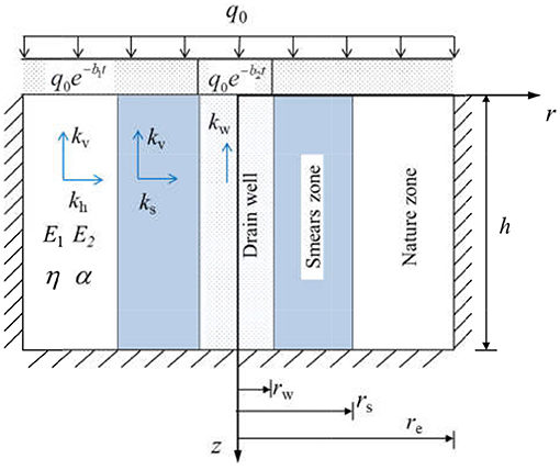
Figure 1. The consolidation system of vertical drains under continuous drainage boundary conditions.
Based on the above assumptions, the basic equation for vertical drain consolidation is as follows (Barron, 1942; Tang and Onitsuka, 2000):
The average pore-water pressure of the soil can be expressed as follows:
The top boundary in this model is considered to continuous drainage and the bottom boundary is considered to be undrained. At the same time, according to symmetry, no seepage occurs at the boundary of the soil-affected area. Thus, boundary conditions are as follows:
where b1 and b2 represent the interface drainage parameters on the top surface of the soil outside the vertical drains and the interface drainage parameters on the top surface of the vertical drains, respectively. Initial conditions of the consolidation model are as follows:
Fractional Derivative Model
In order to determine the rheological consolidation properties of vertical drains more accurately, the theory of vertical drain consolidation adopted the FM model (Huang and Li, 2019), as shown in Figure 2.
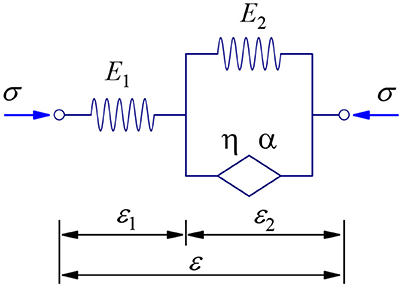
Figure 2. Fractional derivative Merchant (FM) model.
The constitutive equations for the FM model can be expressed as
where σ is the total stress, ε is the total strain, E1 is the elastic modulus of spring 1, E2 is the elastic modulus of spring 2, λ = η/E2 is the viscosity coefficient of the bomb element, ε1 and ε2 are strain of spring 1 and strain of spring 2, respectively, and is the fractional-derivative operator of type α of function f(t), which is defined as
where f(t) is a function, α is the fractional order, 0 ≤ α ≤ 1. Γ(·) is the gamma function, and τ is an integral variable.
The Laplace transform for Equation (9) can be obtained as follows:
This study introduces the FM model to describe the effective stress-strain relationship in the soil. Using the effective stress principle, the effective stress of soil under loading is
Obviously, the initial conditions of the soil are
By substituting Equation (12) into Equation (11) and performing the inverse Laplace transform on Equation (11), the expression changes as follows:
where ⊗ denotes convolution. Furthermore,
where δ(t) is the Dirac function. When α = 1, the FM model degenerates to a standard Merchant (SM) model. When α = 0, the FM model degenerates to a linear elasticity model.
Derivation and Solution
Governing Equations and Solutions
The consolidation differential Equation of the fractional viscoelastic vertical drains for continuous drainage boundary conditions is the same as the derivation Equation of (Huang and Li, 2019):
where cv = kvE1/γw, ch = khE1/γw, and n(=re /rw) represents the ratio of vertical drains radius to influence radius, and Eα,α(t) is a Mittag–Leffler function.
The following dimensionless parameters and variables are defined as
Substituting the above parameters and variables into Equations (16) and (17) results in
The continuous drainage initial conditions and boundary conditions can be rewritten as
Since the continuous drainage boundary conditions are non-homogeneous, the finite Fourier sine transform is very suitable for solving such a problem. The expression of the finite Fourier sine transform of f(x) is (Sneddon, 1995).
where 0 ≤ z ≤ l. The inverse transformation is defined as
The above finite Fourier sine transform has the following basic properties:
In order to facilitate the application of finite Fourier sine transform, we applied the principle of mirroring and found that the consolidation problem under the conditions of the single drainage boundary with soil thickness of h is equivalent to the problem in a double sided continuous drainage boundary with soil thickness of 2h. The problem in the double-sided continuous drainage boundary is shown in Figure 3.
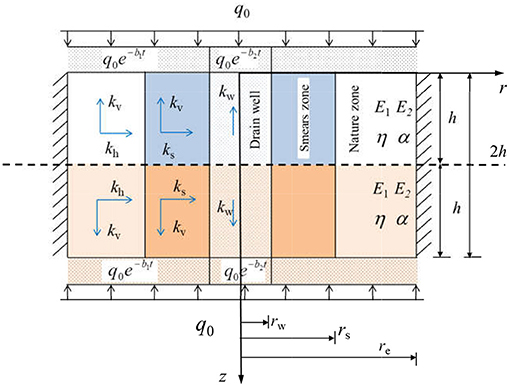
Figure 3. Schematic of the equivalent consolidation model of vertical drains.
The bottom boundary conditions of the equivalent consolidation model are the same as top boundary conditions, which are
Dimensionless initial conditions and the boundary of the equivalent consolidation model of vertical drains are
where and are the dimensionless interface drainage parameters on the top surface of the foundation soil outside the vertical drains and the dimensionless interface drainage parameters on the top surface of the vertical drains, respectively.
Substituting Equations (27) and (28) into Equation (19) leads to
Implementing the Laplace transform of Tv for Equation (18) and using the given initial condition of Equation (29) generate
Correspondingly, the boundary conditions of Equations (27) and (28) can be transformed into
Performing the finite Fourier sine transform on ṽw(ξ, p) results in
where M = mπ/2m = 1, 2, ⋯. The inverse transformation of Equation (34) is
The basic properties of the finite Fourier sine transform are
The finite Fourier sine transform is performed on both ends of Equation (31), and Equations (32) are used to obtain the following:
where . By solving Ṽm in Equation (37), the expression of Ṽm can be obtained by,
where
Performing the inverse Laplace transform on Ṽm results in
Performing the inverse finite Fourier sine transform on Equation (40) leads to the solution for pore-water pressure in the vertical drains, which is
where Tm is the inverse Laplace transform of .
where , and β is a real number. Generally, for the case of 0 < α < 1, Equation (44) is difficult to have an analytical solution. The Laplace transform numerical inversion Crump method (Crump, 1976; Koeller, 1984) is used to obtain the solution for Tm, which is
where T is a real parameter exceeding one-half of the longest time.
By substituting Equation (41) into Equation (19), the average pore-water pressure of the soil layer can be obtained as
Based on Equation (44), the average degree of consolidation U can be obtained as
Solution Validation
Degeneration to the Terzaghi Drainage Boundary
In this section, the rationality of the consolidation solution derived from this study is verified by comparison with two existing theories. The first case involves the degeneration of the solution in this study to the consolidation solution for the Terzaghi drainage boundary condition (i.e., c1 → ∞, c2 → ∞). After degeneration, Equation (42) can be simplified to
Based on Equation (45), the following expression can be obtained:
Obviously, the degradation solution in this study is exactly the same as that in the result obtained by Huang and Li (2019) based on the fractional derivative viscoelastic vertical drain consolidation model for the completely pervious boundary condition. As shown in Figure 4A, the calculation result of the solution in Huang and Li (2019) is consistent with the calculation result of the solution in this study.
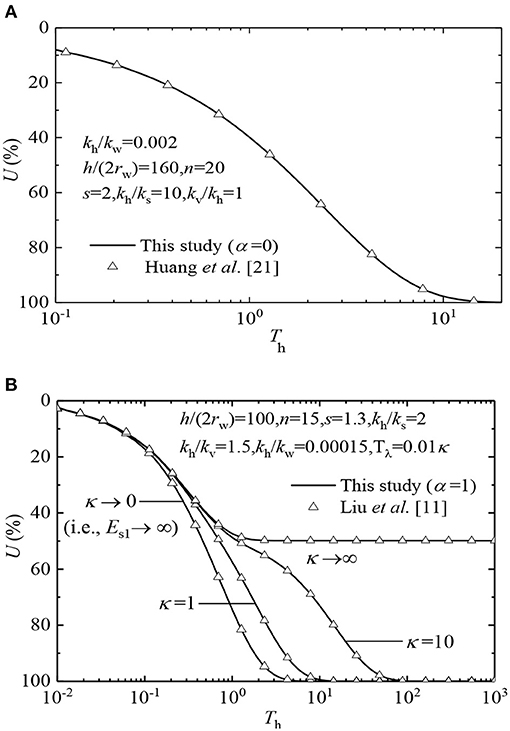
Figure 4. Results of the comparison of U-curve: (A) degeneration to the Terzaghi drainage boundary; (B) degeneration to the SM model.
Degeneration to SM Model
In the second case, the solution in this study is degenerated into the solution with the SM model for the completely pervious boundary (i.e., c1 → ∞, c2 → ∞, α = 1) and compared with the consolidation solution of Liu et al. (1998), which is based on the integer-order viscoelasticity model for vertical drains. In order to facilitate the comparison, it is assumed that the parameters of the vertical drains are the same as those in the study of Liu et al. (1998). The calculation parameters are h/(2rw) = 100, n = 15, s = 1.3, kh/ks = 2, kh/kv = 1.5, kh/kw = 0.00015, and Tλ = 0.01κ. κ is changed from 0 to ∞. The time parameter is
where Th is the same as that given by Liu et al. (1998).
From Figure 4B, it can be observed that the consolidation solution in this study degenerates into an integer-order viscoelasticity model for a completely pervious boundary, which is the same as the U-curve calculated by Liu et al. (1998). Therefore, the solution derived in this study is consistent with the existing theory.
Parameter Analysis
From the deduced fractional-derivative viscoelastic vertical drain consolidation solution, it can be easily found that the consolidation characteristics are related to the interface drainage parameters on the top surface of the soil outside vertical drains c1 and at the top of vertical drains c2. In addition, the viscoelastic parameters of the soil also affect soil consolidation. This study describes the compilation of the program based on the solution mentioned above, mainly calculation and analysis of the parameters c1, c2, α, κ, and Tλ, and discusses the general law of the consolidation characteristics of fractional derivative viscoelastic vertical drains. In the calculation, the design parameters of the vertical drains are consistent with those given in Huang and Li (2019) and are as follows: h/(2rw) = 100, n = 15, s = 1.3, kh/ks = 2, kh /kv = 1.5, kh/kw = 0.00015, Tλ = 0.1, κ = 10, and α = 0.5.
Analysis of Interface Drainage Parameters
Figure 5 shows the influence of equivalent change in the drainage parameters of the soil top surface interface inside and outside the vertical drains on the U-curves. Figure 6 illustrates the impact of interface drainage parameters on the top surface of the soil outside vertical drains c1 on the U-curves when interface drainage parameters at the top of vertical drains c2 remain constant. Figure 7 depicts the impact of the interface drainage parameters c2 on U-curves when the interface drainage parameters c1 remain constant. It can be seen from Figures 5–7 that the change in the interface drainage parameters has a crucial impact on U-curves. The pore-water pressure of different interface drainage parameters dissipates differently with time. The greater the interface drainage parameter, the faster the dissipation of the excess pore water pressure. When the interface drainage parameter is increased to 104, the U-curve approaches a curve. This indicates that when the interface drainage parameter is >104, the drainage boundary approaches the complete drainage boundary. Therefore, the continuous drainage boundary can describe the drainage boundary between the completely drained boundary and the completely undrained boundary, which is more in line with engineering reality.
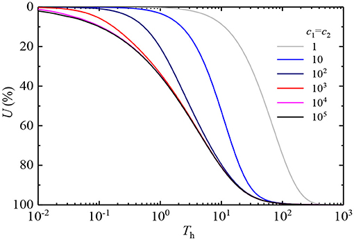
Figure 5. Consolidation progress with different interface drainage parameters.
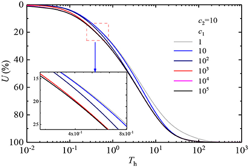
Figure 6. Consolidation progress with different values of c1.
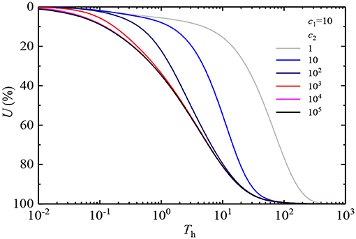
Figure 7. Consolidation progress with different values of c2.
Figure 8 shows the distribution curve of the pore-water pressure vw in the vertical drains and the average pore-water pressure along the depth range when the interface drainage parameters c1 and c2 change equivalently. From the figure, it can be observed that under the same consolidation time, vw and both decrease with the increase in the interface drainage parameters of the soil. When the interface drainage parameters are the same, as the consolidation time increases from Th = 1 to Th = 10, the pore-water pressure gradually dissipates.
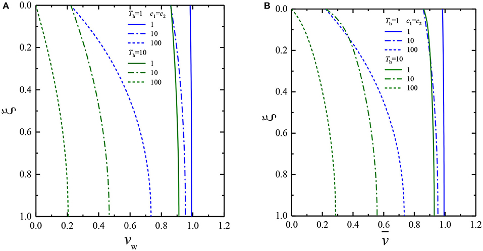
Figure 8. Dissipation of pore-water pressure at any depth when c1 = c2: (A) pore pressure in vertical drains, (B) average pore pressure in the soil layer.
Figure 9 shows the distribution curves of vw and along the depth range when the interface drainage parameters c2 remain unchanged and the interface drainage parameters c1 changes. As shown in Figure 9B, it is clearly seen that the dissipation of is affected by the interface drainage parameters c1. However, after a certain depth, is no longer affected by the interface drainage parameters c1. Moreover, vw relative to is less affected by the interface drainage parameters c1.
Figure 9. Dissipation of pore-water pressure at any depth when c2 = 10 and c1 changes: (A) pore pressure in the vertical drains, (B) average pore pressure in the soil layer.
Figure 10 shows the distribution curves of vw and along the depth range when the interface drainage parameters c1 remain constant and the interface drainage parameters c2 changes. Figure 10 shows the significant effect of the interface drainage parameters c2 on pore-water pressures vw and . Furthermore, in the initial stage, the pore-water pressure vw in the vertical drains is more affected by the interface drainage parameters c2 than the average pore-water pressure .
Figure 10. Dissipation of pore-water pressure at any depth when c1 =10 and c2 changes: (A) pore pressure in the vertical drains, (B) average pore pressure in the soil layer.
Analysis of Fractional Viscoelasticity Parameters
Figure 11 illustrates the effect of the fractional order α on U-curves. In this figure, the other parameters remain unchanged except for the fractional order α. Obviously, Figure 11 shows that in the initial stage, U-curves are very close in value, indicating that pore water pressure is not sensitive to fractional order α. However, in the later stage, the lesser the fractional orderα, the earlier soil consolidation completed, revealing that α has a great impact on the dissipation rate of pore-water pressure. This phenomenon is caused by the fractional derivative element. In the later stage of consolidation, when α = 0, the soil is a linear elastic body, and the consolidation speed is fast; when α gradually increases to 1, the soil becomes more viscous; and the effective stress increases slowly, which causes the pore-water pressure to dissipate more slowly.
Figure 11. Consolidation process with different values of α.
Figure 12 illustrates the effect of the modulus ratio κ on U-curves. In this figure, the other parameters remain unchanged except for κ. Since the modulus E1 of the independent spring is set to 1, the influence of the independent spring modulus E1 is eliminated; and the influence of spring 2 is reflected independently. Obviously, the figure shows that the average degree of consolidation decreases when the soil layer modulus ratio increases.
Figure 12. Consolidation process with different values of κ.
Figure 13 illustrates the effect of the creep time factor Tλ on U-curves. In this figure, the other parameters remain unchanged except for Tλ. The creep time factor is , which is related to the viscosity coefficient of the soil. From the figure, it is clearly seen that in the early stage, the greater Tλ is the faster excess pore-water pressure dissipates. However, in the late stage, the greater Tλ, the slower the dissipation rate of the pore-water pressure. This phenomenon is in a good agreement with the 1D consolidation of viscoelastic soil (Xie et al., 2008).
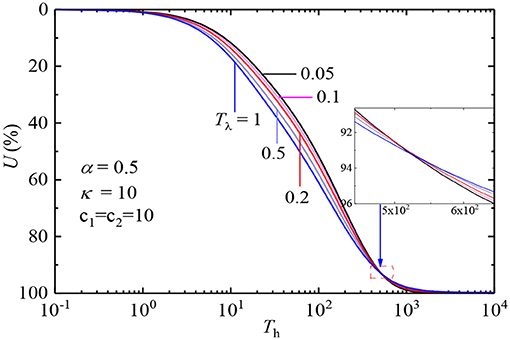
Figure 13. Consolidation process with different values of Tλ.
Conclusions
This study combined continuous drainage boundary conditions and the fractional-derivative model to establish the governing differential equations of vertical drains. After a series of derivation, the consolidated solution was obtained, and the accuracy of the solution was verified by comparison with existing theories. Finally, the solution is used to study the effect of the parameters of interface drainage and viscoelasticity on the behavior of consolidation. Some important conclusions are summarized as follows:
(1) Continuous drainage boundary can describe the change in pore-water pressure at the boundary of soil with time. In addition, the greater the interface drainage parameter, the faster the pore-water pressure dissipates. When the interface drainage parameter is >104, the drainage boundary approaches the complete drainage boundary.
(2) The interface drainage parameters on the top surface of the soil at the boundary outside the vertical drains mainly affect the dissipation rate of average pore-water pressure in the soil layer, when other parameters remain consistent. On the other hand, the interface drainage parameters on the top surface of the vertical drains mainly influence the dissipation rate of the pore-water pressure in the vertical drains, when other parameters remain consistent.
(3) Fractional order is a crucial factor affecting the consolidation of viscoelastic vertical drains. In the later stage of consolidation, the greater the fractional order, the more viscous the soil and the slower the progress of soil consolidation.
(4) In the initial stage, the greater the creep time factors, the faster the pore-water pressure dissipates; but in the later stage, the situation is just the opposite: the modulus ratio will slow down the dissipation of pore-water pressure during the entire consolidation process.
Data Availability Statement
The original contributions presented in the study are included in the article/supplementary material, further inquiries can be directed to the corresponding author/s.
Author Contributions
Conceptualization was done by MH and PC. Writing and original draft preparation were done by JL. Validation was done by DL. All the authors have read and agreed to the published version of the manuscript.
Funding
This research was partially supported by the National Key Research and Development Plan of China (2017YFC0805004) and the National Natural Science Foundation of China (51991392).
Conflict of Interest
PC, JL, and DL were employed by company China Communications Construction Company (CCCC) Second Harbour Engineering Company Ltd. and Research and Development Center of Transport Industry of Intelligent Manufacturing Technologies of Transport Infrastructure.
The remaining author declares that the research was conducted in the absence of any commercial or financial relationships that could be construed as a potential conflict of interest.
Supplementary Material
The Supplementary Material for this article can be found online at: https://www.frontiersin.org/articles/10.3389/fmats.2021.670150/full#supplementary-material
References
Bagley, R. L., and Torvik, P. J. (1986). On the fractional calculus model of viscoelastic behavior. J. Rheol. 30, 133–155. doi: 10.1122/1.549887
Bagley, R. L., and Torvik, P. J. (2012). Fractional calculus in the transient analysis of viscoelastically damped structures. AIAA J. 23, 918–925. doi: 10.2514/3.9007
Barron, R. A. (1942). Consolidation of fine-grained soils by drain wells. Geotech. Special Publ. 113, 324–360. doi: 10.1061/TACEAT.0006098
Blair, G. S. (1947). The role of psychophysics in rheology. J. Colloid Sci. 2, 21–32. doi: 10.1016/0095-8522(47)90007-X
Carrillo, N. (1942). Simple two and three dimensional case in the theory of consolidation of soils. Stud. Appl. Math. 21, 1–5. doi: 10.1002/sapm19422111
Crump, K. S. (1976). Numerical inversion of Laplace transforms using a Fourier series approximation. J. ACM 23, 89–96. doi: 10.1145/321921.321931
Gerasimov, A. (1948). A generalization of linear laws of deformation and its application to problems of internal friction. Akad. Nauk. SSSR Prikl. Mat. Meh. 12, 51–60.
Gray, H. (1945). Simultaneous consolidation of contiguous layers of unlike compressible soils. Trans. ASCE 110, 27–44. doi: 10.1061/TACEAT.0005788
Horne, M. (1964). The consolidation of a stratified soil with vertical and horizontal drainage. Int. J. Mech. Sci. 6, 87–97. doi: 10.1016/0020-7403(64)90015-3
Huang, M., and Li, J. (2019). Consolidation of viscoelastic soil by vertical drains incorporating fractional-derivative model and time-dependent loading. Int. J. Numerical Analyt. Methods Geomech. 43, 239–256. doi: 10.1002/nag.2861
Indraratna, B., Geng, X., and Rujikiatkamjorn, C. (2010). Review of mehods of analysis for the use of vacuum preloading and vertical drains for soft clay improvement. Geomech. Geoeng. 5, 223–236. doi: 10.1080/17486025.2010.521587
Indraratna, B., Rujikiatkamjorn, C., Balasubramaniam, A. S., McIntosh, G. (2012). Soft ground improvement via vertical drains and vacuum assisted preloading. Geotextiles Geomembr. 30, 16–23. doi: 10.1016/j.geotexmem.2011.01.004
Karlsson, M., Emdal, A., and Dijkstra, J. (2016). Consequences of sample disturbance when predicting long-term settlements insoft clay. Can. Geotech. J. 53, 1965–1977. doi: 10.1139/cgj-2016-0129
Koeller, R. (1984). Applications of fractional calculus to the theory of viscoelasticity. J. Appl. Mech. 51, 299–307. doi: 10.1115/1.3167616
Li-jun, H. E., Ling-wei, K., Wen-jun, W. U., Xian-wei, Z., Yu, C. et al. (2011). Adescription of creep model for soft soil with fractional derivative. Rock Soil Mech. 32, 239–244.
Liu, J. C., Zhao, W. B., Ming, J. P., Jia-qing, H. et al. (2005). Viscoelastic consolidation analysis of homogeneous ground with partially penetrated vertical drains. J.Rock Mech. Eng. 24, 1972–1977.
Liu, X. W., Xie, K. H., Pan, Q. Y., and Zeng, G. X. (1998). Viscoelastic consolidation theories of soils with vertical drain well. Chin. Civil Eng. J. 31, 10–19.
Mei, G. X., Lok, T. M. H., Xia, J., and Wu, S. S. (2013). One-dimensional consolidation with asymmetrical exponential drainage boundary. Geomech. Eng. 6, 47–63. doi: 10.12989/gae.2014.6.1.047
Qing-zi, L. U. O., Xiao-ping, C., Sheng, W., Jingwu, H. et al. (2016). An experimental study of time-dependent deformation behaviour of soft soil and its empirical model. Rock Soil Mech. 37, 66–75.
Schiffmann, R., and Stein, J. R. (1970). One-dimensional consolidation of layered systems. J. Soil Mech. Foundations Div. 96, 1499–1504. doi: 10.1061/JSFEAQ.0001453
Sun, H.-Z., and Wei, Z. (2007). Analysis of soft soil with viscoelastic fractional derivative Kelvin model. Rock Soil Mech. 28, 1983–1986.
Tang, X. W., and Onitsuka, K. (2000). Consolidation by vertical drains under time-dependent loading. Int. J. Numer. Anal. Methods Geomech. 24, 739–751. doi: 10.1002/1096-9853(20000810)24:9<739::AID-NAG94>3.0.CO;2-B
Terzaghi, K. (1943). Theoretical Soil Mechanics. New York, NY: JohnWiley and Sons Inc. doi: 10.1002/9780470172766
Wang, L., Sun, D. A., Li, P., Xie, Y. (2017). Semi-analytical solution for one-dimensional consolidation of fractional derivative viscoelastic saturated soils. Comput. Geotech. 83, 1–9. doi: 10.1016/j.compgeo.2016.10.020
Xie, K., Zhu, X., Pan, Q., et al. (1993). “Recent studies on the smear action of vertical drains.” in Proceedings of International Conference on Geotechnical Engineering and Earthquake Resistant Technology in Soft Soil Areas, F, 318–334.
Xie, K. H., Xie, X. Y., and Li, X. B. (2008). Analytical theory for one-dimensional consolidation of clayey soils exhibiting rheological characteristics under time-dependent loading. Int. J. Numerical Analytical Methods Geomech. 32, 1833–1855. doi: 10.1002/nag.698
Yoshikuni, H. (1979). Design and Control of Construction in the Vertical Drain Method. Tokyo: Gihoudou, 54–68.
Keywords: vertical drains, consolidation, continuous drainage boundary, Laplace transform, finite sine transform
Citation: Chen P, Li J, Huang M and Li D (2021) Consolidation of Viscoelastic Soil With Vertical Drains for Continuous Drainage Boundary Conditions Incorporating a Fractional Derivative Model. Front. Mater. 8:670150. doi: 10.3389/fmats.2021.670150
Received: 20 February 2021; Accepted: 19 March 2021;
Published: 23 April 2021.
Edited by:
Huaping Wang, Lanzhou University, ChinaReviewed by:
Tong Jiao, Chengdu University of Technology, ChinaGenbao Zhang, Hunan City University, China
Copyright © 2021 Chen, Li, Huang and Li. This is an open-access article distributed under the terms of the Creative Commons Attribution License (CC BY). The use, distribution or reproduction in other forums is permitted, provided the original author(s) and the copyright owner(s) are credited and that the original publication in this journal is cited, in accordance with accepted academic practice. No use, distribution or reproduction is permitted which does not comply with these terms.
*Correspondence: Minghua Huang, aHVhbmdtaW5naHVhQGhudS5lZHUuY24=