94% of researchers rate our articles as excellent or good
Learn more about the work of our research integrity team to safeguard the quality of each article we publish.
Find out more
BRIEF RESEARCH REPORT article
Front. Mater., 01 September 2021
Sec. Polymeric and Composite Materials
Volume 8 - 2021 | https://doi.org/10.3389/fmats.2021.639021
This article is part of the Research TopicEmerging Magnetic Materials: New Structure and Novel Preparation Technology Beyond TraditionView all 4 articles
Functionally graded materials are attracting more attentions because of the continuously varying properties in different locations. How to design and fabricate FGMs has become a key and difficult point. In this paper, a magnetic-field-driving method is developed to prepare Ni/epoxy resin FGMs by moving a narrow magnetic field from one end of the sample to the other end with the moving direction perpendicular to the field direction. Ni follows the moving of the magnetic field, and a gradient distribution is obtained. The composition gradients are influenced by Ni content, moving velocity, and also cycle times. The results illustrate that this magnetic-field-driving method is an effective way to prepare FGMs, which is very promising into scientific and technological applications.
Functionally graded materials (FGMs) are inhomogeneous composites with continuous changes in spatial dimension from the compositions, microstructures and properties (Song et al., 2008; Zhang et al., 2013; Wang et al., 2018). FGMs are usually designed for the heterogeneous properties (mechanical properties (Gotman and Gutmanas, 2018), thermal properties (Anh et al., 2016), optical properties (Marteau and Bouvier, 2016), magnetic properties (Kang et al., 2017), etc. that generally cannot be fabricated by using traditional preparation process. These materials have been wildly used in the applications required to perform different functions in different locations, such as, sensing technology (Hu et al., 2011), energy technology (Mao et al., 2013), magnetic devices (Loja et al., 2014) etc.
Design and fabrication of FGMs with continuous distribution of composition and microstructure is the focus of research and application. Many valuable methods have been tried to prepare FGMs, such as friction stir processing (Hangai et al., 2012), electrophoretic deposition process (Carvalho et al., 2016), powder metallurgy process (Mahamood and Akinlabi, 2015), centrifugal casting method (Siddhartha et al., 2011), and also magnetic field treatment (Dong et al., 2016). Our group prepared Ni/ZrO2 FGMs by casting method in gradient magnetic field several years ago (Peng et al., 2007). Similarly, Wang (Liu et al., 2007), Leterrier (Nardi et al., 2014) and Hu (Hu et al., 2018) fabricated MnSb/Sb-MnSb nanocomposite, and aluminum alloy FGMs by using gradient magnetic field, respectively. The preparations of these materials are achieved by utilizing both the great difference in component susceptibility and a sufficiently large field gradient, which produce strong magnetic force on magnetic particles and push them to high field regions (Liu et al., 2007; Peng et al., 2007). These studies indicate a new method for the preparation of FGMs, especially for the composite comprising magnetic components with nonmagnetic matrix.
By optimizing the magnetic circuit, Ni/epoxy resin FGMs have been fabricated by a magnetic-field-driving method (Li et al., 2018), in which the magnetic field moves perpendicular to the field direction, and the magnetic Ni particles move following the field and forms gradient distribution along the field moving direction. It indicates that the magnetic-field-driving method is an effective way to prepare FGMs. However, it is still unclear how some certain key parameters affect the final structure. In this paper, the influences of Ni content, moving velocity of magnetic field and field cycle time on microstructure and elemental distribution were further investigated.
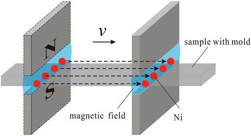
Epoxy resin with good fluidity before curing was used as matrix materials. Ni has good high temperature stability, low coefficient of thermal expansion and excellent magnetic properties, so Ni particles with an average diameter of 1.2 μm were selected as magnetic components. Diethylene triamine was used as curing agent. Ni and epoxy resin with different proportions were stirred uniformly and then poured into a 30 × 10 × 2 mm3 cuboid mold. A vertical magnetic field with narrow spatial distribution was applied on one end of the mold, then moved horizontally to the other end, and finally moved away. In this procedure, Ni was magnetized and pulled from left to right by the magnetic field. If necessary, the magnetic field was moved back to the original end of the mold along different path, during which the mold was not affected by the field. This is one cycle. Multiple cycles were carried out respectively in our experiments, if necessary. The schematic illustration of the preparation of the magnetic-field-driving method is shown in Figure 1. The magnetic field was provided by a combined magnet with an air gap of 3 × 50 × 10 mm3 and 200 ± 1 mT field in center.

FIGURE 1. Schematic representation of experimental set up used for FGMs sample preparation with magnetic-field-driving method.
The microstructures of the cured sample were observed by the optical microscopy (MeF-3, Reichert, Austria). The elemental distribution was analyzed using image analysis techniques. The samples were then cut into small pieces to measure magnetic property by a Vibrating Sample Magnetometer (Lakeshore 7407, USA), electrical resistivity by a High Resistance Meter (ZC90, China), light transmittance by a Spectrophotometer (U-4100, Japan).
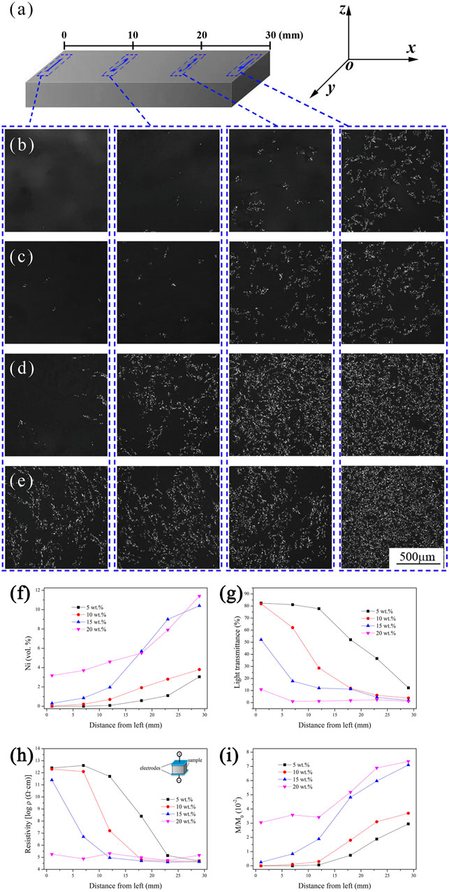
The cross section of the cured sample was defined by oxy plane parallel to the field moving direction as shown in Figure 2A. Figures 2B–E show the optical micrographs of sample with the Ni content of 5, 10, 15, and 20 wt%, respectively. The magnetic field cycled 5 times with a velocity of 1 mm/s. The gray background is identified to be epoxy resin, and bright dots are Ni. Ni increases gradually from left to right in all samples. It suggests that Ni particles move from left to right following the motion of the magnetic field, and finally composition gradients are formed. Especially for the sample with 5 wt% Ni, all particles are driven away from left end by the applied field, while there is still some Ni left in the left end for the sample with 20 wt%.

FIGURE 2. Dimensional orientation of experiment: ox is the field moving direction, oy is the transverse direction and oz is the magnetic field direction, and the corresponding regions of each microstructure figure in Ni/epoxy resin samples (A); Optical micrographs of Ni/epoxy resin samples with various Ni contents: (B) 5 wt%; (C) 10 wt%; (D) 15 wt%; (E) 20 wt%. The applied field of 200 mT cycled 5 times at a velocity of 1 mm/s; Variation of Ni concentration (F), light transmittance (G), electrical resistivity (H) and specific saturation magnetization (I) with different Ni contents as a function of the distance from the left side of the samples.
Figure 2F plots Ni distributions at the cross-section of the samples with various Ni content. Composition gradients with Ni increasing from left to right are observed in all samples. Figure 2G shows the distribution of optical property with the distance from left. The light transmittance decreases gradually along the field moving direction, and also decreases with Ni content of from 5 wt% to 20 wt%. Compared to Figure 2F, the light transmittance of polymer composites is inversely proportional to its concentration of fillers from left to right, because the existence of Ni particles in the composites blocked the light propagation in translucent epoxy resin.
Figure 2H plots the electrical resistivity of the samples in field direction. The inset Figure 2H shows the illustration of the resistivity measurement. It clearly shows that the electrical resistivity in the field direction decrease gradually with the distance from left. The electrical resistivity is critically influenced by the concentration of Ni powders, and the high concentration results in small resistivity.
Figure 2I reveals the variation of specific saturation magnetization in the samples with various Ni content. The samples consist of magnetic Ni and nonmagnetic epoxy resin, so the specific saturation magnetization can exactly represent the volume content of Ni. The specific saturation magnetization increases gradually with the distance from left in all samples, and the high Ni content results in small gradient. However, there are some differences in the numerical value of Ni content between Figures 2F,I. In fact, the value in Figure 2A is calculated from the optical micrographs on cross section by using image analysis techniques, and the distribution of Ni on a specific section also has some contingency. So, the calculated value cannot reflect the actual distribution of Ni very accurately.
The results reveal that the increase of Ni content makes it difficult to achieve composition gradient. With the increase of Ni content, the distance among particles gets small, and the magnetic interaction becomes strong. Chain-like Ni clusters formed along field direction (Yan et al., 2009) under the effects of both the magnetic field and interaction among particles (Peng et al., 2007), which cannot be observed in xoy plane, but in xoz plane (Li et al., 2018). The clusters make Ni move difficultly under magnetic field, which finally results in small composition gradient. Therefore, 10 wt% Ni content was selected for the following study.
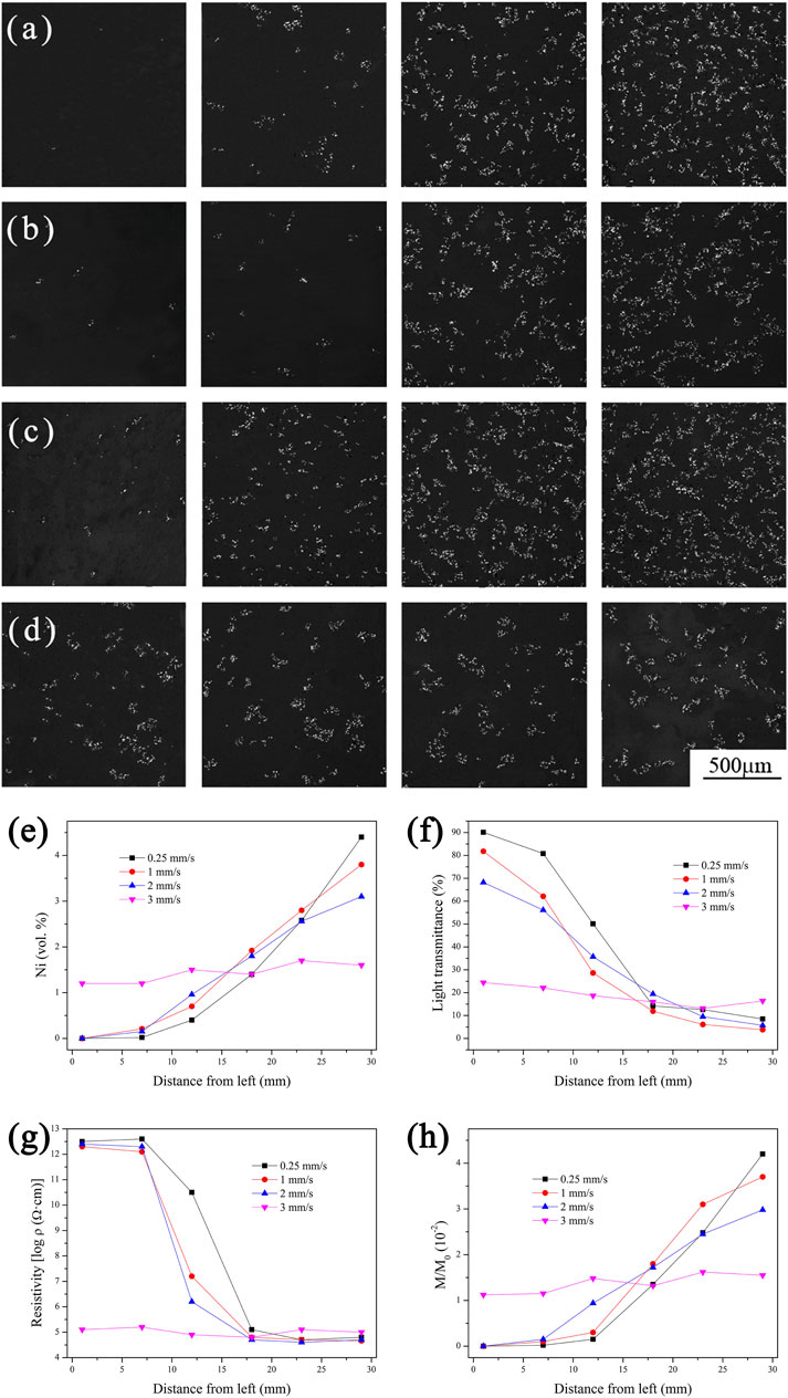
Figures 3A–D show the optical micrographs of the cured samples with the field moving velocity of 0.25, 1, 2, and 3 mm/s, respectively. The magnetic field cycled 5 times on sample. It is obvious that Ni increases gradually from left to right in the samples with the velocity of 0.25 mm/s (Figure 3A), 1 mm/s (Figure 3B) and 2 mm/s (Figure 3C), and the gradient decreases with the increase of velocity. As the velocity reaches 3 mm/s (Figure 3D), Ni seems to distribute almost uniformly everywhere.

FIGURE 3. Optical micrographs of Ni/epoxy resin samples with various field moving velocities: (A) 0.25 mm/s; (B) 1 mm/s; (C) 2 mm/s; (D) 3 mm/s. The applied field of 200 mT cycled 15 times with 10 wt% Ni. Variation of Ni concentration (E), light transmittance (F), electrical resistivity (G) and specific saturation magnetization (H) with different field moving velocities as a function of the distance from the left side of the samples.
Figure 3E plots Ni distributions at the cross-section of the samples with various moving velocities. Ni distributes gradually with the distance from left. The gradient of Ni decreases with the increase of velocity, and almost disappears at the velocity of 3 mm/s. It suggests that the slow moving velocity of magnetic field results in large composition gradient. Figure 3F shows the distribution of optical property along the field moving direction. The light transmittance decreases gradually with the distance from left, and the gradient decreases with the increase of field velocity. Figure 3G plots the electrical resistivity of the samples in field direction. The result shows that the electrical resistivity decrease gradually with the distance from left, and also the gradient decreases with the increase of field velocity. Figure 3H reveals the variation of specific saturation magnetization in the samples with various velocities. The specific saturation magnetization increases gradually with the distance from left in all samples, and the high velocity results in low gradient.
Once Ni particle moves at a velocity through the slurry, which can be regarded as a viscous liquid, it would experience viscous force. The value of viscous force is determined by Stokes’ law (Mánik and Holmedal, 2013), which is proportional to velocity of the Ni particle. The viscous force hinder the free moving of Ni particle, which makes Ni cannot always follow the movement of magnetic field, especially at a relative high velocity. On the contrary, at the low velocity, Ni particle can follow the moving of the field in a high probability, which leads to a steep composition gradient.
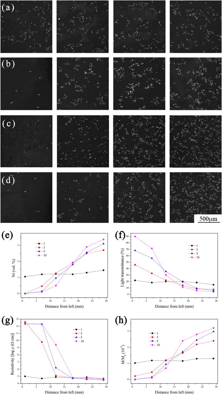
Figures 4A–D show the optical micrographs of the cured samples with the cycle time of 1, 3, 5, and 10, respectively. The velocity of the applied filed was 2 mm/s. For one single cycle (Figure 4A), Ni seems to distribute uniformly on the cross-section from left to right. As cycle time increased to 3 (Figure 4B), Ni starts gradually increasing from left to right. The gradient increases with cycle time (Figures 4B–D), and it becomes quite obvious for 10 cycles.

FIGURE 4. Optical micrographs of Ni/epoxy resin samples with various cycle times: (A) 1; (B) 3; (C) 5; (D) 10. The applied field of 200 mT was applied on the sample with 10 wt% Ni at a velocity of 2 mm/s. Variation of Ni concentration (E), light transmittance (F), electrical resistivity (G) and specific saturation magnetization (H) with different cycle times as a function of the distance from the left side of the samples.
Figure 4E plots Ni distributions at the cross-section of the samples with various cycle times. Ni distributes gradually with the distance from left under the magnetic field. The gradient of Ni increases with cycle time, and reach the maximum with 10 cycles. Figure 4F shows the distribution of optical property along the field moving direction. The light transmittance decreases gradually with the distance from left, while the gradient increases with cycle time. Figure 4G plots the electrical resistivity of the samples in field direction. The result shows that the electrical resistivity decrease gradually with the distance from left, and also the gradient increases with cycle time. Figure 4H reveals the variation of specific saturation magnetization in the samples. The specific saturation magnetization increases gradually with the distance from left in all samples, and the more cycle times result in larger gradient.
As discussed in 3.2, the moving of Ni particle is hindered by the viscous force, and Ni always moves behind the magnetic field. It is impossible to make Ni moves fluently following the magnetic field at only one cycle. The more cycles make more Ni particles move following the field to the right side, and thus form a larger gradient.
In the magnetic field, Ni particle can be considered as magnetic dipole with both +m and−m magnetic poles. Then magnetic forces F1 and F2 act on two magnetic poles, respectively. Suppose the magnetic dipoles are located in the center of the uniform field. Then the two magnetic forces F1 and F2 are equal in magnitude but opposite in direction, so the resultant force is zero. When the magnetic field moves, the force acting on the magnetic poles has changed. Then the component of magnetic force pointing to the moving direction of the field emerges, which makes Ni particle moves following magnetic field.
In this method, all magnetic particles can be driven by the uniform magnetic field, which makes it easy to prepare FGMs. The ideal FGMs with desired composition gradient can be obtained by adjusting constituent parameters, moving velocity, and also cycle times. Generally, the above results indicate that the magnetic-field-driving method has been proved to be an attractive way to develop different kinds of FGMs suitable for scientific and technological applications.
Ni/epoxy resin FGMs were prepared using a magnetic-field-driving method by moving a narrow magnetic field from one end of the sample to the other end with the moving direction perpendicular to the field direction. Ni follows the moving of the magnetic field, and the gradient distribution is obtained. The composition gradients are affected by Ni content, moving velocity, and also cycle times. Compared to the preparation of FGMs by using gradient magnetic field, this magnetic-field-driving method is more effective, attractive and easier to prepare FGMs, which is very promising into scientific and technological applications.
The original contributions presented in the study are included in the article/supplementary material, further inquiries can be directed to the corresponding authors.
All authors listed have made a substantial, direct, and intellectual contribution to the work and approved it for publication.
This work was supported by Zhejiang Province Public Welfare Technology Application Research Project (LGG19E010002), Natural Science Foundation of Zhejiang Province (LY16E030004), National Natural Science Foundation of China (No. 51002132, 51402276, U1809216).
The authors declare that the research was conducted in the absence of any commercial or financial relationships that could be construed as a potential conflict of interest.
All claims expressed in this article are solely those of the authors and do not necessarily represent those of their affiliated organizations, or those of the publisher, the editors and the reviewers. Any product that may be evaluated in this article, or claim that may be made by its manufacturer, is not guaranteed or endorsed by the publisher.
Anh, V. T. T., Hong Cong, P., Huy Bich, D., and Dinh Duc, N. (2016). On the Linear Stability of Eccentrically Stiffened Functionally Graded Annular Spherical Shell on Elastic Foundations. Adv. Compos. Mater. 25, 525–540. doi:10.1080/09243046.2016.1187819
Carvalho, O., Buciumeanu, M., Miranda, G., Madeira, S., and Silva, F. S. (2016). Development of a Method to Produce FGMs by Controlling the Reinforcement Distribution. Mater. Des. 92, 233–239. doi:10.1016/j.matdes.2015.12.032
Dong, M., Liu, T., Liao, J., Xiao, Y.-b., Yuan, Y., and Wang, Q. (2016). In Situ preparation of Symmetrically Graded Microstructures by Solidification in High-Gradient Magnetic Field after Melt and Partial-Melt Processes. J. Alloys Comp. 689, 1020–1027. doi:10.1016/j.jallcom.2016.08.074
Gotman, I., and Gutmanas, E. Y. (2018). Reactive Forging - Pressure Assisted Thermal Explosion Mode of SHS for Processing Dense In Situ Composites and Structural Parts: A Review. Adv. Eng. Mater. 20. 1800376. doi:10.1002/adem.201800376
Hangai, Y., Takahashi, K., Utsunomiya, T., Kitahara, S., Kuwazuru, O., and Yoshikawa, N. (2012). Fabrication of functionally graded aluminum foam using aluminum alloy die castings by friction stir processing. Mater. Sci. Eng. A 534, 716–719. doi:10.1016/j.msea.2011.11.100
Hu, S., Gagnoud, A., Fautrelle, Y., Moreau, R., and Li, X. (2018). Fabrication of Aluminum alloy Functionally Graded Material Using Directional Solidification under an Axial Static Magnetic Field. Sci. Rep. 8, 7945. doi:10.1038/s41598-018-26297-5
Hu, T.-j., Li, X.-d., Li, Y.-h., Wang, H., and Wang, J. (2011). Axial Graded Silicon Carbide Fibers with Fluctuating Carbon Layer and Sinusoidal Electrical Resistivity. Mater. Lett. 65, 2562–2564. doi:10.1016/j.matlet.2011.05.058
Kang, N., Coddet, P., Wang, J., Yuan, H., Ren, Z., Liao, H., et al. (2017). A Novel Approach to Iin-Ssitu Produce Functionally Graded Silicon Matrix Composite Materials by Selective Laser Melting. Compos. Structures 172, 251–258. doi:10.1016/j.compstruct.2017.03.096
Li, J., Peng, X., Yang, Y., Xu, J., Wang, P., Hong, B., et al. (2018). A Novel Magnetic-Field-Driving Method for Fabricating Ni/epoxy Resin Functionally Graded Materials. Mater. Lett. 222, 70–73. doi:10.1016/j.matlet.2018.03.180
Liu, T., Wang, Q., Gao, A., Zhang, C., Wang, C., and He, J. (2007). Fabrication of Functionally Graded Materials by a Semi-solid Forming Process under Magnetic Field Gradients. Scripta Materialia 57, 992–995. doi:10.1016/j.scriptamat.2007.08.011
Loja, M. A. R., Mota Soares, C. M., and Barbosa, J. I. (2014). Optimization of Magneto-Electro-Elastic Composite Structures Using Differential Evolution. Compos. Structures 107, 276–287. doi:10.1016/j.compstruct.2013.08.005
Mahamood, R. M., and Akinlabi, E. T. (2015). Laser Metal Deposition of Functionally Graded Ti6Al4V/TiC. Mater. Des. 84, 402–410. doi:10.1016/j.matdes.2015.06.135
Mánik, T., and Holmedal, B. (2013). On the Criterion for Compensation to Avoid Elastic-Plastic Transients during Strain Rate Change Tests. Acta Materialia 61, 653–659. doi:10.1016/j.actamat.2012.10.013
Mao, Y. Q., Ai, S. G., Fang, D. N., Fu, Y. M., and Chen, C. P. (2013). Elasto-plastic Analysis of Micro FGM Beam Basing on Mechanism-Based Strain Gradient Plasticity Theory. Compos. Structures 101, 168–179. doi:10.1016/j.compstruct.2013.01.027
Marteau, J., and Bouvier, S. (2016). Characterization of the Microstructure Evolution and Subsurface Hardness of Graded Stainless Steel Produced by Different Mechanical or Thermochemical Surface Treatments. Surf. Coat. Tech. 296, 136–148. doi:10.1016/j.surfcoat.2016.04.010
Nardi, T., Leterrier, Y., Karimi, A., and Månson, J.-A. E. (2014). A Novel Synthetic Strategy for Bioinspired Functionally Graded Nanocomposites Employing Magnetic Field Gradients. RSC Adv. 4, 7246–7255. doi:10.1039/c3ra46731g
Peng, X., Yan, M., and Shi, W. (2007). A New Approach for the Preparation of Functionally Graded Materials via Slip Casting in a Gradient Magnetic Field. Scripta Materialia 56, 907–909. doi:10.1016/j.scriptamat.2006.12.020
Siddhartha, A. P., Patnaik, A., and Bhatt, A. D. (2011). Mechanical and Dry Sliding Wear Characterization of Epoxy-TiO2 Particulate Filled Functionally Graded Composites Materials Using Taguchi Design of experiment. Mater. Des. 32, 615–627. doi:10.1016/j.matdes.2010.08.011
Song, C., Li, Q., Li, H., and Zhai, Q. (2008). Effect of Pulse Magnetic Field on Microstructure of Austenitic Stainless Steel during Directional Solidification. Mater. Sci. Eng. A 485, 403–408. doi:10.1016/j.msea.2007.07.079
Wang, J., Pan, Z., Ma, Y., Lu, Y., Shen, C., Cuiuri, D., et al. (2018). Characterization of Wire Arc Additively Manufactured Titanium Aluminide Functionally Graded Material: Microstructure, Mechanical Properties and Oxidation Behaviour. Mater. Sci. Eng. A 734, 110–119. doi:10.1016/j.msea.2018.07.097
Yan, M., Peng, X., and Ma, T. (2009). Microstructures of Ni-ZrO2 Functionally Graded Materials Fabricated via Slip Casting under Gradient Magnetic fields. J. Alloys Comp. 479, 750–754. doi:10.1016/j.jallcom.2009.01.042
Keywords: functionally graded materials (FGM), magnetic-field-driving method, composition gradient, microstructure, magnetic property
Citation: Zhan T, Chang J and Li J (2021) Fabrication, Microstructure and Properties of Nickel/Epoxy Resin Functionally Graded Materials With Magnetic-Field-Driving Method. Front. Mater. 8:639021. doi: 10.3389/fmats.2021.639021
Received: 08 December 2020; Accepted: 08 June 2021;
Published: 01 September 2021.
Edited by:
Liang Liu, National University of Singapore, SingaporeCopyright © 2021 Zhan, Chang and Li. This is an open-access article distributed under the terms of the Creative Commons Attribution License (CC BY). The use, distribution or reproduction in other forums is permitted, provided the original author(s) and the copyright owner(s) are credited and that the original publication in this journal is cited, in accordance with accepted academic practice. No use, distribution or reproduction is permitted which does not comply with these terms.
*Correspondence: Jing Li, amluZ2xpQGNqbHUuZWR1LmNu
Disclaimer: All claims expressed in this article are solely those of the authors and do not necessarily represent those of their affiliated organizations, or those of the publisher, the editors and the reviewers. Any product that may be evaluated in this article or claim that may be made by its manufacturer is not guaranteed or endorsed by the publisher.
Research integrity at Frontiers

Learn more about the work of our research integrity team to safeguard the quality of each article we publish.