 Patrick Dorin
 K. W. Wang
94% of researchers rate our articles as excellent or good
Learn more about the work of our research integrity team to safeguard the quality of each article we publish.
Find out more
ORIGINAL RESEARCH article
Front. Mater., 12 January 2021
Sec. Mechanics of Materials
Volume 7 - 2020 | https://doi.org/10.3389/fmats.2020.602996
This article is part of the Research TopicCutting-Edge Metastructures: Micro-Architected and Active MetamaterialsView all 8 articles
Many engineering applications leverage metamaterials to achieve elastic wave control. To enhance the performance and expand the functionalities of elastic waveguides, the concepts of electronic transport in topological insulators have been applied to elastic metamaterials. Initial studies showed that topologically protected elastic wave transmission in mechanical metamaterials could be realized that is immune to backscattering and undesired localization in the presence of defects or disorder. Recent studies have developed tunable topological elastic metamaterials to maximize performance in the presence of varying external conditions, adapt to changing operating requirements, and enable new functionalities such as a programmable wave path. However, a challenge remains to achieve a tunable topological metamaterial that is comprehensively adaptable in both the frequency and spatial domains and is effective over a broad frequency bandwidth that includes a subwavelength regime. To advance the state of the art, this research presents a piezoelectric metamaterial with the capability to concurrently tailor the frequency, path, and mode shape of topological waves using resonant circuitry. In the research presented in this manuscript, the plane wave expansion method is used to detect a frequency tunable subwavelength Dirac point in the band structure of the periodic unit cell and discover an operating region over which topological wave propagation can exist. Dispersion analyses for a finite strip illuminate how circuit parameters can be utilized to adjust mode shapes corresponding to topological edge states. A further evaluation provides insight into how increased electromechanical coupling and lattice reconfiguration can be exploited to enhance the frequency range for topological wave propagation, increase achievable mode localization, and attain additional edge states. Topological guided wave propagation that is subwavelength in nature and adaptive in path, localization, and frequency is illustrated in numerical simulations of thin plate structures. Outcomes from the presented work indicate that the easily integrable and comprehensively tunable proposed metamaterial could be employed in applications requiring a multitude of functions over a broad frequency bandwidth.
In recent years, it has been recognized that wave control utilizing elastic metamaterials can enhance performance and expand functionalities in many applications, such as energy harvesting, noise isolation, sensing, communications, filtering, and cloaking (Hussein et al., 2014; Fang et al., 2018; Wang et al., 2020). One objective of elastic metamaterials that has received significant attention is the confinement of elastic waves to a specified path or location through the formation of a waveguide. Conventional elastic waveguides obtain wave confinement by creating an inclusion where the wave can localize within a periodic lattice (Kafesaki et al., 2000; Khelif et al., 2004; Benchabane et al., 2005; Oudich et al., 2010; Casadei et al., 2012; Liu et al., 2020). These conventional waveguides can suffer from performance degradation when disorder (e.g., a sharp turn in the waveguide) or defects (e.g., a manufacturing imperfection) exist within the periodic lattice (Sun and Wu, 2006; Pal and Ruzzene, 2017). To avoid this performance degradation and expand the functionalities of elastic waveguides, the concepts that underly topologically protected conducting states in electronic materials (Hasan and Kane, 2010) have been employed in elastic metamaterials (Huber, 2016; Ma et al., 2019). Topological metamaterials are immune to various classes of disorder and defects that are oftentimes found in practical engineering applications, thus enabling lossless transmission along any desired wave path. To achieve topologically protected wave propagation that is localized to waveguides in two-dimensional systems, the elastic analogs of the quantum Hall effect (QHE), quantum spin Hall effect (QSHE), and quantum valley Hall effect (QVHE) have been extensively investigated.
Protected wave propagation that is confined to a waveguide is obtained through the activation of localized topological edge states that arise from the QHE, QSHE, and QVHE. Due to the active/moving components that are generally required to break time-reversal symmetry (TRS) for the QHE (von Klitzing, 1986; Nash et al., 2015; Wang P. et al., 2015; Wang Y. T. et al., 2015) and the complex geometries necessary to achieve a double Dirac cone (a degeneracy where four cones meet) in the dispersion relation for the QSHE (Kane and Mele, 2005; Mousavi et al., 2015; Süsstrunk and Huber, 2015; Wu and Hu, 2015; Chaunsali et al., 2018; Miniaci et al., 2018), the relatively simpler QVHE has garnered significant attention. The QVHE requires the formation of a single Dirac cone (a degeneracy where two cones meet) in the dispersion relation of the unit cell. This single Dirac cone is opened with a lattice perturbation that breaks space inversion symmetry (SIS), which produces a bandgap that can support topological edge states due to valley-dependent topological properties (Nakada et al., 1996; Rycerz et al., 2007; Xiao et al., 2007; Peres, 2010). Topologically protected wave transmission according to the elastic analog of the QVHE has been obtained in reticular structures (Vila et al., 2017; Liu and Semperlotti, 2019; Miniaci et al., 2019) and continuous thin plates with periodically placed masses (Chen et al., 2017; Yu et al., 2018; Zhu et al., 2018) or inclusions (Du et al., 2020). These structures emulate the elastic QVHE by exploiting a periodic impedance mismatch (Bragg scattering mechanism), and thus the resulting topological edge states exist at frequencies corresponding to wavelengths that are dependent on the lattice constant. The addition of local mass resonators (Torrent et al., 2013; Pal and Ruzzene, 2017; Lera et al., 2019; Wang et al., 2019; Zhang et al., 2020) and acoustic black holes (Ganti et al., 2020) to continuous plates has facilitated the achievement of topological edge states at frequencies that are determined by the characteristics of the local element (mass resonator or acoustic black hole). Topological wave propagation at low frequencies corresponding to wavelengths that are larger than the lattice constant has been demonstrated by carefully selecting the properties of these local elements (Pal and Ruzzene, 2017; Chaunsali et al., 2018; Wang et al., 2019; Zhang et al., 2020). Subwavelength topological metamaterials such as these could be highly valuable for engineering applications that require wave control at low frequencies in a size-constrained environment.
To extend beyond the functionalities available in fixed structures and enable adaptivity to varying operating requirements and external conditions, many recent investigations have focused on introducing tunability to topological metamaterials. The spatial path of topological wave propagation has been demonstrated to be adjustable by applying an external magnetic field (Zhang et al., 2019), modifying mechanical boundary conditions (Darabi and Leamy, 2019; Tang et al., 2019), adding an elastic foundation (Al Ba’ba’a et al., 2020), connecting negative capacitance piezoelectric circuitry (Riva et al., 2018; Darabi et al., 2020), or switching stable states in bistable elements (Wu et al., 2018). The shape and localization of topological edge states have been tuned by exploiting an applied strain field (Liu and Semperlotti, 2018). Initial studies involving real-time frequency tuning of topological edge states have shown that an applied temperature (Liu et al., 2019), strain field (Nguyen et al., 2019), or electrical field (Zhou et al., 2020) can increase the frequency range over a limited region that is related to the Bragg mechanism or the magnitude of lattice perturbation.
The tunable topological metamaterials that have been investigated thus far have each concentrated on tailoring an individual characteristic of the topological wave to unlock novel functions and enhance performance in devices exhibiting elastic wave control. However, to fully realize the potential of topological metamaterials in wave control platforms and enable robust performance over a broad set of functionalities, an elastic metamaterial with multiple tunable topological characteristics must be developed. To date, concurrent tunability of the frequency and spatial characteristics of topological edge states has yet to be fully explored in a singular elastic metamaterial. Such a metamaterial would be of great benefit for devices such as wave filters, multiplexers, and energy harvesters that must route energy over a large frequency bandwidth. Besides primarily focusing on one adaptive characteristic, the currently established tunable topological metamaterials generally rely on the Bragg mechanism to generate a Dirac cone. Due to the interaction of platform-specific tuning parameters with the underlying physics of the Bragg mechanism, these metamaterials are either incapable of on-line frequency tuning (e.g., they are path tunable only) or can only practically do so over a limited range. Moreover, structures fabricated from these metamaterials would need to be large to control energy at low frequencies that correspond with fundamental system modes, which can be critical in structural applications. As a result, an easily integrable topological metamaterial that is capable of subwavelength elastic wave control and programmable over a broad frequency bandwidth has yet to be developed.
To advance the state of the art, the presented research proposes a piezoelectric topological metamaterial harnessing integrated resonant circuitry for comprehensively tunable subwavelength wave control. The goal of this investigation is to uncover insights into critical adaptive parameters and synthesize a framework for the attainment of programmable topological wave propagation using resonant electromechanical metamaterials. In contrast to previous works, the proposed methodology and approach has achieved clear advancements: (a) the rich tailorable characteristics of the piezoelectric metamaterial enable the concurrent adaptation of the frequency range, path, and mode shape of topological edge states and (b) this on-demand tunability of topological properties is achieved for the first time in a subwavelength (i.e., compact) and load-bearing thin plate structure.
To accomplish the research objective, this manuscript presents the evaluation of the dispersion relation for the unit cell from the plane wave expansion (PWE) method. The PWE method is selected because of its concise nature and computational efficiency when compared to the often-used finite element (FE) method, since there can be a low (e.g., 50–100) number of degrees of freedom required to achieve an accurate result from PWE calculations for thin plate structures (Xiao et al., 2012; Pal and Ruzzene, 2017). This method is utilized to establish the working principle for the achievement of topological edge states from the QVHE. Beyond establishing a working principle for the attainment of topological edge states for fixed system parameters, the advantages of the PWE method facilitate a comprehensive parameter study through rapid calculations of the metamaterial dispersion relation. A parametric analysis is performed to identify and explore an achievable operating region for tunable topological wave propagation. Numerical computations of the dispersion relation for a finite strip of connected unit cells uncover how circuit parameters can enable the adjustment of topological edge states. Further analysis is conducted to investigate how topological edge state adaptivity can be augmented by the connection of negative capacitance to enhance electromechanical coupling and lattice reconfiguration via shorting circuits to obtain an additional Dirac cone. Finally, the activation of topological edge states for the achievement of guided topological wave propagation at lattice interfaces and boundaries is revealed by numerical simulations of a thin plate structure.
As shown in Figure 1, the proposed piezoelectric metamaterial is comprised of a bimorph thin plate with substrate (gray) and piezoelectric (yellow) layers. The substrate layer has thickness
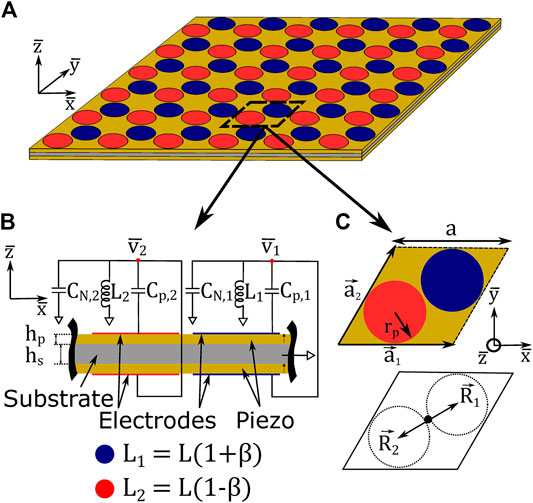
FIGURE 1. (A) Isometric view of piezoelectric metamaterial, with unit cell enclosed in dashed lines. (B) Cross-section and (C) top view of metamaterial unit cell. Blue indicates electrode geometry connected to circuit 1, red indicates electrode geometry connected to circuit 2.
In the derivation of the theoretical model for the metamaterial, small deflections and a thin structure (in the
where
where
where
To generalize the results, a nondimensionalization scheme is adopted and the resulting equations are:
where the non-dimensional flexural displacement, voltage, time, and length scales are defined as:
To attain the dispersion diagram (i.e., band structure) of the metamaterial, the dispersion relation of the unit cell is analyzed using the PWE method. For this study, the number of electrode pairs (capacitors) in the unit cell is set to
where
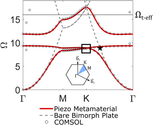
FIGURE 2.
Eq. 10 is obtained. Similarly, by substituting Eq. 8 into Eq. 7, Eq. 11 is obtained. The following equations define the dispersion relation of the metamaterial unit cell:
where
To evaluate the dispersion relation for the system, Eqs 10, 11 are arranged in the form of the classical eigenvalue problem:
where the eigenvalues
Per Eq. 12,
This term, which is present in Eq. 10, measures the level of effective electromechanical coupling when accounting for the connected negative capacitor. Thus, by careful selection of the negative capacitance ratio (e.g.,
Since
There is a physical explanation for the derived stability criterion. The parallel-connected negative capacitor reduces the effect of the inherent capacitance of an electrode pair, causing a reduction in the total capacitance present in the corresponding circuit (
In addition to changing the effective electromechanical coupling, the inclusion of negative capacitance influences the effective nondimensional tuning frequency of the resonant circuits. Through observation of Eq. 11, this influence can be measured as:
where
In this section, the working principle is outlined for the attainment of subwavelength topological wave propagation using the proposed metamaterial. A unit cell dispersion analysis is conducted to identify lattices with nontrivial topological characteristics and define metrics that are indicators of waveguide performance. A finite strip analysis is undertaken to investigate how localized topological edge states can be obtained through the connection of topologically distinct lattices. Numerical simulations are performed to illustrate how these edge states can be exploited to achieve guided topological wave propagation that is tunable in both the frequency and spatial domains.
The band structure of the proposed metamaterial is obtained through a unit cell dispersion analysis. For this study, PZT-5H (a commonly utilized piezoceramic) is selected as the material for the piezoelectric layers and aluminum is selected as the material for the substrate layer. The material properties associated with PZT-5H and aluminum that are used in dispersion calculations are listed in Table 1. The geometric dimensions specified for the analysis are also included in Table 1. The layer thicknesses
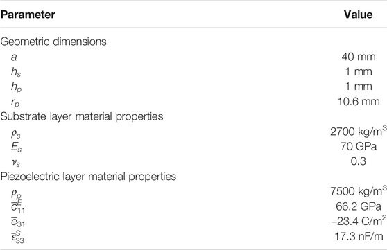
TABLE 1. Definition of geometric and material properties.
Due to the presence of
To obtain topological edge states per the QVHE, different inductance values are selected for each of the two circuits in the unit cell (
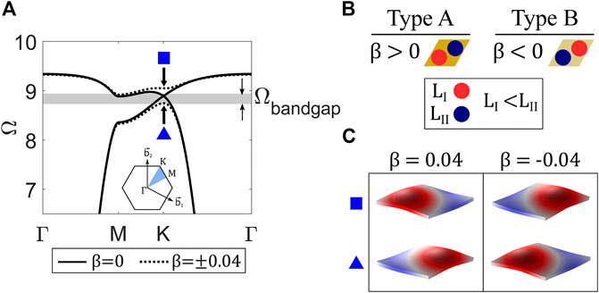
FIGURE 3. (A) Dispersion curves (specifically, the first and second bands) for
Where
where
The topological interface state must be excited in a way that does not activate the bulk modes of a given structure to obtain localized topological wave propagation. To achieve this goal, the interface state is excited at a frequency within the common topological bandgap that is found in the dispersion diagrams of the Type A and Type B lattices (
Based on this discussion, the performance criteria defined for this investigation that are obtainable from the unit cell dispersion analysis are 1)
A dispersion analysis is conducted for a finite strip of unit cells containing an interface between Type A and Type B lattices to demonstrate the emergence of topologically protected interface states. For this finite strip analysis, all parameters are defined identically to the unit cell analysis discussed in the previous section (
where
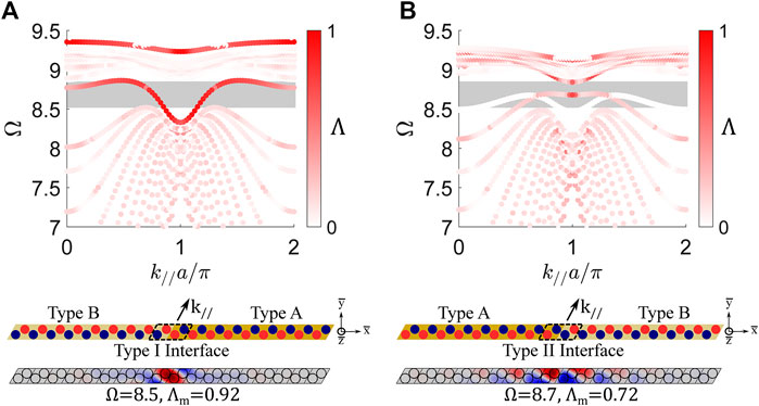
FIGURE 4. (A) Band structure for a finite strip (|
An additional localized state exists near
Two observations are gained from the finite strip analysis. First, the proposed metamaterial enables the obtainment of symmetric and antisymmetric topological interface states, which aligns with previous investigations into the QVHE (Zhu et al., 2018). Due to the tunability of the circuit parameters in the proposed metamaterial, switching between these interface state types (symmetric and antisymmetric) could easily be achieved in practice. Second, the finite strip dispersion analysis supports the performance requirement for a nontrivial topological bandgap (
The ability to achieve topological wave propagation from the interface states is investigated with FE simulations of a plate constructed from the proposed metamaterial. The proposed metamaterial enables concurrent tunability of the topological wave path, mode shape, and frequency, which advances upon previously developed platforms that are generally narrowband in nature and only focus on one tailorable characteristic. Each of the proposed metamaterial’s tailorable properties are investigated separately in this manuscript to simplify the analysis. The path tunability of the topologically protected waveguide is examined in this section, while comprehensive analyses on frequency and mode shape tailoring are contained in section Parametric Study– Frequency and Mode Shape Tunability.
The plate used for FE simulations consists of a 16 by 20 lattice of unit cells, with low reflection conditions applied along all outer boundaries to suppress reflections (see left column of Figure 5 for plate schematics). The lattice contains an interface between Type A and Type B unit cells, which is enclosed by the black lines in Figures 5A–D. A resistance (
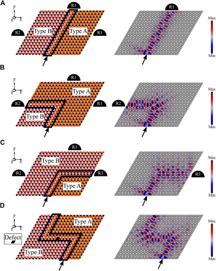
FIGURE 5. Schematics (left column) and steady-state response (right column) for guided wave propagation along (A) straight, (B) sharp corner, (C) shallow corner, and (D) “Z-shape with defect” interfaces. In the schematics, R1, R2, and R3 represent output signal receivers and black lines enclose the interface between Type A and Type B lattices. Circuit parameters are defined as:
In this section, a parametric study is undertaken to extensively explore the adaptive characteristics of the proposed metamaterial and develop a detailed understanding of system parameters that govern performance. A framework is developed to assess the frequency and interface mode shape tunability of the metamaterial and uncover insights into the impact of electromechanical coupling on topological elastic wave control.
Since topological wave propagation occurs at a frequency near the Dirac frequency (
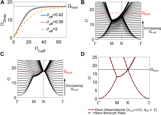
FIGURE 6. (A) Dirac frequency
According to Figure 6A, the achievable frequency range for
A lattice perturbation must be applied to open a topological bandgap from the Dirac point and achieve topological edge states per the QVHE. While the previously presented analysis (see section Working Principle– Obtainment of Tunable Topological Wave Propagation) demonstrates this working principle under a fixed set of parameters, further exploration is required to fully evaluate the tunability of the proposed metamaterial. Thus, a parametric study involving the inductance perturbation parameter
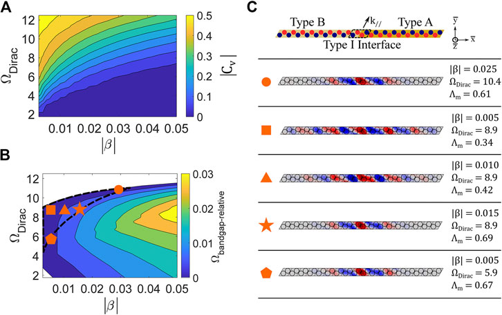
FIGURE 7. (A) Valley Chern magnitude |
Aside from enabling an adjustable frequency range for topological interface states, the proposed metamaterial also facilitates the tailoring of interface mode shape and localization. The ability to adjust interface mode localization is investigated by varying the inductance perturbation parameter
The effect of electromechanical coupling on the vibration attenuation performance of piezoelectric metamaterials is well documented (Hagood and von Flotow, 1991; Tang and Wang, 2001; Sugino et al., 2017). In this investigation, the influence of the effective electromechanical coupling factor
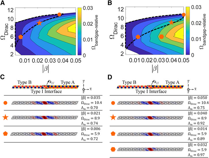
FIGURE 8. (A) Relative bandgap
The expansion of the achievable operating region signifies an increased level of tunability. In terms of frequency range, the achievable operating region is extended to lower frequencies (while maintaining an upper bound of approximately
These findings indicate that electromechanical coupling plays a crucial role in determining the extent of the tunability of the topological interface state. Thus, care must be taken to maximize the effective electromechanical coupling through material selection and geometric design. In addition, negative capacitance circuitry could be utilized to artificially enhance the coupling and achieve topological interface states with a broader frequency range and increased displacement localization.
FE simulations of plates constructed from the proposed metamaterial are conducted to verify that tunable topological wave propagation can be realized by activation of the topological interface states contained within the achievable operating region. Plates with straight line and Z-shaped Type I interfaces are harmonically excited at the locations indicated by the arrows in Figure 9A. Geometric, material, and negative capacitance (
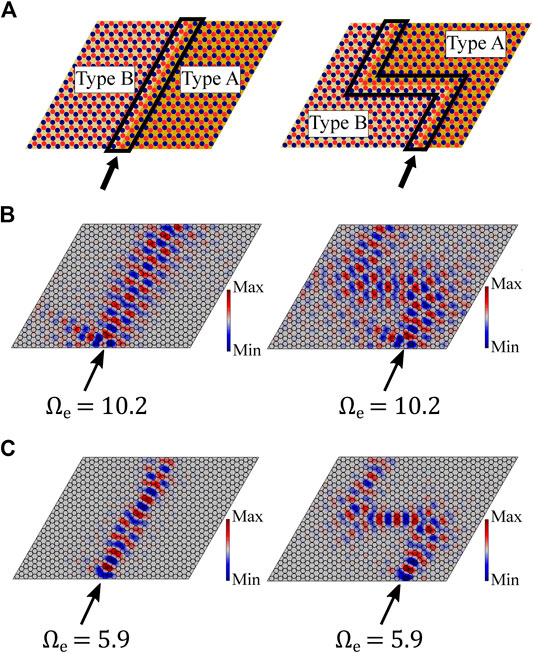
FIGURE 9. (A) Schematics for thin plate metastructures with straight and Z-shaped Type I lattice interfaces (enclosed in black lines). A harmonic out-of-plane point excitation is applied where indicated by the arrow. Negative capacitance circuity is connected such that
Notably, for the low-frequency case (
The architecture of the proposed metamaterial can also be exploited to enhance adaptivity through lattice reconfiguration, which has been used in previous investigations to achieve tailorable bandgaps and waveguides in topologically trivial structures (Thota et al., 2017; Thota and Wang, 2018). In this section, lattice reconfiguration is explored as a mechanism to enhance the frequency range of topological waves and obtain additional topological edge states.
Figure 10A contains schematics for three different lattice configurations that are attainable with the proposed metamaterial. Figure 10B contains the corresponding dispersion diagrams for each lattice configuration with circuit conditions specified such that
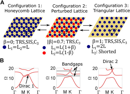
FIGURE 10. (A) Schematics for three lattice configurations attainable through circuit tailoring in the proposed metamaterial. Circuits are connected to electrodes that are represented by blue and red circles. For Configuration 3, electrodes pertaining to shorted circuits are omitted for clarity. Unit cell (enclosed in black dashed lines) circuit parameter details and lattice symmetries are listed below each schematic. (B) Dispersion diagrams corresponding to lattice Configurations 1-3 calculated using the PWE method with
The same process described in previous sections for Dirac 1 is followed to construct interface states from Dirac 2. Figure 10A includes the schematic for a lattice (defined as Configuration 2: Perturbed Lattice) with the inductance perturbation parameter
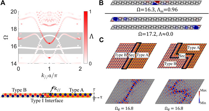
FIGURE 11. (A) Band structure for a finite strip (|
To demonstrate guided wave propagation, plates are constructed with straight and Z-shaped Type I interfaces and excited harmonically (
Results from the finite strip dispersion analysis for a Type I interface (Figure 11) suggest that boundary states are readily achievable from Dirac 2. To further investigate the formation of boundary states from Dirac 2, a dispersion analysis is conducted for a finite strip with 18 Type B unit cells (no interface is present, see schematic in Figure 12A). The left boundary is specified as fixed, the right boundary is specified as free, and periodic boundary conditions are applied in the
where
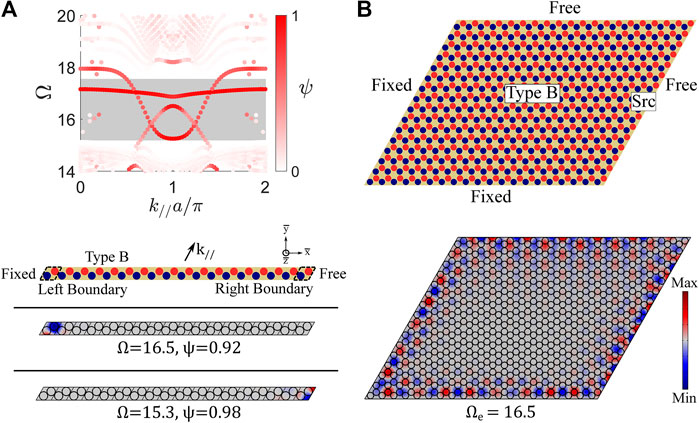
FIGURE 12. (A) Band structure for a finite strip (|
A plate is constructed with boundary conditions (free and fixed) specified such that the outlined boundary states are supported at all four boundaries. The plate is excited harmonically (
This research proposes and develops a topological metamaterial that harnesses resonant piezoelectric circuitry to enable comprehensively tunable elastic wave control. Overall, this investigation advances the state of the art by enabling and exploring the adaptation of topological wave path, frequency, and edge mode shape in a single mechanical platform for the first time. The proposed metamaterial operates over a broad frequency bandwidth and can be integrated in a compact fashion for applications that require control of large-wavelength (i.e., low-frequency) waves due to its subwavelength characteristic, which constitutes a breakthrough in the field of tunable topological elastic waves.
In this manuscript, the tunability of wave path, frequency range, and edge states is explored through a systematic analysis of the dispersion properties and dynamic response characteristics of the proposed metamaterial. A subwavelength and frequency tunable Dirac point (Dirac 1) is uncovered, and it is revealed that symmetric and antisymmetric topological interface states can be obtained from it. FE simulations illuminate how these interface states can be activated to achieve guided elastic wave transmission that is robust to disorder and defects and can be manipulated on-demand into a myriad of desired directions. A deeper understanding of the adaptive characteristics of the metamaterial is formed through parametric studies. A finite tunable frequency range and its underlying physical basis are discovered for Dirac 1. An achievable operating region is defined for topological interface states derived from Dirac 1, where it is learned that interface states that meet specified performance metrics are achievable over a wide frequency bandwidth that comprises a subset of the Dirac 1 frequencies. These findings offer new insights into frequency tunability that may be leveraged in future studies concerning Dirac dispersions and the QVHE in locally resonant elastic metamaterials. Further exploration of the achievable operating region illuminates how circuit parameters can be utilized to tune the displacement field of a waveguide by tailoring the localization and shape of the interface state. The operating region is used as a framework to study the role of electromechanical coupling in topological wave propagation for the first time. Results indicate that increased electromechanical coupling enhances the frequency range and achievable interface mode localization of the interface states. Lattice reconfiguration is also investigated as a method to tailor the topological properties of the proposed metamaterial. Analysis of a triangular lattice obtained through shorting circuits reveals that a second Dirac point (Dirac 2) can be achieved in a high-frequency range that extends beyond the operating region for Dirac 1 interface states. Boundary states and additional interface states are shown to be obtainable from Dirac 2, and numerical simulations illustrate how these states can be exploited to achieve exceptional guided wave phenomena.
The outcomes from this investigation provide fundamental insights into the influence of locally resonant elements, electromechanical coupling, and lattice reconfiguration in adaptive topological metamaterials exhibiting the QVHE, presenting a basis for further exploration. The proposed topological metamaterial may be employed to achieve subwavelength elastic wave control that is robust to practical considerations (eg., sharp corners or lattice imperfections) and adaptive in real-time to shifting operating requirements and external conditions. These beneficial features could be harnessed to improve performance and expand functionalities in a range of applications requiring adaptive and robust elastic wave control, such as vibration isolators, wave filters/multiplexers, and energy harvesters.
The raw data supporting the conclusion of this article will be made available by the authors, without undue reservation.
PD and KW formulated the presented idea. PD developed the mathematical framework, performed analytical and numerical computations, and drafted the manuscript. KW discussed results with PD, provided research direction/advisement, and edited the manuscript.
This material is based upon work supported by the National Science Foundation under Award No. 1661568. PD also acknowledges financial support from the Rackham Merit Fellowship at the University of Michigan.
The authors declare that the research was conducted in the absence of any commercial or financial relationships that could be construed as a potential conflict of interest.
The authors thank Xiang Liu and Megan Hathcock at the University of Michigan Structural Dynamics and Controls Lab for their useful suggestions and participation in discussions regarding topological metamaterials and FE modeling using COMSOL Multiphysics.
The Supplementary Material for this article can be found online at: https://www.frontiersin.org/articles/10.3389/fmats.2020.602996/full#supplementary-material.
Al Ba’ba’a, H., Yu, K., and Wang, Q. (2020). Elastically-supported lattices for tunable mechanical topological insulators. Extrem. Mech. Lett. 38, 100758. doi:10.1016/j.eml.2020.100758
Benchabane, S., Khelif, A., Choujaa, A., Djafari-Rouhani, B., and Laude, V. (2005). Interaction of waveguide and localized modes in a phononic crystal. Europhys. Lett. 71, 570–575. doi:10.1209/epl/i2005-10131-2
Berardengo, M., Thomas, O., Giraud-Audine, C., and Manzoni, S. (2016). Improved resistive shunt by means of negative capacitance: new circuit, performances and multi-mode control. Smart Mater. Struct. 25, 075033. doi:10.1088/0964-1726/25/7/075033
Berry, M. V. (1984). Quantal phase factors accompanying adiabatic changes. Proc. R. Soc. London A. Math. Phys. Sci. 392, 45–57. doi:10.1142/9789813221215_0006
Casadei, F., Delpero, T., Bergamini, A., Ermanni, P., and Ruzzene, M. (2012). Piezoelectric resonator arrays for tunable acoustic waveguides and metamaterials. J. Appl. Phys. 112, 064902. doi:10.1063/1.4752468
Chaunsali, R., Chen, C. W., and Yang, J. (2018). Subwavelength and directional control of flexural waves in zone-folding induced topological plates. Phys. Rev. B 97, 054307. doi:10.1103/PhysRevB.97.054307
Chen, J. J., Huo, S. Y., Geng, Z. G., Huang, H. B., and Zhu, X. F. (2017). Topological valley transport of plate-mode waves in a homogenous thin plate with periodic stubbed surface. AIP Adv. 7, 115215. doi:10.1063/1.5006010
Darabi, A., Collet, M., and Leamy, M. J. (2020). Experimental realization of a reconfigurable electroacoustic topological insulator. Proc. Natl. Acad. Sci.U.S.A. 117, 16138–16142. doi:10.1073/pnas.1920549117
Darabi, A., and Leamy, M. J. (2019). Reconfigurable topological insulator for elastic waves. J. Acoust. Soc. Am. 146, 773–781. doi:10.1121/1.5114920
Du, Z., Chen, H., and Huang, G. (2020). Optimal quantum valley Hall insulators by rationally engineering Berry curvature and band structure. J. Mech. Phys. Solid. 135, 103784. doi:10.1016/j.jmps.2019.103784
Fang, H., Chu, S. C. A., Xia, Y., and Wang, K. W. (2018). Programmable self-locking origami mechanical metamaterials. Adv. Mater. 30, 1706311. doi:10.1002/adma.201706311
Ganti, S. S., Liu, T. W., and Semperlotti, F. (2020). Topological edge states in phononic plates with embedded acoustic black holes. J. Sound Vib. 466, 115060. doi:10.1016/j.jsv.2019.115060
Gao, X., Wu, J., Yu, Y., Chu, Z., Shi, H., and Dong, S. (2018). Giant piezoelectric coefficients in relaxor piezoelectric ceramic PNN-PZT for vibration energy harvesting. Adv. Funct. Mater. 28, 1706895. doi:10.1002/adfm.201706895
Hagood, N. W., and von Flotow, A. (1991). Damping of structural vibrations with piezoelectric materials and passive electrical networks. J. Sound Vib. 146, 243–268. doi:10.1016/0022-460X(91)90762-9
Hasan, M. Z., and Kane, C. L. (2010). Colloquium: topological insulators. Rev. Mod. Phys. 82, 3045–3067. doi:10.1103/RevModPhys.82.3045
Hu, G., Xu, J., Tang, L., Lan, C., and Das, R. (2020). Tunable metamaterial beam using negative capacitor for local resonators coupling. J. Intell. Mater. Syst. Struct. 31, 389–407. doi:10.1177/1045389X19891575
Hussein, M. I., Leamy, M. J., and Ruzzene, M. (2014). Dynamics of phononic materials and structures: historical origins, recent progress, and future outlook. Appl. Mech. Rev. 66, 040802. doi:10.1115/1.4026911
Inman, D. J., and Erturk, A. (2011). Piezoelectric energy harvesting. Chichester, West Sussex, UK: John Wiley and Sons.
Kafesaki, M., Sigalas, M. M., and García, N. (2000). Frequency modulation in the transmittivity of wave guides in elastic-wave band-gap materials. Phys. Rev. Lett. 85, 4044–4047. doi:10.1103/PhysRevLett.85.4044
Kane, C. L., and Mele, E. J. (2005). Quantum spin Hall effect in graphene. Phys. Rev. Lett. 95, 226801. doi:10.1103/PhysRevLett.95.226801
Khelif, A., Choujaa, A., Benchabane, S., Djafari-Rouhani, B., and Laude, V. (2004). Guiding and bending of acoustic waves in highly confined phononic crystal waveguides. Appl. Phys. Lett. 84, 4400–4402. doi:10.1063/1.1757642
Kim, N. Y., Kusudo, K., Löffler, A., Höfling, S., Forchel, A., and Yamamoto, Y. (2013). Exciton-polariton condensates near the Dirac point in a triangular lattice. New J. Phys. 15, 035032. doi:10.1088/1367-2630/15/3/035032
Kumar, U., and Shukla, S. K. (1989). Analytical study of inductor simulation circuits. Act. Passive Electron. Compon. 13, 211–227. doi:10.1155/1989/39762
Lera, N., Torrent, D., San-Jose, P., Christensen, J., and Alvarez, J. V. (2019). Valley Hall phases in kagome lattices. Phys. Rev. B 99, 134102. doi:10.1103/PhysRevB.99.134102
Liu, H., Huo, S. Y., Feng, L. Y., Huang, H. B., and Chen, J. J. (2019). Thermally tunable topological edge states for in-plane bulk waves in solid phononic crystals. Ultrasonics 94, 227–234. doi:10.1016/j.ultras.2018.09.006
Liu, T. W., and Semperlotti, F. (2018). Tunable acoustic valley–Hall edge states in reconfigurable phononic elastic waveguides. Phys. Rev. Appl. 9, 014001. doi:10.1103/PhysRevApplied.9.014001
Liu, T. W., and Semperlotti, F. (2019). Experimental evidence of robust acoustic valley Hall Edge states in a nonresonant topological elastic waveguide. Phys. Rev. Appl. 11, 014040. doi:10.1103/PhysRevApplied.11.014040
Liu, X., Cai, G., and Wang, K. W. (2020). Synthesizing and reconfiguring metastable modular metamaterials for adaptive wave propagation control. J. Sound Vib. 468, 115114. doi:10.1016/j.jsv.2019.115114
Lossouarn, B., Aucejo, M., Deü, J. F., and Multon, B. (2017). Design of inductors with high inductance values for resonant piezoelectric damping. Sensors Actuators A Phys 259, 68–76. doi:10.1016/j.sna.2017.03.030
Ma, G., Xiao, M., and Chan, C. T. (2019). Topological phases in acoustic and mechanical systems. Nat. Rev. Phys. 1, 281–294. doi:10.1038/s42254-019-0030-x
Miniaci, M., Pal, R. K., Morvan, B., and Ruzzene, M. (2018). Experimental observation of topologically protected helical edge modes in patterned elastic plates. Phys. Rev. X 8, 031074. doi:10.1103/PhysRevX.8.031074
Miniaci, M., Pal, R. K., Manna, R., and Ruzzene, M. (2019). Valley-based splitting of topologically protected helical waves in elastic plates. Phys. Rev. B 100, 024304. doi:10.1103/PhysRevB.100.024304
Mousavi, S. H., Khanikaev, A. B., and Wang, Z. (2015). Topologically protected elastic waves in phononic metamaterials. Nat. Commun. 6, 8682. doi:10.1038/ncomms9682
Nakada, K., Fujita, M., Dresselhaus, G., and Dresselhaus, M. S. (1996). Edge state in graphene ribbons: nanometer size effect and edge shape dependence. Phys. Rev. B Condens. Matter 54, 17954. doi:10.1103/physrevb.54.17954
Nash, L. M., Kleckner, D., Read, A., Vitelli, V., Turner, A. M., and Irvine, W. T. M. (2015). Topological mechanics of gyroscopic metamaterials. Proc. Natl. Acad. Sci. U.S.A. 112, 14495–14500. doi:10.1073/pnas.1507413112
Nguyen, B. H., Zhuang, X., Park, H. S., and Rabczuk, T. (2019). Tunable topological bandgaps and frequencies in a pre-stressed soft phononic crystal. J. Appl. Phys. 125, 095106. doi:10.1063/1.5066088
Oudich, M., Assouar, M. B., and Hou, Z. (2010). Propagation of acoustic waves and waveguiding in a two-dimensional locally resonant phononic crystal plate. Appl. Phys. Lett. 97, 193503. doi:10.1063/1.3513218
Pal, R. K., and Ruzzene, M. (2017). Edge waves in plates with resonators: an elastic analogue of the quantum valley Hall effect. New J. Phys. 19, 025001. doi:10.1088/1367-2630/aa56a2
Peres, N. M. R. (2010). Colloquium: the transport properties of graphene: an introduction. Rev. Mod. Phys. 82, 2673–2700. doi:10.1103/RevModPhys.82.2673
Plihal, M., and Maradudin, A. A. (1991). Photonic band structure of two-dimensional systems: the triangular lattice. Phys. Rev. B 44, 8565–8571. doi:10.1103/PhysRevB.44.8565
Qian, K., Apigo, D. J., Prodan, C., Barlas, Y., and Prodan, E. (2018). Topology of the valley-Chern effect. Phys. Rev. B 98, 155138. doi:10.1103/PhysRevB.98.155138
Riva, E., Quadrelli, D. E., Cazzulani, G., and Braghin, F. (2018). Tunable in-plane topologically protected edge waves in continuum Kagome lattices. J. Appl. Phys. 124, 164903. doi:10.1063/1.5045837
Rycerz, A., Tworzydło, J., and Beenakker, C. W. J. (2007). Valley filter and valley valve in graphene. Nat. Phys. 3, 172–175. doi:10.1038/nphys547
Sugino, C., Leadenham, S., Ruzzene, M., and Erturk, A. (2017). An investigation of electroelastic bandgap formation in locally resonant piezoelectric metastructures. Smart Mater. Struct. 26, 055029. doi:10.1088/1361-665X/aa6671
Sun, J. H., and Wu, T. T. (2006). Propagation of surface acoustic waves through sharply bent two-dimensional phononic crystal waveguides using a finite-difference time-domain method. Phys. Rev. B 74, 174305. doi:10.1103/PhysRevB.74.174305
Süsstrunk, R., and Huber, S. D. (2015). Observation of phononic helical edge states in a mechanical topological insulator. Science 349, 47–50. doi:10.1126/science.aab0239
Tang, J., and Wang, K. W. (2001). Active-passive hybrid piezoelectric networks for vibration control: comparisons and improvement. Smart Mater. Struct. 10, 794–806. doi:10.1088/0964-1726/10/4/325
Tang, K., Makwana, M. P., Craster, R. V., and Sebbah, P. (2019). Observations of symmetry induced topological mode steering in a reconfigurable elastic plate. ArXiv Preprint ArXiv:1910.08172. Available at: http://arxiv.org/abs/1910.08172.
Thota, M., Li, S., and Wang, K. W. (2017). Lattice reconfiguration and phononic band-gap adaptation via origami folding. Phys. Rev. B 95, 064307. doi:10.1103/PhysRevB.95.064307
Thota, M., and Wang, K. W. (2018). Tunable waveguiding in origami phononic structures. J. Sound Vib. 430, 93–100. doi:10.1016/j.jsv.2018.05.031
Tiersten, H. F. (2013). Linear piezoelectric plate vibrations: elements of the linear theory of piezoelectricity and the vibrations of piezoelectric plates. New York, NY: Springer.
Torrent, D., Mayou, D., and Sánchez-Dehesa, J. (2013). Elastic analog of graphene: Dirac cones and edge states for flexural waves in thin plates. Phys. Rev. B 87, 115143. doi:10.1103/PhysRevB.87.115143
Vila, J., Pal, R. K., and Ruzzene, M. (2017). Observation of topological valley modes in an elastic hexagonal lattice. Phys. Rev. B 96, 134307. doi:10.1103/PhysRevB.96.134307
von Klitzing, K. (1986). The quantized Hall effect. Rev. Mod. Phys. 58, 519. doi:10.1016/0378-4363(84)90170-0
Wang, K. W., and Tang, J. (2008). Adaptive structural systems with piezoelectric transducer circuitry. New York, NY: Springer.
Wang, P., Lu, L., and Bertoldi, K. (2015). Topological phononic crystals with one-way elastic edge waves. Phys. Rev. Lett. 115, 104302. doi:10.1103/PhysRevLett.115.104302
Wang, Y. T., Luan, P. G., and Zhang, S. (2015). Coriolis force induced topological order for classical mechanical vibrations. New J. Phys. 17, 073031. doi:10.1088/1367-2630/17/7/073031
Wang, W., Bonello, B., Djafari-Rouhani, B., and Pennec, Y. (2019). Topological valley, pseudospin, and pseudospin-valley protected edge states in symmetric pillared phononic crystals. Phys. Rev. B 100, 140101. doi:10.1103/PhysRevB.100.140101
Wang, Y. F., Wang, Y. Z., Wu, B., Chen, W., and Wang, Y. S. (2020). Tunable and active phononic crystals and metamaterials. Appl. Mech. Rev. 72, 040801. doi:10.1115/1.4046222
Wu, L. H., and Hu, X. (2015). Scheme for achieving a topological photonic crystal by using dielectric material. Phys. Rev. Lett. 114, 223901. doi:10.1103/PhysRevLett.114.223901
Wu, Y., Chaunsali, R., Yasuda, H., Yu, K., and Yang, J. (2018). Dial-in topological metamaterials based on bistable stewart platform. Sci. Rep. 8, 112. doi:10.1038/s41598-017-18410-x
Xiao, D., Yao, W., and Niu, Q. (2007). Valley-contrasting physics in graphene: magnetic moment and topological transport. Phys. Rev. Lett. 99, 236809. doi:10.1103/PhysRevLett.99.236809
Xiao, Y., Wen, J., and Wen, X. (2012). Flexural wave band gaps in locally resonant thin plates with periodically attached spring-mass resonators. J. Phys. D Appl. Phys. 45, 195401. doi:10.1088/0022-3727/45/19/195401
Yao, W., Yang, S. A., and Niu, Q. (2009). Edge states in graphene: from gapped flat-band to gapless chiral modes. Phys. Rev. Lett. 102, 096801. doi:10.1103/PhysRevLett.102.096801
Yu, S. Y., He, C., Wang, Z., Liu, F. K., Sun, X. C., Li, Z., et al. (2018). Elastic pseudospin transport for integratable topological phononic circuits. Nat. Commun. 9, 3072. doi:10.1038/s41467-018-05461-5
Zhang, Q., Chen, Y., Zhang, K., and Hu, G. (2019). Programmable elastic valley Hall insulator with tunable interface propagation routes. Extrem. Mech. Lett. 28, 76–80. doi:10.1016/j.eml.2019.03.002
Zhang, Q., Chen, Y., Zhang, K., and Hu, G. (2020). Dirac degeneracy and elastic topological valley modes induced by local resonant states. Phys. Rev. B 101, 014101. doi:10.1103/PhysRevB.101.014101
Zhang, X. (2008). Observing Zitterbewegung for photons near the Dirac point of a two-dimensional photonic crystal. Phys. Rev. Lett. 100, 113903. doi:10.1103/PhysRevLett.100.113903
Zheng, Y., Wu, Z., Zhang, X., and Wang, K. W. (2019). A piezo-metastructure with bistable circuit shunts for adaptive nonreciprocal wave transmission. Smart Mater. Struct. 28, 045005. doi:10.1088/1361-665X/ab083c
Zhou, W., Muhammad, Y. S., Chen, W., and Lim, C. W. (2020). Voltage-controlled quantum valley Hall effect in dielectric membrane-type acoustic metamaterials. Int. J. Mech. Sci. 172, 105368. doi:10.1016/j.ijmecsci.2019.105368
Keywords: metamaterial, piezoelectric, topological, tunable, elastic waveguide, quantum valley Hall effect, subwavelength, lattice reconfiguration
Citation: Dorin P and Wang KW (2021) Broadband Frequency and Spatial On-Demand Tailoring of Topological Wave Propagation Harnessing Piezoelectric Metamaterials. Front. Mater. 7:602996. doi: 10.3389/fmats.2020.602996
Received: 04 September 2020; Accepted: 28 October 2020;
Published: 12 January 2021.
Edited by:
Maria Laura De Bellis, University of Studies G.d’Annunzio Chieti and Pescara, ItalyReviewed by:
Emanuele Reccia, University of Cagliari, ItalyCopyright © 2021 Dorin and Wang. This is an open-access article distributed under the terms of the Creative Commons Attribution License (CC BY). The use, distribution or reproduction in other forums is permitted, provided the original author(s) and the copyright owner(s) are credited and that the original publication in this journal is cited, in accordance with accepted academic practice. No use, distribution or reproduction is permitted which does not comply with these terms.
*Correspondence: Patrick Dorin, cGRvcmluQHVtaWNoLmVkdQ==
Disclaimer: All claims expressed in this article are solely those of the authors and do not necessarily represent those of their affiliated organizations, or those of the publisher, the editors and the reviewers. Any product that may be evaluated in this article or claim that may be made by its manufacturer is not guaranteed or endorsed by the publisher.
Research integrity at Frontiers
Learn more about the work of our research integrity team to safeguard the quality of each article we publish.