 Bengisu Şişik
 Saniya LeBlanc
- Department of Mechanical and Aerospace Engineering, The George Washington University, Washington, DC, United States
Thermoelectric devices offer the potential to convert wasted heat into electricity, and they can be used for thermal management by pumping heat. The advent of new manufacturing techniques such as additive manufacturing enables customizable thermoelectric device shapes. However, there is little knowledge about what shapes are beneficial in applications with differing thermal conditions. This work determines the effect of different thermoelectric leg designs on thermoelectric device performance. Various leg shapes (rectangular prisms, prisms with interior hollows, trapezoids, hourglass, and Y-shape) were modeled numerically to determine their thermal and electrical performance under constant temperature and heat flux boundary conditions. Two thermoelectric materials, bismuth telluride and silicon germanium, were modeled to capture both low and high temperature application cases, respectively. An hourglass-shaped thermoelectric leg with a constant hot side temperature, has the best thermal and electrical performance. The hourglass-shaped leg results in more than double the electrical potential and maximum power compared to the conventional rectangular shape when the cold side experiences a natural convection boundary condition. With a constant hot side heat flux, a reverse trapezoid-shaped leg results in almost double the electrical potential and a 50% increase in the power output compared to the conventional leg shape. In particular, this work shows that considering leg shape alone is insufficient: varying boundary conditions (which reflect different device operating conditions) result in different performance values for the same leg shapes. These findings underscore the importance of leg geometry on electrical and thermal performance of a thermoelectric leg, as well as the importance of considering the device operating condition when selecting the best leg shape.
Introduction
The ability of thermoelectric devices to directly convert heat into electricity (and vice versa) motivates their use for waste-heat recovery applications. Examples of possible waste-heat recovery applications for thermoelectrics include conversion of automotive waste heat, process heat in metal and glass processing (Hendricks and Choate, 2006; Johnson et al., 2008), and even solar heat (Caillat et al., 2001). As a result, there have been myriad explorations of how to improve the “performance” of thermoelectric devices where performance metrics vary from material-level metrics (e.g., material figure-of-merit, ZT) to system-level metrics (e.g., power density, device efficiency, thermal resistance). Thermoelectric materials are classified in part by their figure-of-merit ZT = S2σ/k where S, σ, and k are the material’s Seebeck coefficient, electrical conductivity, and thermal conductivity, respectively. Excellent discussions about tuning and optimization of these material properties have been presented by others and describe factors that impact thermal and electrical transport within a material (Snyder and Toberer, 2008; Sootsman et al., 2009). Materials engineering to impact energy carrier transport in a material entails structuring the material at the nano- to micro-scale. On the other hand, system-level optimization requires meso- to macro-scale system designs that effectively manage the transport of thermal and electrical energy in the entire device or system (Hendricks, 2014; LeBlanc, 2014).
In traditional thermoelectric devices where modules consist of rectangular, n- and p-type legs coupled together (see Figure 1), the length, leg aspect ratio and the device fill factor (the amount of area covered by thermoelectric material as shown in Figures 1B,C) are optimized for various performance metrics such as device efficiency, power output, and power density. Device optimization based on changes to leg aspect ratio and fill factor involves competing changes in thermal and electrical resistances. For example, increasing leg length increases thermal resistance resulting in a larger temperature gradient across the leg and thus larger electrical potential based on the Seebeck effect. However, the longer leg length also increases electrical resistance. Modifying rectangular leg aspect ratio and fill factor allows the module design to adhere to the traditional thermoelectric device structure and manufacturing techniques. A study investigating the influence of electrical current variance and thermal resistance for low-temperature thermoelectric energy harvesting found that applying optimum geometric design considerations and improving the heat sink design significantly improves the power generation. The authors highlighted that the design characteristics for conventional thermoelectric module tested are not optimal (Gomez et al., 2013). Freunek et al. (2009) described the optimal design for thermoelectric legs where the leg aspect ratio is determined as a function of thermal resistance, thermal conductance, ZT and the number of thermocouples. A study modeling microscale thermoelectric generators shows that for sufficiently long thermoelectric leg lengths (longer than 100 µm), increasing the fill factor increases the power output (Dunham et al., 2013). Hodes investigated leg heights from 0.1 to 10 mm and indicated the factors that most influence thermoelectric cooling performance are leg length, cooling flux, and voltage per device area (Hodes, 2007). Ebling et al. (2010) predicted module performance increases with increasing leg length, but experimental results show parasitic thermal losses such as convection and radiation must be included in simulations to accurately predict performance. System design even impacts thermoelectric device cost-performance characteristics. Two studies investigating the technoeconomic metric of cost per power output analyzed the impact of leg length and system fill factor on thermoelectric power generation costs (LeBlanc et al., 2013; Yee et al., 2013).
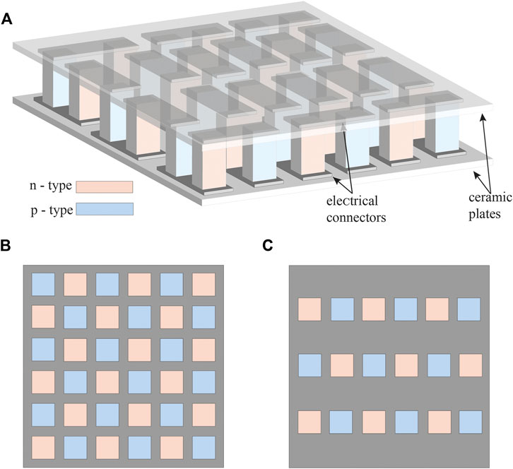
FIGURE 1. (A) Schematic of a thermoelectric module with multiple n- and p-type leg couples. (B) Top view of the module. (C) Representation showing a fill factor that is 50% of the one in (B).
In traditional thermoelectric devices, legs are rectangular, and modules are rigid squares (as shown in Figure 1). Re-envisioning the thermoelectric module structure and manufacturing approach enables new, non-rectangular designs and methods for system optimization. Some system designs minimize parasitic thermal resistances by conforming the thermoelectric device to the waste-heat source’s hot surface. Since many hot surfaces in potential waste-heat recovery applications are curved pipes, curved or circular thermoelectric legs have been developed to enable more effective heat recovery. For example Gentherm showed circular thermoelectric devices for vehicle exhaust heat recovery (Jovovic, 2014). Schmitz et al. (2013) sintered ring-shaped thermoelectric legs for tubular thermoelectric modules, and a patent on tubular thermoelectric modules is issued to Nishimoto and Kitayama (1997). Radial thermoelectric architectures with varied leg lengths and fill factors were explored by Menon et al.; their design aimed to capture heat from a hot fluid in a pipe and allow natural convection on the outside of the thermoelectric to provide cold side cooling (Menon and Yee, 2016; Menon et al., 2017).
Still other designs alter the shape of the individual thermoelectric legs. Crane and Bell (2006) demonstrated how a Y-shaped leg enabled better thermal management. Sahin et al. investigated trapezoidal thermoelectric leg configurations and showed that changing the cross-sectional area along the leg length can improve device efficiency (Al-Merbati et al., 2013; Sahin and Yilbas, 2013; Ali et al., 2014). Similarly, Fabián-Mijangos et al. (2017) demonstrated both numerically and experimentally that asymmetrical (pyramidal) thermoelectric legs lower the overall thermal conductance of the device and increase the temperature difference along the legs. Their experiment showed that the thermoelectric figure-of-merit nearly doubled compared to a conventional thermoelectric module. They also showed that a module consisting of asymmetrical legs achieve 66% greater power output compared to a module consisting of symmetrical legs (Fabián-Mijangos et al., 2017). Thimont and LeBlanc (2019) showed the impacts of changing the cross-sectional area at multiple points along the leg length and making the interior leg hollow; they investigate legs made of bismuth telluride and higher manganese silicide under a constant hot side temperature boundary condition with radiative heat flux on the cold side. A module with layered leg geometry obtained 46% higher electrical potential and 48% higher power output compared to the module with rectangular thermoelectric legs Thimont and LeBlanc (2019). Ibeagwu (2019) studied various leg shapes including trapezoidal, X, I, Y shapes under a constant temperature boundary condition and found that the X-shaped leg generated the highest power density; the X-shaped leg resulted in a 19% power density improvement over the conventional rectangular leg shape.
The work presented in this study builds on these prior studies to numerically investigate how a variety of leg shapes would impact the thermal and electrical resistances (and thus power generation potential) of legs under multiple realistic operating conditions. Unlike previous studies that investigated only one or two different leg shapes, this work investigates nine leg shapes, enabling a much more holistic understanding of what geometric features impact thermoelectric performance. Both constant temperature and heat flux boundary conditions are modeled on both the hot and cold sides as opposed to prior studies which only modeled constant temperature conditions. Our range of boundary conditions captures the varied, realistic application scenarios in which thermoelectric modules might be used for waste-heat recovery. Simulations were performed for two materials, bismuth telluride and silicon germanium, to capture two very different low and high temperature operation scenarios.
Methods
Leg Shapes
The goal of this work is to investigate the impact of leg geometry on the temperature and electrical potential gradients across the leg, so nine different leg shapes were selected as shown in Figure 2. The baseline is a rectangular prism (Figure 2A) because this shape is the standard leg geometry found in commercial thermoelectric modules. According to a market survey done on thermoelectric legs dimensions, the thicknesses of commercial thermoelectric devices are 1.5–8 mm. This reported height includes the ceramic plates and electrical connectors because device specifications do not state only the thermoelectric leg length (Sisik, 2020). The trapezoidal shapes (Figures 2B,C) are simple shapes that allow us to explore the impact of changing the leg cross-sectional area along the leg length (i.e., along the direction of the temperature gradient and perpendicular to the direction of heat transfer). These shapes were explored in prior work (Sahin and Yilbas, 2013; Ibrahim et al., 2014; Shittu et al., 2019) and thus provide a starting point for exploring the impact of leg geometry. The hourglass and inverse hourglass shapes (Figures 2D,E) have the same volume and the same nominal thermal and electrical resistances. However, the section of the leg with the largest cross-sectional area is in a different location with respect to the boundaries. For the hourglass shape, the largest cross-sectional areas are in contact with the hot and cold side thermal boundaries. For the inverse hourglass shape, the smallest cross-sectional areas contact the thermal boundaries. The Y-shape and reverse Y-shape (Figures 2F,G) incorporate a simple split in the leg, making the length for carrier transport longer even though the overall height of the leg is the same as that for the other shapes. In the hollow rectangular shape (Figure 2H), the cross-sectional area is smaller for most of the leg length, thus increasing the thermal resistance, but the cross-sectional area in contact with the hot and cold side boundaries is the full cross-sectional area of the leg (i.e., the maximum possible cross-sectional area). The multi-hollow rectangular shape (Figure 2I) provides another representation of reducing the cross-sectional area within the same 4 mm × 4 mm footprint of each leg shape. The split and hollow regions in the latter three leg shapes result in radiative heat transfer between interior surfaces of the leg.
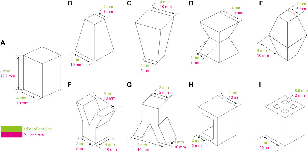
FIGURE 2. Thermoelectric leg shapes investigated in this study were: (A) rectangular (the conventional leg shape), (B) trapezoid, (C) reverse trapezoid, (D) hourglass, (E) inverse hourglass, (F) Y, (G) reverse Y, (H) hollow rectangular, and (I) multi-hollow rectangular.
The dimensions chosen for the legs are based on typical thermoelectric modules. For bismuth telluride legs, the leg is restricted to fit within a 4 mm × 4 mm ×6 mm volume. Since silicon germanium is used at higher temperatures, the legs are typically larger, so the silicon germanium leg is restricted to fit within 10 mm × 10 mm × 12.7 mm. Since all of the leg shapes have the same length, the relative performance of each shape (how the performance of a given shape compares to that of the other legs) should be the same regardless of the leg length, so the conceptual findings are extensible to other leg lengths. The choice to confine all shapes to the same volume stipulates that the fill factor is the same regardless of the leg shape. Therefore, each shape would fill the same fraction of projected area in a thermoelectric module. Even if some shapes do not have thermoelectric material filling the projected area (e.g., the Y, hollow rectangular, multi-hollow rectangular shapes in Figures 2F–I), the projected area required for the leg would still be 4 mm × 4 mm (bismuth telluride legs) or 10 mm × 10 mm (silicon germanium legs). As described in the previous section and demonstrated in (Glatz et al., 2009), the fill factor provides a degree of freedom in designing the thermoelectric module to impact device performance. We constrain that degree of freedom in order to explore only the impact of the leg shape and prevent changes in leg shape from also implying a change in fill factor.
Boundary Conditions
We explore the impact of thermal boundary condition on the temperature gradient (and thus electrical potential) across the thermoelectric leg because potential waste-heat recovery applications could alternately impose constant temperature or constant heat flux boundary conditions. Although many thermoelectric device simulations apply constant temperature boundary conditions, constant heat flux boundary are more representative of certain applications and result in different device performance (Hendricks, 2014; Fabián-Mijangos et al., 2017; Tan et al., 2020). For example, waste-heat recovery from an exhaust stream is best modeled with a heat flux boundary condition. The exhaust stream temperature changes as it flows across the thermoelectric device surface, and heat transfer occurs from the exhaust fluid to the thermoelectric device surface. On the other hand, a thermoelectric device attached to a glass kiln or metal processing furnace is best modeled with a constant temperature boundary condition because the furnace remains at the constant temperature dictated by the material processing requirements. The cold side boundary conditions also depend on system operation. The cold side of the thermoelectric device could be passively cooled (e.g., natural convection in air) or actively cooled (e.g., forced convection with a cooling fluid). In some circumstances, the cold side temperature can be treated as a constant temperature either because of aggressive cooling (e.g., forced cooling with an extremely large convection coefficient such that the cold side temperature is essentially the temperature of the cooling fluid) or an application where the device is attached to a cold reservoir.
In this work, we show the impact of both constant temperature and constant heat flux boundary conditions. The specific hot and cold side boundary condition values are shown in Figure 3; they vary based on the material modeled to reflect each material’s suitability for low and high temperature applications (as discussed in the following section). The specific hot side values shown in Figure 3 were selected based on the temperature range in which each thermoelectric material’s figure of merit is highest; the cold side values were selected based on typical cooling approaches as discussed above.
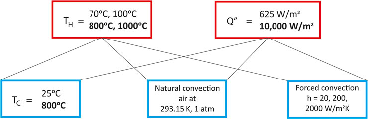
FIGURE 3. Hot and cold side boundary condition scenarios modeled for all of the leg shapes. Each hot side condition (constant temperature or constant heat flux, in red boxes) was modeled with each cold side condition (constant temperature, natural convection, and three forced convection coefficients h, in blue boxes). When different values were used based on the thermoelectric material, the designation is indicated with regular font for bismuth telluride and bold font for silicon germanium. The boundary condition combinations applied to the nine leg shapes shown in Figure 2 resulted in 270 simulations, 135 for bismuth telluride and 135 for silicon germanium.
The exterior side surfaces of the legs are treated as adiabatic surfaces. This condition approximates a device in which the spaces between the thermoelectric legs are filled with a thermally insulating material, thus driving the heat through the thermoelectric leg. If the thermoelectric device were filled with a gas or evacuated, radiative heat transfer from the exterior surfaces would occur. For the legs with interior surfaces (i.e., the Y, hollow rectangular, and multi-hollow rectangular shapes), radiative heat transfer between the interior surfaces was applied.
Materials
Thermoelectric properties S, σ, and k vary with temperature, and the ZT of various thermoelectric materials peak at different temperatures. Therefore, the selection of thermoelectric material for a given application depends on the temperature range the material will experience in the application and whether its ZT is optimized for that temperature range. Numerous thermoelectric materials exist and have been compared in notable reviews (Sootsman et al., 2009; Tritt, 2011; Liu et al., 2012). However, only a few thermoelectric materials have been demonstrated in applications beyond lab-scale prototypes. Two thermoelectric materials, bismuth telluride and silicon germanium, were selected to capture low and high temperature applications. These two materials have long histories of operation in commercial and non-commercial thermoelectric devices. Bismuth telluride was selected for low temperature scenarios because it is the typical low temperature thermoelectric material and has the highest ZT at low temperatures (below 150°C). It is the material found in the overwhelming majority of commercial thermoelectric devices, and it is the low temperature standard reference material (Lowhorn et al., 2011). The temperature-dependent properties for (Bi0.5Sb0.5)2Te3 were used in the model; these correspond to the material properties in the COMSOL materials library and are shown below in Figure 4 (Jaegle, 2008).
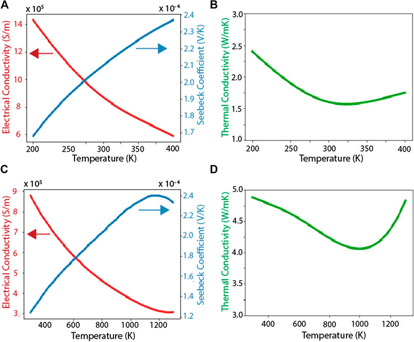
FIGURE 4. Material properties of thermoelectric materials used in the simulations. (A) Electrical conductivity, Seebeck coefficient, and (B) thermal conductivity (Bi0.5Sb0.5)2Te3. (C) Electrical conductivity, Seebeck coefficient, and (D) thermal conductivity of Si0.78Ge0.22.
Silicon germanium was selected for high temperature scenarios. Silicon germanium was one of the earliest high temperature thermoelectric materials, used primarily for power generation on space vehicles (Radio, 1963; Furlong and Wahlquist, 1999). The properties used in this study are taken from (Rowe, 1995); these are the properties for silicon germanium used in the radioisotope thermoelectric generators developed by the NASA Jet Propulsion Laboratory. These properties are not the silicon germanium material properties listed in the COMSOL materials library because the COMSOL library uses properties measured on silicon germanium thin films (Jellison et al., 1993). The properties reported in (Rowe, 1995) are more representative of bulk silicon germanium that would be used in a thermoelectric device for waste-heat recovery.
Numerical Modeling
The numerical modeling of different thermoelectric leg shapes was conducted with the COMSOL Multiphysics® software which enables finite element analysis and multiphysics solutions. The investigation used the heat transfer module with the thermoelectric effect within COMSOL. Legs were modeled in three dimensions. Single operation meshing was used with the global size node set to the predefined normal value. Free tetrahedral nodes were used for meshing with 15–20 free tetrahedra along the leg’s z-axis. Minimum and maximum element sizes were 0.108 and 0.6 mm for the bismuth telluride legs and 0.229 and 1.27 mm for the silicon germanium legs.
We validated our numerical approach in part by first duplicating another numerical solution for thermoelectric device modeling (Jaegle, 2008). In Jaegle’s work, a COMSOL Multiphysics simulation was carried out for thermoelectric generation. We tested our COMSOL model with the leg dimensions and boundary conditions used by Jaegle to verify our model produced the same results. We also validated our solution with an analytical solution that solves energy balance equations applied to vertical partitions of the thermoelectric leg (Sisik, 2020).
The open circuit potential Voc was determined by defining an electrical ground at the top surface and evaluating the electrical potential across the leg. The short circuit current Isc was determined by applying an equal voltage condition (0 V) to the terminal (bottom surface) to create a short circuit condition. The electrical resistance Re of the leg was found using the open circuit voltage Voc divided by the short circuit current Isc, and the power output was determined by
where the current I can vary based on the load resistance. The maximum power output Pmax was calculated by
These approaches were applied to analyze the projected behavior (thermal and electrical resistance, electrical potential, and power generation) of all nine leg shapes (Figure 2) under the ten boundary condition scenarios (Figure 3). Thus, two hundred seventy simulations were performed, and their results provide the thermal resistance and electrical potential for bismuth telluride and silicon germanium thermoelectric legs under combinations of constant temperature and heat flux boundary conditions.
Results and Discussion
The scenarios modeled here reveal the condition under which variations in the thermoelectric leg shape have the most impact. Quantitative results for all of the scenarios simulated (totaling two hundred seventy scenarios) are presented in the Supplementary Information . A summary and analysis of the key findings are discussed here.
Constant Temperature Hot Side Boundary Condition
Perhaps the most passive conditions a thermoelectric device experiences occur when the device is attached to a hot surface without active cooling on the device cold side (i.e., boundary conditions of a constant hot side temperature and natural convection on the cold side). The results for bismuth telluride legs under these conditions are shown in Figure 5 where the temperature difference across the leg, the leg electrical resistance, the electrical potential associated with the temperature difference, and the maximum potential power output are shown relative to those of a traditional rectangular leg for bismuth telluride and silicon germanium legs. Figure 6 shows how the power generation potential varies as a function of current (or load resistance) for the various leg shapes with a low cold side convection coefficient of 20 W/m2-K.
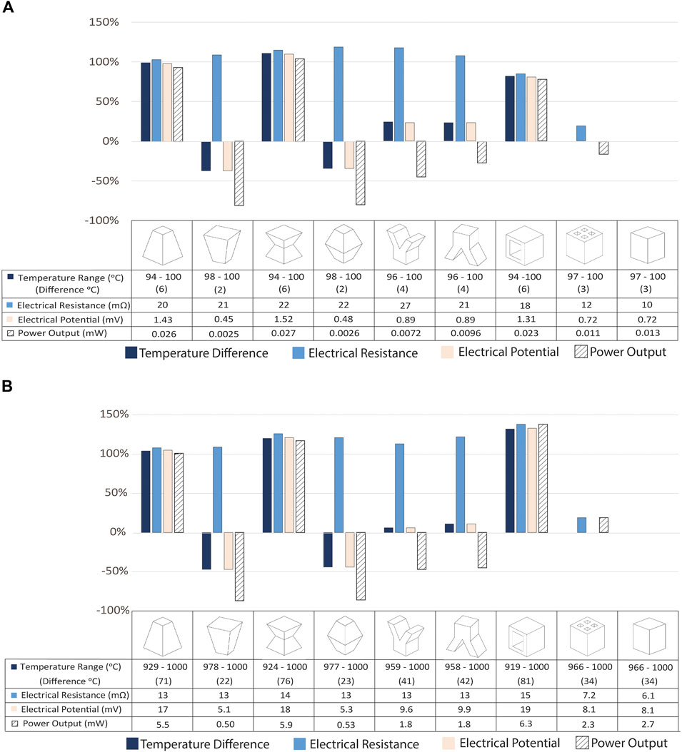
FIGURE 5. The percent change in the temperature range across each leg, the leg electrical resistance and potential, and maximum power generation potential compared to those for a rectangular (conventional) shaped leg are shown for constant hot side temperature (Th) and cold side natural convection boundary conditions for (A) (Bi0.5Sb0.5)2Te3 (Th = 100 C) and (B) Si0.78Ge0.22 (Th = 1,000 C) legs of varying shapes. The tables below the plots show the computed values of the performance metrics.

FIGURE 6. Power generation potential as a function of current (load resistance) for various leg shapes are shown for constant hot side temperature (Th) and cold side forced convection (convection coefficient h = 20 W/m2-K) boundary conditions for (A) (Bi0.5Sb0.5)2Te3 (Th = 100 C) and (B) Si0.78Ge0.22 (Th = 1,000 C) legs of varying shapes.
In terms of power generation potential, the most advantageous leg shapes are the trapezoid, hourglass, and rectangular hollow shapes; with 93, 104, 78% (for bismuth telluride) and 104, 120, 132% (for silicon germanium) higher power output than the conventional rectangular shape, respectively. The hourglass shape would result in the highest power generated. The trapezoid and hourglass shapes perform better than the conventional rectangular shape because they have higher thermal resistances. In this case, the temperature difference across the leg is a proxy for the thermal resistance. A 1D thermal resistance in the form L/kA (where L, A, and k are leg length, cross-sectional area, and thermal conductivity, respectively) is not straightforward when the cross-sectional area varies along the leg length in different ways for each leg shape. Higher thermal resistance results in larger temperature gradients across the legs. The trapezoid and hourglass shapes result in larger thermal resistances because their largest cross-sectional areas are at the cold side, enabling greater heat transfer rate from the leg compared to the reverse trapezoid, inverse hourglass, Y, and multi-hollow shapes. Other studies that investigated the trapezoid, hourglass and hollow shapes found similar improvement in terms of power generation when compared to the traditional rectangular shape. Thimont and LeBlanc (2019) found that a trapezoid shape and hollow shapes perform better than the traditional rectangular shape under constant hot side temperature boundary condition. Ibeagwu found an hourglass shape (referred to as X-shape in that study) subjected to hot and cold junction temperatures of 420 and 300 K has 19% higher power output compared to the conventional rectangular leg shape (Ibeagwu, 2019).
The rectangular hollow shape performs better than the traditional rectangular shape whereas the multi-hollow rectangular shape has the same performance as the rectangular shape under these boundary conditions. The rectangular hollow shape has the same length but smaller cross-sectional area along the leg length which results in a greater thermal resistance. As the thermal resistance increases, the electrical potential across the leg increases, resulting in a larger power output. The multi-hollow rectangular shape also has a lower cross-sectional area along the leg length than the rectangular shape, but the area at the bottom is different. The multi-hollow shape has less surface area from which heat transfer occurs at the bottom (cold side) of the leg, and the amount of heat transferred out of the leg at the bottom side is proportional to this area. Thus, the heat rejected is lower for the multi-hollow rectangular shape, outweighing the benefit of having a smaller cross-sectional area along the leg length.
Under the hot side constant temperature boundary condition, the advantage of changing leg shape diminishes as the cold side convection coefficient increases. Figure 7 demonstrates this effect for the hourglass leg shape. The cold side constant temperature boundary condition is the limiting scenario as it is equivalent to an extremely high convection coefficient. Under such conditions (i.e., constant temperature boundary conditions on the hot and cold sides), there is no advantage to changing the leg shape relative to the traditional rectangular prism shape. With cold side convection boundary conditions, the relative thermal resistances (leg thermal resistance and convection thermal resistance) dictate the leg’s cold side temperature. Thus, the impact of the leg shape on the thermal resistance of the leg enables higher power output potential when the leg thermal resistance increases – even though that leg shape results in higher electrical resistance. However, with a fixed cold side temperature, the impact of leg shape on leg thermal resistance is eliminated because the temperature gradient is fixed rather than determined by the leg thermal resistance. So, the only differentiating metric becomes the electrical resistance which is higher for all of the non-traditional leg shapes.
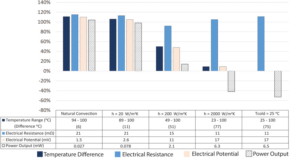
FIGURE 7. The change in performance for the hourglass leg shape for various cold side boundary conditions (natural convection, forced convection coefficients h = 20, 200, and 2,000 W/m2-K, and constant cold side temperatures Tc = 25, 300 C) and constant hot side temperature (Th). The percent change in the temperature range across the hourglass leg, leg electrical resistance and potential, and maximum power generation potential compared to those for a rectangular (conventional) shaped leg are shown for (Bi0.5Sb0.5)2Te3 (Th = 100 C). The trends for Si0.78Ge0.22 (Th = 1,000 C) are the same. The table below the plot shows the computed values of the performance metrics.
By comparison, the study conducted by Ibeagwu considered constant temperature boundary conditions for the hourglass shape (referred to as X-shape in that study) has a higher power density than the rectangular shape (Ibeagwu, 2019). Our study shows that other geometries [e.g., trapezoid, Y shape investigated in both our study and (Ibeagwu, 2019)] could result in a greater power output and hence power density if natural convection or forced convection boundary conditions are considered. In fact, convection boundary conditions on the cold side are more typical of the conditions experienced by thermoelectric devices in realistic waste-heat recovery applications. By simulating multiple boundary conditions (natural convection, forced convection and constant temperature boundary conditions), we were able to analyze comprehensive convection cooling options on the cold side and hence explore the actual potential of each leg shape investigated.
In many applications, increasing the cold side convection coefficient (or reducing the cold side thermal resistance) comes at a cost: it requires forced cooling with a liquid coolant. System complexity may increase as the cooling infrastructure is incorporated into the system design, typically entailing higher capital cost. Power may be required to pump the cooling fluid, so the net power (thermoelectric power generated minus the pumping power) decreases. Unless there is a readily available cold reservoir, the traditional rectangular leg shape is not optimal.
Constant Heat Flux Hot Side Condition
Since constant temperature boundary conditions are much harder to realize in practical applications, it is useful to consider a hot side constant heat flux boundary condition. Figure 8 shows the results for such a condition with a cold side natural convection boundary condition. The cross-sectional area of the leg at the hot side is pertinent under this condition because the heat transfer rate into the leg is the product of the heat flux and this area. Therefore, leg shapes with a smaller cross-sectional area at the hot side result in less heat input into the leg. As a result, the most advantageous leg shapes under these conditions are the reverse trapezoid, hourglass, and rectangular hollow with 53, 120, 88% (for bismuth telluride) and 71, 125, 138% (for silicon germanium) higher power output than the conventional rectangular shape, respectively. The hourglass shape results in the highest power generation potential for the same reasons described above under the hot side constant temperature boundary condition.
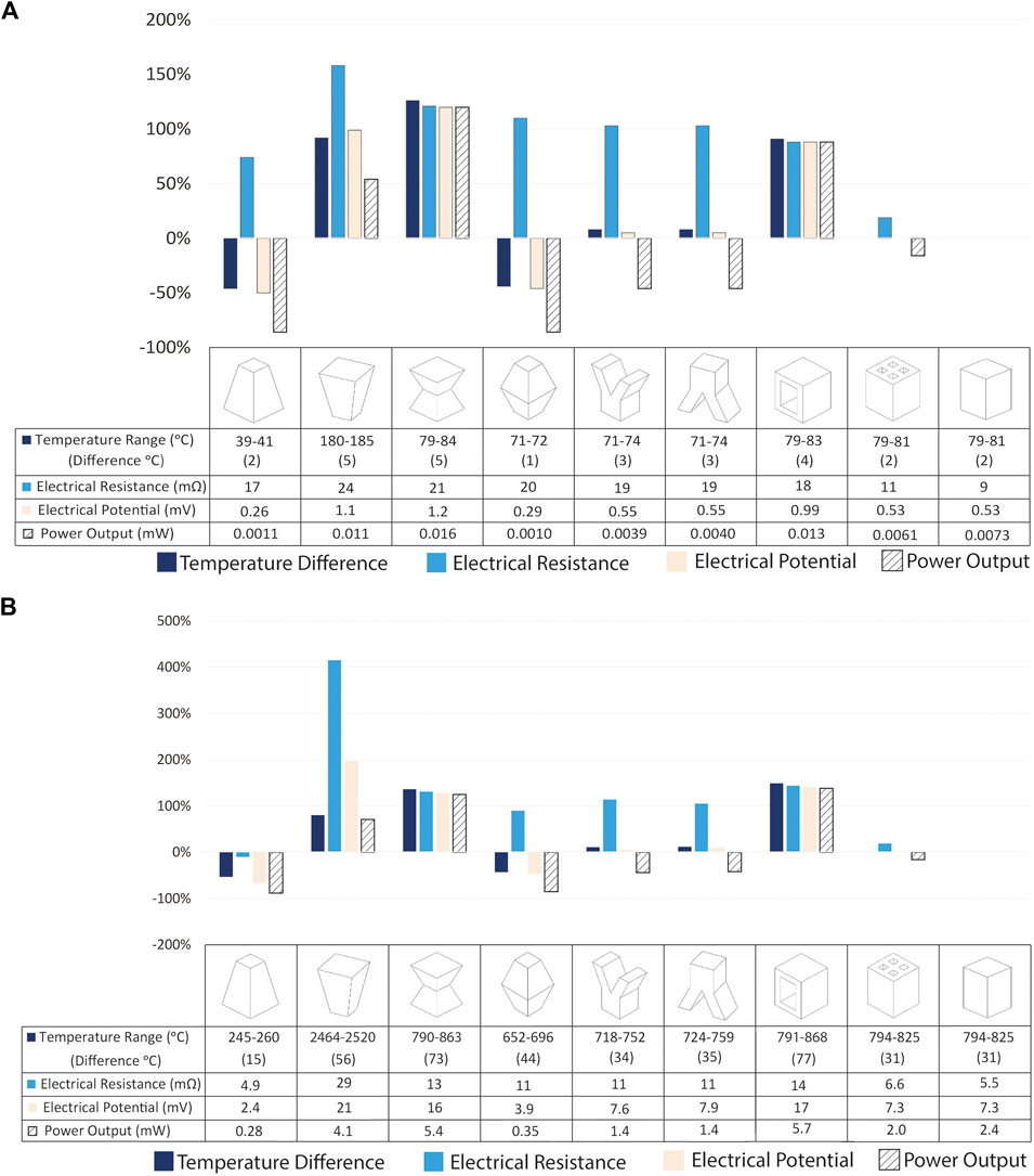
FIGURE 8. The percent change in the temperature range across each leg, leg electrical resistance and potential, and maximum power generation potential compared to those for a rectangular (conventional) shaped leg are shown for constant hot side heat flux (Qh”) and cold side natural convection boundary condition for (A) (Bi0.5Sb0.5)2Te3 (Qh” = 625 W/m2) and (B) Si0.78Ge0.22 (Qh” = 10,000 W/m2) legs of varying shapes. The tables below the plots show the computed values of the performance metrics.
Under a hot side constant heat flux boundary condition more heat energy is added to the leg shapes that have larger cross-sectional areas at the hot side. When the heat flux from the cold side is driven by natural convection, the temperature difference between the cold side surface (the bottom of the leg here) and the ambient air as well as the cold side cross-sectional area determine the heat output from the leg. The reverse trapezoid shape’s largest and smallest cross-sectional areas face the hot and cold sides, respectively, so this shape results in the largest temperature gradient across the leg. The hourglass and the rectangular hollow shapes have their biggest cross-sectional areas at the hot and cold sides. Similarly, these shapes enable greater heat input and output to the leg. Their thermal resistance is greater than the conventional rectangular shape, resulting in larger temperature differences and hence better electrical performance.
A key difference is the evolution of the impact of leg shape as the cold side boundary condition changes when the hot side has a heat flux boundary condition as shown in Figure 9. In this case, the cold side boundary condition does not override the impact of the leg shape on thermal resistance; the hot side temperature adjusts as a result of the leg thermal resistance. Similarly, the advantage of the reverse trapezoid, hourglass, and rectangular hollow leg shapes persists for all the cold side boundary conditions, even for the fixed cold side temperature boundary condition (see Supplemental Information). These results are particularly compelling because many potential waste-heat recovery applications (such as conversion of automobile exhaust heat into onboard electricity) would consist of a hot side heat flux boundary condition.
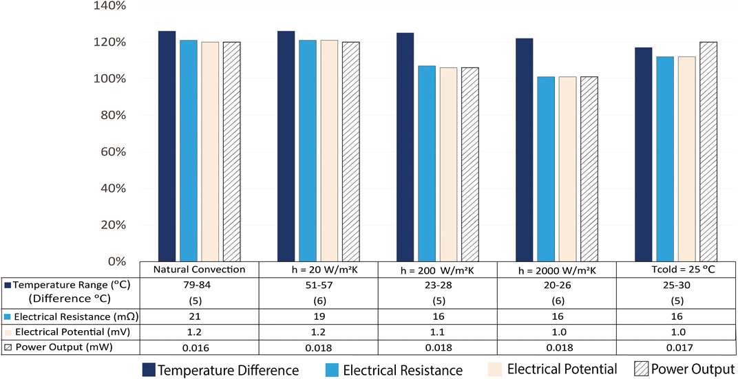
FIGURE 9. The change in performance for the hourglass leg shape for various cold side boundary conditions (natural convection, forced convection coefficients h = 20, 200, and 2,000 W/m2-K, and constant cold side temperature Tc = 25, 800 C) and constant hot side heat flux (Qh”). The percent change in the temperature range across the hourglass leg, leg electrical resistance and potential, and maximum power generation potential compared to those for a rectangular (conventional) shaped leg are shown for (Bi0.5Sb0.5)2Te3 (Qh” = 625 W/m2). The trends for Si0.78Ge0.22 (Qh” = 10,000 W/m2) are the same. The table below the plot shows the computed values of the performance metrics.
Conclusion
This work demonstrated the effect of different thermoelectric leg shapes on thermoelectric device performance. The way the cross-sectional area changes along the length of the leg as well as what cross-sectional area is in contact with the hot and cold side boundaries are key factors in determining which leg shape will result in the highest thermal resistance and, ultimately, power output in a waste-heat recovery application. The results presented here show the conventional, rectangular leg shape found in commercial thermoelectric devices is not the optimal shape for heat-to-power energy conversion in typical application conditions.
The hourglass-shaped thermoelectric leg, subjected to a fixed temperature boundary condition, has the best thermal and electrical performance. The hourglass leg shape results in more than double the electrical potential and maximum power compared to the conventional rectangular shape with a cold side natural convection boundary condition. Under a hot side fixed heat flux boundary condition, the trapezoid leg shape (with the largest cross-sectional area at the hot side) results in almost double the electrical potential and a 50% increase in the power output compared to the conventional leg shape. While a trapezoid leg shape enables an almost 100% increase in electrical potential and power output under constant temperature boundary condition, the same shape results in an approximately 50% decrease in electrical potential and power output under constant heat flux boundary condition. These findings show the coupling of the boundary conditions with the leg shape is critical to the thermoelectric module performance.
As new methods for manufacturing thermoelectric legs advance, novel geometries become increasingly accessible. The results for the simple leg shapes investigated here provide sufficient basis for designing more complex leg shapes that take advantage of the understanding provided about changing cross-sectional area, incorporating hollow features, and linking leg area to the thermal boundary conditions. Therefore, this work provides insights that inform advanced thermoelectric leg design and optimization.
Data Availability Statement
The original contributions presented in the study are included in the article/Supplementary Material, further inquiries can be directed to the corresponding author/s.
Author Contributions
BS conducted the numerical modeling. BS and SL analyzed results and wrote the manuscript.
Funding
These findings are based upon work supported by the National Science Foundation under Grant No. CMMI-1943104 and the Office of Naval Research under Award No. N00014-20-1-2365.
Conflict of Interest
The authors declare that the research was conducted in the absence of any commercial or financial relationships that could be construed as a potential conflict of interest.
Acknowledgments
The authors gratefully acknowledge support from these sources.
Supplementary Material
The Supplementary Material for this article can be found online at: https://www.frontiersin.org/articles/10.3389/fmats.2020.595955/full#supplementary-material
References
Ali, H., Sahin, A. Z., and Yilbas, B. S. (2014). Thermodynamic analysis of a thermoelectric power generator in relation to geometric configuration device pins. Energy Convers. Manag. 78, 634–640. doi:10.1016/j.enconman.2013.11.029
Al-Merbati, A. S., Yilbas, B. S., and Sahin, A. Z. (2013). Thermodynamics and thermal stress analysis of thermoelectric power generator: influence of pin geometry on device performance. Appl. Therm. Eng. 50, 683–692. doi:10.1016/j.applthermaleng.2012.07.021
Caillat, T., Fleurial, J. P., Snyder, G. J., and Borshchevsky, A. (2001). “Development of high efficiency segmented thermoelectric unicouples,” in The 20th international conference on thermoelectrics, Pasadena, CA, February 2001. doi:10.1109/ict.2001.979888
Crane, D. T., and Bell, L. E. (2006). “Progress towards maximizing the performance of a thermoelectric power generator,” in The 25th international conference on thermoelectrics, Vienna, Austria, September 2006. doi:10.1109/ICT.2006.331259
Dunham, M. T., Barako, M. T., LeBlanc, S., Asheghi-Roudheni, M., Chen, B., and Goodson, K. (2013). “Modeling and optimization of small thermoelectric generators for low-power electronics,” in ASME international technical conference and exhibition on packaging and integration of electronic and photonic microsystems, Burlingame, CA, July 16–18, 2013. doi:10.1115/IPACK2013-73297
Ebling, D., Bartholomé, K., Bartel, M., and Jägle, M. (2010). Module geometry and contact resistance of thermoelectric generators analyzed by multiphysics simulation. J. Electron. Mater. 39, 1376. doi:10.1007/s11664-010-1331-0
Fabián-Mijangos, A., Min, G., and Alvarez-Quintana, J. (2017). Enhanced performance thermoelectric module having asymmetrical legs. Energy Convers. Manag. 148, 1372–1381. doi:10.1016/j.enconman.2017.06.087
Freunek, M., Müller, M., Ungan, T., Walker, W., and Reindl, L. M. (2009). New physical model for thermoelectric generators. J. Electron. Mater. 38, 1214–1220. doi:10.1007/s11664-009-0665-y
Furlong, R. R., and Wahlquist, E. J., (1999). U.S. space missions using radioisotope power systems. Nuclear News, 26–34
Glatz, W., Schwyter, E., Durrer, L., and Hierold, C. (2009). Based flexible micro thermoelectric generator with optimized design. J. Microelectromech. Syst. 18, 763. doi:10.1109/JMEMS.2009.2021104
Gomez, M., Reid, R., Ohara, B., and Lee, H. (2013). Influence of electrical current variance and thermal resistances on optimum working conditions and geometry for thermoelectric energy harvesting. J. Appl. Phys. 113, 174908. doi:10.1063/1.4802668
Hendricks, T., and Choate, W. T. (2006). Engineering scoping study of thermoelectric generator systems for industrial waste heat recovery. Office of Scientific and Technical Information. doi:10.2172/1218711
Hendricks, T. J. (2014). “Integrated thermoelectric-thermal system resistance optimization to maximize power output in thermoelectric energy recovery systems,” in Materials research society symposium proceedings, Boston, December 1–6, 2013. 1642. doi:10.1557/opl.2014.734
Hodes, M. (2007). Optimal pellet geometries for thermoelectric refrigeration. IEEE Trans. Compon. Packag. Technol. 30, 50–58. doi:10.1109/TCAPT.2007.892068
Ibeagwu, O. I. (2019). Modelling and comprehensive analysis of TEGs with diverse variable leg geometry. Energy 180, 90–106. doi:10.1016/j.energy.2019.05.088
Ibrahim, A., Rahnamayan, S., Vargas Martin, M., and Yilbas, B. (2014). Multi-objective thermal analysis of a thermoelectric device: influence of geometric features on device characteristics. Energy 77, 305–317. doi:10.1016/j.energy.2014.08.041
Jaegle, M. (2008). “Multiphysics simulation of thermoelectric systems - modeling of PeltierCooling and thermoelectric generation,” in COMSOL Conference, Hannover, Germany.
Jellison, G. E., Haynes, T. E., and Burke, H. H. (1993). Optical functions of silicon-germanium alloys determined using spectroscopic ellipsometry. Opt. Mater. 2, 105–117. doi:10.1016/0925-3467(93)90035-y
Johnson, I., Choate, W. T., and Amber, D. (2008). Waste heat recovery. Technology and opportunities in U.S. Industry. Washington, DC: BCS Inc. doi:10.2172/1218716
Jovovic, V. (2014). Thermoelectric waste heat recovery program for passenger vehicles. Available at: http://energy.gov/sites/prod/files/2014/07/f17/ace080_barnhart_2014_o.pdf (Accessed June 10, 2020).
LeBlanc, S. (2014). Thermoelectric generators: linking material properties and systems engineering for waste heat recovery applications. Sustain. Mater. Tech. 1–2, 26–35. doi:10.1016/j.susmat.2014.11.002
LeBlanc, S., Shannon, K. Y., Scullin, M. L., Dames, C., and Goodson, K. E. (2013). Material and manufacturing cost considerations for thermoelectrics. Renew. Sustain. Energy Rev. 32, 313–327. doi:10.1016/j.rser.2013.12.030
Liu, W., Yan, X., Chen, G., and Ren, Z. (2012). Recent advances in thermoelectric nanocomposites. Nano Energy. 1, 42–56. doi:10.1016/j.nanoen.2011.10.001
Lowhorn, N. D., Wong-Ng, W., Lu, Z.-Q., Martin, J., Green, M. L., Bonevich, J. E., et al. (2011). Development of a Seebeck coefficient standard reference material. J. Mater. Res. 26, 1983–1992. doi:10.1557/jmr.2011.118
Menon, A. K., Meek, O., Eng, A. J., and Yee, S. K. (2017). Radial thermoelectric generator fabricated from n- and p-type conducting polymers. J. Appl. Polym. Sci. 134, 44060. doi:10.1002/app.44060
Menon, A. K., and Yee, S. K. (2016). Design of a polymer thermoelectric generator using radial architecture. J. Appl. Phys. 119, 055501. doi:10.1063/1.4941101
Nishimoto, Y. F. S., and Kitayama, T. (1997). Tubular thermoelectric module. 526U.S. patent 6,096,966A
Radio Corporation of America (1963). Optimization of silicon-germanium thermoelectric modules for transportation corps silent boat design. Defense documentation center for scientific and technical information,. (Accessed July 1, 2020).
Sahin, A. Z., and Yilbas, B. S. (2013). The thermoelement as thermoelectric power generator: effect of leg geometry on the efficiency and power generation. Energy Convers. Manag. 65, 26. doi:10.1016/j.enconman.2012.07.020
Schmitz, A., Stiewe, C., and Müller, E. (2013). Preparation of ring-shaped thermoelectric legs from PbTe powders for tubular thermoelectric modules. J. Electron. Mater. 42, 1702. doi:10.1007/s11664-012-2402-1
Shittu, S., Li, G., Zhao, X., and Ma, X. (2019). Series of detail comparison and optimization of thermoelectric element geometry considering the PV effect. Renew. Energy. 130, 930–942. doi:10.1016/j.renene.2018.07.002
Sisik, B. (2020). Numerical modeling of leg geometries in thermoelectric devices. Washington, DC: The George Washington University.
Snyder, G. J., and Toberer, E. S. (2008). Complex thermoelectric materials. Nat. Mater. 7, 105. doi:10.1038/nmat2090
Sootsman, J. R., Chung, D. Y., and Kanatzidis, M. G. (2009). New and old concepts in thermoelectric materials. Angew. Chem. Int. Ed. 48, 8616–8639. doi:10.1002/anie.200900598
Tan, Q., Chen, G., Sun, Y., Duan, B., Li, G., and Zai, P. (2020). Performance of annular thermoelectric couples by simultaneously considering interface layers and boundary conditions. Appl. Therm. Eng. 174, 115301. doi:10.1016/j.applthermaleng.2020.115301
Thimont, Y., and LeBlanc, S. (2019). The impact of thermoelectric leg geometries on thermal resistance and power output. J. Appl. Phys. 126, 095101. doi:10.1063/1.5115044
Tritt, T. M. (2011). Thermoelectric phenomena, materials, and applications. Annu. Rev. Mater. Res. 41, 433–448. doi:10.1146/annurev-matsci-062910-100453
Keywords: thermoelectric performance, thermoelectric power, thermoelectric geometry, thermoelectric leg, thermoelectric manufacturing
Citation: Şişik B and LeBlanc S (2020) The Influence of Leg Shape on Thermoelectric Performance Under Constant Temperature and Heat Flux Boundary Conditions. Front. Mater. 7:595955. doi: 10.3389/fmats.2020.595955
Received: 18 August 2020; Accepted: 16 October 2020;
Published: 17 November 2020.
Edited by:
Emrah Celik, University of Miami, United StatesReviewed by:
Hock Jin Quah, University of Science, MalaysiaMutabe Aljaghtham, Prince Sattam Bin Abdulaziz University, Saudi Arabia
Copyright © 2020 Sisik and LeBlanc. This is an open-access article distributed under the terms of the Creative Commons Attribution License (CC BY). The use, distribution or reproduction in other forums is permitted, provided the original author(s) and the copyright owner(s) are credited and that the original publication in this journal is cited, in accordance with accepted academic practice. No use, distribution or reproduction is permitted which does not comply with these terms.
*Correspondence: Saniya LeBlanc, c2xlYmxhbmNAZ3d1LmVkdQ==